1
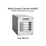
Orion NAS 820SR User Manual
42-30000-5115
Version 1.1
NAS Series—
Network Hard Disk Drive Array
Operation Manual
Foreword
Foreword
About this manual
The purpose of this manual is to assist users to understand the Orion
820 SR family of Network Attached Storage with Hard Disk Drive
Array functionality and to operate the system easily.
All information in this manual have been verified carefully to ensure
the correctness of its contents. In case of negligence or error, please
provide feedback to us. MaxTronic International Co., Ltd. reserves the
right to modify the contents of this manual without any notice in
advance.
Limited Warranty
MaxTronic International Co., Ltd. guarantees all network hard disk
drive arrays are thoroughly tested before they leave the factory and
should function normally under general conditions. In case of any
system malfunction, MaxTronic International Co., Ltd. and its local
representatives will be responsible for its repair without cost to the
customer, if the product failed within the warranty period and under
normal usage.
MaxTronic International Co., Ltd. is not responsible for any damage or
loss of data, deemed to be caused by its products. It is highly
recommended that Users conduct the necessary back-up practices.
EMC Certified
This product has passed FCC Class B inspection. Appropriate
certifications have also been approved, e.g. CE, UL, C-Tick, CB and
BSMI.
Copyright reserved. Do not duplicate. © 2007 MaxTronic International
Co., Ltd.
-1-
Foreword
Product Name: NAS system NAS Network Hard Disk Drive Array
Manual Revision: 1.1 (820SR)
Release Date: April, 2007
-2-
Content
Table of Contents
Thank You for purchasing Orion NAS System NAS
network hard disk drive array by MaxTronic
International Co., Ltd.!
To ensure proper installation and operation of the NAS network hard
disk drive array, please first read the operation guide and other
important information in this manual.
Foreword....................................................................1
About this manual........................................................................ 1
Limited Warranty.......................................................................... 1
EMC Certified .............................................................................. 1
Chapter 1 ............................................................... 1-1
Introduction to Orion 820SR NAS FAMILY ......... 1-1
1-1 Orion 820SR NAS Family Features....................................1-1
1-2 Using this Manual...............................................................1-2
1-3 Items in the Package ..........................................................1-5
Chapter 2 ............................................................... 2-1
Getting Started and Quick Configuration ........... 2-1
2-1 System Hardware Installation and Configuration ...............2-1
2-2 Hard Disk Drive Installation ................................................2-1
2-3 Network Connection ...........................................................2-3
2-4 System Bootup—Self Configuration Test ...........................2-4
2-5 IP Address ..........................................................................2-4
-i-
Content
2-6 Connecting to a Network ....................................................2-7
2-7 Administrator Login .............................................................2-7
2-8 System Information Screen ................................................2-8
2-9 Quick Configuration ............................................................2-9
2-11 Date, Time, and Region ..................................................2-11
2-12 Network Settings.............................................................2-12
2-13 Adding Storage Volume ..................................................2-13
2-14 Enabling Windows Network Service ...............................2-24
Chapter 3 ................................................................3-1
Using Administrative Tools For Administrator ...3-1
3-1 Login ...................................................................................3-1
3-2 Administrator Login .............................................................3-2
3-3 Quick Configuration ............................................................3-2
3-4 System Setups....................................................................3-3
3-5 Network Settings...............................................................3-16
3-6 Storage Volume Settings ..................................................3-45
3-7 User Privilege Settings .....................................................3-70
3-8 System Status...................................................................3-89
3-9 Backup Sync.....................................................................3-98
3-10 Diagnostic mode ...........................................................3-108
3-11 Logout ...........................................................................3-110
3-12 Shutdown...................................................................... 3-111
3-13 User-Level Access ........................................................3-112
3-14 Changing Password......................................................3-113
Chapter 4 ................................................................4-1
Using the LCD Control Panel ...............................4-1
4-1 Front Control Panel Functions Introduction ........................4-2
-ii-
Content
4-2 Basic Menu Options on the LCD Control Panel .................4-4
4-4 System Memory Size..........................................................4-6
4-5 CPU Information .................................................................4-6
4-6 Advanced Menu Options ....................................................4-6
4-7 Network Menu ....................................................................4-7
4-8 System Menu .....................................................................4-8
4-9 Miscellany Menu.................................................................4-8
Chapter 5 ............................................................... 5-1
System Operation ................................................. 5-1
5-1 Normal Operation ...............................................................5-1
5-2 Data Synchronization .........................................................5-2
5-3 Hard Disk Drive Damage....................................................5-2
5-4 Hard Disk Drive Replacement ............................................5-3
5-5 Automatic Data Recovery ...................................................5-4
Limited Warranty................................................... L-1
-iii-
Chapter 1
Chapter 1
Introduction to Orion 820SR NAS
FAMILY
Orion 820SR Family of NAS by MaxTronic International Co., Ltd. is a
RAID enabled NAS (Network Attached Storage). The ability of the unit
to conduct continual self tests, beyond unsymmetrical fault tolerance,
data validation functions provided by RAID Level 0, Level 1, Level 3
and Level 5, the availability of cooling fans and hot-swap function
make the Orion 820 family of network attached storage with hard disk
drive array even more stable and easy to use.
1-1 Orion 820SR NAS Family Features
z Completely OS Independent networking storage system.
z Basic system configuration is easily done via web browser.
z LCD Front Control Panel displays the system status and OS
Configuration.
z Hard Disk Drive Error indicator LED.
z Automatic Formatting, Data Replacement and Recovery.
z Optimized Data Access through the setting of stripe size of hard
disk drive.
z Support UPS devices (APC Smart UPS and Back UPS
ES500(RS-232)).
z Support 2xRJ45 Ethernet Port. (Two 10/100/1000 Mb)
z Quick Configuration Function makes first-time system
-1-1-
Chapter 1
configuration easy.
z Firmware upgradeable.
z Support hard disk drive hot-swap and Global hot-spare.
z Fan and Power System Failure automatic detection.
z Automatic over-temperature detection.
1-2 Using this Manual
The following icons will help you to identify important information,
when use this manual.
This icon indicates helpful key points and information.
This icon indicates a warning, to avoid making damages to
the software, the hardware, or the data.
Important Safety Instructions, Care and Handling
Before starting, take a few minutes to read this
manual. Read all of these instructions and save this
manual for later reference.
Protect the disk array system from extremely high or
low temperatures. Let the disk array system warm (or
cool) to room temperature before using it.
Protect the disk array system from being bumped or
dropped. Do not place the disk array system on an
unstable cart, stand, or table. It may fall, causing
serious damage to the product.
-1-2-
Chapter 1
Keep the disk array system away from magnetic
forces.
Do not use the disk array system near water.
Keep the disk array system away from dust, sand, or
dirt.
Gaps and openings in the cabinet are provided for
ventilation. Never block or cover these openings,
because the disk array system may overheat and
become unreliable. Don’t place the disk array system
on a bed, sofa, rug, or other similar surface.
Do not place the disk array system near or over a
radiator or other heat source.
Refer to the rating plate for the correct voltage and
ensure that the appliance voltage corresponds to the
supply voltage.
The appliance must be grounded. The disk array
system is equipped with a 3-wire grounded type of
power cord. This power cord will only fit into a
grounded type of power outlet.
If an extension cord or a power center is used with the
disk array system, make sure that the total current
consumption of all products plugged into the wall
outlet does not exceed the ampere rating.
-1-3-
Chapter 1
Do not place the disk array system where the cord will
be walked on.
Never push any kind of object into the disk array
system through cabinet gaps and openings, since
they may touch dangerous voltage points and cause a
risk of fire or electric shock.
Unplug the power cord from the wall outlet before
cleaning. Keep the disk array system dry. Do not use
liquid cleaners, aerosol cleaners, or a wet cloth. Use a
damp cloth for cleaning.
Except as specifically explained in this User Manual,
do not attempt to service the disk array system by
yourself. Opening or removing the covers may expose
you to dangerous voltages.
Unplug this product from the wall outlet and refer
servicing to qualified service personnel under the
following conditions.
‧ If the disk array system has been exposed to
water or any liquid.
‧ If the disk array system has been dropped or
the cabinet damaged.
Users should not remove the cover.
Disconnect all power supply cords before servicing.
-1-4-
Chapter 1
DO NOT access the internal components during the replacement of the
Hard-Disks. Only the qualified and well-trained personnel can replace
the Hard-Disks.
MULTIPLE POWER SOURCES
Disconnect all AC power cords to completely remove power from the unit
RISK OF EXPLOSION IF BATTERY IS REPLACED BY AN
INCORRECT TYPE.
DISPOSE OF USED BATTERIES ACCORDING TO THE
INSTRUCTIONS
The thumbscrews on the rear surface shall be secured by the
screwdriver, which cannot be loosened by bare hands to prevent the
unintentional access to the hazardous parts inside the equipment.
1-3 Items in the Package
Please ensure that the packaging housing the unit is not damaged
before opening your Orion 820 Family of NAS. Items in the package
include:
z
Orion 820SR NAS System
z
Power Cord * 2
z
2 Meter Length RJ45 Cable * 2
z
Accessory Bag
z
Operation Manual in Hard Copy
If there is any question, please contact your local dealer.
-1-5-
Chapter 2
Chapter 2
Getting Started and Quick
Configuration
This chapter covers “Quick Configuration” of the system to get started
with Orion NAS System network HDD array.
Basically, we assume the system administrator who operates this
system, has adequate level of understanding of HDD array and LAN
related knowledge.
2-1 System Hardware Installation and
Configuration
The basic hardware setup includes: the system itself, 8
hot-swappable caddies, two power cords, two network cables, and a
set of key.
2-2 Hard Disk Drive Installation
Install a hard disk drive (HDD) in the HDD caddy by connecting the
HDD to the connector at the rear of the HDD caddy. Since your Orion
NAS System supports hot swap, it is not necessary to shutdown the
system upon HDD removal or replacement of “One” drive. However,
all practices relating to RAID systems must be observed.
In the event that more than one drive needs to be removed,
the system must be shut down to avoid data corruption.
-2-1-
Chapter 2
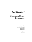
Please follow these steps to add HDD into Orion NAS System
network HDD array.
Figure 2-1 Hard Disk Drive Installation
1. Withdraw the HDD caddy out from Orion NAS System.
2. Place the SATA HDD into the HDD caddy, as shown in Figure 2-1
and secure with the screws provided.
3. Insert the HDD caddy back into Orion NAS System. (Lock if
desired.)
-2-2-
Chapter 2
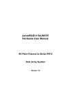
2-3 Network Connection
Orion NAS System supports two Gigabit Ethernet port. Under normal
circumstances, simply connect a network cable from NAS Ethernet to
the switch and it will work.
Eth0
Eth1
Figure 2-2 Connecting Ethernet Port
To properly shutdown the system:
1. Select “Shut Down” from the menu on system LCD display.
2. Alternatively, select “Shut Down” from the administrative page.
3. Immediately turn off the power. Do not exceed 4 seconds. NAS
System supports manual shutdown by using the “Shutdown on
Power Push Button.”
When the system is in normal operation, do not turn off the
power directly from the power source. Otherwise, data that
are in the process of been written on the NAS might be lost
and can not be recovered. For more details, please refer to
section 4-8, system menu.
-2-3-
Chapter 2
2-4 System Bootup—Self Configuration Test
After the power is turned on, System performs Self Configuration Test
automatically. These self tests include CPU Type, CPU Fan, System
Memory Size, Network Control Chip, and Hard Disk Control Chip data,
to ensure normal system operation.
2-5 IP Address
Most system configuration settings can be set via system
administrator control. This administrative control is web browser
based. To access the system administrator control, you must know
the IP Address of Orion NAS System.
Upon first-time bootup, Orion NAS System initiates eth 0 with
DHCP/BOOTP to select all available IP Addresses in network. If
manual input of an IP Address is required, acquire the IP Address
from the system administrator. And then manually type the IP Address
via the front control panel.
Upon first-time bootup, Orion NAS System initiates
DHCP/BOOTP to select all available IP Addresses in network.
If other means of IP Address selection is required, you can
manually type an IP Address via LCD front control panel.
There are three different modes you can choose from (Bond 0, eth 0
and eth 1). In menu here we will take eth 0 as example below. Follow
these steps and manually set the IP Address through the front control
panel:
-2-4-
Chapter 2
1. Press “Enter” key.
2. Input the administrative password and press “Enter” key. (The
default password of this product is eight zeros (00000000). Note:
You may press the “ESC” key to exit at any time). After entering
the eighth zero, press the “ESC” key to finish and it will take you to
the next step.
3. If LAN supports DHCP Server, use automatic detection to
complete configuration.
4. Steps to disable DHCP.
12 CHANNEL0
116 DHCP
Select
126 DHCP STATUS
Press “Enter”
Then Press “Enter”
ON
Then Select
126 DHCP STATUS
ON
Then Press “Enter”
OFF
Use the “▲” up and “▼” down arrows to select “OFF,” then
press “Enter.”
5. Use the “▲” up and “▼” down arrows to select menu items. Select
“1Network” and press “Enter” to confirm.
6. Select “12 Channel 0” and press “Enter” key to confirm.
7. Press “Enter” key again to verify “Channel 0 Status”. Results are
displayed on the LCD front control panel.
121
CH0
Status
ON
CONNECTED
-2-5-
Chapter 2
When a connection is made, a red light just above the left front
panel is visible on the NAS unit. If this light is not visible then the
connection has failed.
8. If the status is “DISCONNECTED,” the connection to Ethernet is
not successful. Please check if the network cable is connected
correctly. After verification, press “Enter” key to check “Channel 0
Status” again. Make sure the connection to network is successful.
Ethernet status won’t be updated automatically! Press “Enter”
key to check “Channel 0 Status” again and make sure the
connection to network is successful.
9. Setup IP address Manually
10. Use the “▲” up and “▼” down arrows to select “112 CH0 IP
ADDR.” Press “Enter” to set the IP Address.
11. Every time you type an IP digit, press “Enter” once before
punching in another digit.
12. Use the “▲” up and “▼” down arrows to select “123CH0
NetMask.” Press “Enter” to set the Sub-network Mask IP Address.
(Optional)
13. Type the Sub-network Mask IP Address. (If not supplied, system
will set to default)
14. Use the “▲” up and “▼” down arrows to select “124CH0
GateWay.” Press “Enter” to set the Gateway IP Address.
(Optional)
15. Type the Gateway IP Address. (If not supplied, system will set to
default).
16. Press “ESC” key 4 times continuously to exit the main menu. At
this moment, the LCD front control panel will display all relevant
information, such as CPU temperature, fan speed, and the set IP
address, etc.
-2-6-
Chapter 2
2-6 Connecting to a Network
When all system configurations are set and connected to the network,
type the IP Address via an internet browser (e.g. Internet Explorer) to
access the system administrative web page and complete all
administrative tasks.
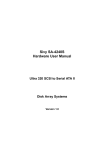
2-7 Administrator Login
Figure 2-3 shows the login screen of Orion NAS System network HDD
array after the IP address has been entered on the Web browser
address line. The table below shows the initial factory default for the
administrator gain access to the system.
Default administrator password
User Name
nasroot
Password
00000000
After typing in the administrator user name and password, press “Go”
symbol on the login page or just simply hit “enter/return” key on
Keyboard.
Figure 2-3 Orion NAS System Login Screen
-2-7-
Chapter 2
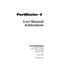
2-8 System Information Screen
Figure 2-4 shows the display screen after logging in as the
administrator. There are 2 parts in the screen:
1 System Information area: The configuration area for
administrator. Including: changing
settings, statistics records, shared
data, and storage space, etc.
2 Menu area:
Select desired tasks to perform form
menu area.
Figure 2-4 Display after Logged in as Administrator
-2-8-
Chapter 2
2-9 Quick Configuration
Figure 2-5 shows the Quick Configuration screen. Initial configurations
may be set through this screen.
Figure 2-5 Quick Configuration Screen
-2-9-
Chapter 2
2-10 Server Name
The server name must be unique. If there are other servers in the
network environment, please make sure the name is not repeated.
Length of the name should not exceed 14 characters, and should not
contain any space.
Figure 2-6 shows the server name settings. After typing in the name,
there are 2 more options available:
1. Update and Next: System will store settings and go to the next
setting screen.
2. Next:
System will ignore any changes and go directly
to the next setting screen.
Figure 2-6 Server Name
Type in the server name and click “Update and Next.” System stores
new settings and returns the updated status. Confirm that the system
prompts “Changed Successfully” is showing and then click “Next”
button.
Figure 2-7 shows the system prompt information.
Figure 2-7 System Prompt Information
-2-10-
Chapter 2
2-11 Date, Time, and Region
Figure 2-8 shows the settings of date, time, and region as well as NTP
option.
If your location is not in the list, please select a city that is the nearest
and within the same time zone.
Figure 2-8 Settings of Date, Time, and Region
When settings are done, click “Update and Next” to proceed to the
next screen.
-2-11-
Chapter 2
2-12 Network Settings
Figure 2-9 shows the settings screen of network port. From the
pull-down menu, you may select the system IP address as
“DHCP/BOOTP Obtain an IP Address Automatically” or “Manual.”
Figure 2-9 Settings of Network Port
The system will automatically select a physical network port that is
available and auto-sense the speed of the network. If manual setting
is desired, select “Manual” from the pull-down menu, instead of
“DHCP/BOOTP Obtain an IP Address Automatically.”
When settings are done, click “Reboot” to proceed to the next screen
and restart the NAS system using the changes. Clicking “OK” button
saves the changes and exit this screen allowing the administrator to
continue making other changes. Only when the system is rebooted
will any changes be activated.
Figure 2-10 Network Device Setup Successfully
-2-12-
Chapter 2
2-13 Adding Storage Volume
Upon first-time system configuration, there will be no existing storage
volume. Figure 2-11 shows the system prompt.
Figure 2-11 No Storage Volume Existed in System
Before setting the system as an array storage system, you have to
setup at least one storage volume. Click “Add” button, and go to
Storage Volume Settings screen.
2-13-1 Storage Volume Settings
The system supports multiple storage volumes and each storage
volume can be set as JBOD, RAID-0, 1, 3 or 5.
A storage volume itself can be a single HDD (JBOD mode) without
any RAID support. A storage volume (RAID 1, 3 or 5) may be
assigned a backup HDD, to automatically replace any damaged HDD
in storage volume.
If the number of unused HDD is less than the number required by a
specific storage volume option, then the storage volume option will
not be available. The following figure shows minimum required
number of HDD for all options.
Storage Volume Type
Minimum HDD
Number Required
Single HDD (No array)
RAID-0 (Disk Striping)
RAID-1 (Disk Mirroring)
RAID-3 (Disk Striping with parity)
RAID-5 (Disk Striping with parity)
1
2
2
3
3
-2-13-
Chapter 2
2-13-2 Single HDD Storage Volume:
This mode does not have array support and only supports single HDD.
Figure 2-12 shows the screen when Single HDD Option is used.
Figure 2-12 Single HDD Storage Volume
On the left of screen, lists all HDD that are installed in the system but
not configured as storage volume yet.
Select desired HDD and click the “Δ right arrow button to make it a
single HDD storage volume. If you change your mind, click the “Í”
left arrow button to put it back to the unused HDD list.
When settings are done, click the “OK” button.
To cancel the single HDD storage volume settings, click “Cancel” or
“Back.”
-2-14-
Chapter 2
2-13-3 RAID-0 Storage Volume—Disk Striping
Figure 2-13 shows the screen when RAID-0 Option is used.
Figure 2-13 RAID-0 Storage Volume
1.
Available HDD
A list of all HDD that are installed in the system but not configured
as storage volume yet.
2. RAID HDD
Select desired HDD and click the “Δ right arrow button to add it
into the RAID-0 storage volume. If you change your mind, click the
“Í” left arrow button to put it back to the unused HDD list.
3. Stripe Size
Maximize the performance of sequential file in the storage volume.
There is no need to change the settings in general, unless the
advanced administrator has special file storage layout in the
storage volume.
-2-15-
Chapter 2
4. When settings are done, click “OK” button.
A single HDD can not support RAID-0. It requires at least 2
HDD.
RAID-0 does not have any safety features, such as “Data
Synchronization” and “Automatic Data Recovery.”
-2-16-
Chapter 2
2-13-4 RAID-1 Storage Volume—Disk Mirroring
Figure 2-14 shows the screen when RAID-1 Option is used.
Figure 2-14 RAID-1 Storage Volume
1. Available HDD
A list of all HDD that are installed in the system but not configured
as storage volume yet.
2. RAID HDD
A list of all HDD that are already added into this storage volume. To
add a HDD, click the “Δ right arrow button to add it into the
RAID-1 storage volume.
3. Backup HDD
Shows the designated replacement HDD in the storage volume.
(The backup HDD for any damaged HDD)
RAID-1 supports 2 or 4 HDD.
-2-17-
Chapter 2
2-13-5 RAID-3 Storage Volume—Disk Striping with Parity
This RAID-3 feature is unique to the Orion family of NAS and is the
first to be available in this type of product. While RAID-3 is similar to
RAID-5, this feature is different in that it does not have a stripe size
option. RAID-3 is most efficient for single user who is working with
large files. When multiple users require access to the NAS and
smaller file sizes, it is more efficient to utilize a RAID-5 system.
Figure 2-15 shows the screen when RAID-3 Option is used.
Figure 2-15 RAID-3 Storage Volume
1. Available HDD
A list of all HDD that are installed in the system but not configured
as storage volume yet.
2. RAID HDD
A list of all HDD that are already added into the storage volume. To
add a HDD, click the “Δ right arrow button to add it into the
RAID-5 storage volume.
-2-18-
Chapter 2
3. Backup HDD
Shows the designated replacement HDD in the storage volume.
(The backup HDD for a damaged HDD)
When settings are done, click the “OK” button. If you change your
mind, click the “Í” left arrow button to put it back to the unused HDD
list.
-2-19-
Chapter 2
2-13-6 RAID-5 Storage Volume—Disk Striping with
Distributed Parity
Figure 2-16 shows the screen when RAID-5 Option is used.
Figure 2-16 RAID-5 Storage Volume
1. Available HDD
A list of all HDD those are installed in the system but not configured
as storage volume yet.
2. RAID HDD
A list of all HDD those are already added into the storage volume.
To add a HDD, click the “Δ right arrow button to add it into the
RAID-5 storage volume.
3. Backup HDD
Shows the designated replacement HDD in the storage volume.
(The backup HDD for a damaged HDD)
-2-20-
Chapter 2
4. Stripe Size: Please refer to 2-13-3.
When settings are done, click the “OK” button. If you change your
mind, click the “Í” left arrow button to put it back to the unused HDD
list.
2-13-7 Building Up Storage Volume
Figure 2-17 shows the progress screen, when the system is building
up a storage volume.
Figure 2-17 Storage Volume Status Table
System is setting up file system and building up storage
volume. Please wait until it reaches 100%, as shown in figure
2-17.
-2-21-
Chapter 2
2-13-8 Multiple Storage Volumes
Figure 2-18 shows a list of all storage volumes that are established in
the system.
Figure 2-18 List Of All Storage Volumes
The system supports multiple storage volumes. To add a new storage
volume, simply click on “Add” button and complete its settings. When
settings are done, click on “Next” to proceed to next screen.
RAID-3, 5 requires a minimum of 3 HDD.
RAID-1, 3, 5 allows only one disconnected or damaged
HDD. If 2 HDD are disconnected, HDD array will be
damaged.
After the system has initiated the RAID build process, you
may set the initialization speed to increase RAID
Synchronization to save time, as shown in figure 2-19.
-2-22-
Chapter 2
To change the speed of the initial Build up or rebuilding, select the
storage volume and it will be highlighted in yellow. Click on the Modify
Button and you may change rebuilding speed or backup HDD of the
system, as shown in figure 2-19. This feature is only available when in
the initial or rebuilding process.
Figure 2-19 Modifying Storage Volume
-2-23-
Chapter 2
2-14 Enabling Windows Network Service
The last item in the Configuration process is Network Setup. Click on
the Network Setup on the Menu area. This will display the set up
features for the different type of clients. The example below is to set
up Windows clients. Click on the Windows tab and it will display the
screen for setting Windows Clients “Enable Windows Network
Settings.” The settings screen is shown in figure 2-20.
Figure 2-20 Windows Network Settings
-2-24-
Chapter 2
Figure 2-21 shows the pop-up screen after selecting “Update” button.
Figure 2-21 Windows Network Settings Updated Successfully
The system supports Windows SMB network communication protocol,
to enable data sharing between clients with Windows related
operating platforms. This page provides settings for related
parameters.
If Windows Network Service is not being used in the system,
select disable for this option. Then select a desired network
type from ”Network Setup”.
1. Status
To enable Windows network service, please select “Enable” and vice
versa
2. Security Level
Select any of the following security levels for applying to the system:
-2-25-
Chapter 2
A. User Level
All system user accounts must be created within the system.
The system administrator must manually create each user and
assign it a password, as well as set a privilege level for
accessing shared folders in a storage volume.
Workgroup
Input a workgroup name in this field. The
workgroup is the one in which you would like
to add the system in the Windows network
environment.
Server Description Input a description details to appear this NAS
server under selected workgroup.
Figure 2-22
Please input the short Domain name only for associated field.
For example if the full domain name is “Orion.com” then
“Orion” will be the only input required.
-2-26-
Chapter 2
B. Domain Level: If the network environment is to access user
information via a Windows NT Server Primary Domain
Controller (PDC), the system will automatically obtain the user
names and passwords from the PDC. As shown in figure 2-23,
the pop-up screen after setting the security level as “Domain
Level” and clicking the “Update” button.
Domain
Input the selected Domain name here.
PDC Name
Input the PDC name for selected
domain.
PDC Administrator Input the domain’s administrator name
Name
here.
PDC Administrator Input the domain administrator’s
password
password.
uid range
The user UIDs used in 820SR for
Domain users to tell from those ones
created locally.
gid range
The group GIDs used in 820SR for
Domain users to tell from those ones
created locally.
Server Description Input a description details to appear
this NAS server under selected
Domain.
-2-27-
Chapter 2
Figure 2-23
-2-28-
Chapter 2
C. ADS Level: If the network environment is to access user
information via a Windows Server 2000 or Windows Server
2003 Active Directory Service (ADS), the system will
automatically obtain the user names and passwords from
selected DC. As shown in figure 2-24, the pop-up screen after
setting the security level as “ADS Level” and clicking the
“Update” button.
Domain
Input the selected AD Domain name
here.
ADDC Administrator Input the ADDC administrator name.
Name
ADDC Administrator Input the ADDC administrator’s
password
password.
uid range
The user UIDs used in 820SR for
Domain users to tell from those ones
created locally.
gid range
The group GIDs used in 820SR for
Domain users to tell from those ones
created locally.
Server Description
Input a description details to appear
this NAS server under selected
ADDC.
-2-29-
Chapter 2
Figure 2-24 Domain or ADS Level Settings
3. WINS server IP
Input the WINS server IP here if it is applicable.
4. Complete Configuration Process
When Windows Security Level settings are done, click “Update and
Next” button to complete all settings in the menu.
5. Other Network Clients
Refer section 3-5-3 for Unix Clients, section 3-5-4 for Apple Clients,
section 3-5-5 for FTP clients.
The system configuration is done now and is ready to serve online as
a network attached storage device with redundant HDD array.
-2-30-
Chapter 3
Chapter 3
Using Administrative Tools For
Administrator
Orion NAS System administrative tools for administrator can be
accessed completely via web browser. Its powerful menu allows the
administrator to complete system configuration settings and manage
the system easily.
Using “System Menu” to set and control the system is covered in this
chapter.
3-1 Login
Enter the IP Address via a web browser and get into the configuration
settings of Orion NAS System network HDD array.
To look up the IP Address of the system, the administrator can directly
view the displayed contents of the system control panel, or use the
complementary search software of the system to acquire it.
The default user name and password of the server administrator.
User Name
nasroot
Password
00000000 (8 consecutive 0’s)
Password Length: Should not exceed 14 characters, and
may include English alphabet. Password is case-sensitive.
The entered password must be identical to the original
setting, or you will not be able to login to the system.
-3-1-
Chapter 3
3-2 Administrator Login
After a user is logged into Orion NAS System as the administrator,
he/she will have full privilege over the network HDD array.
Figure 3-1 shows the system option menus that are configurable by
the administrator.
Figure 3-1 Administrator System Option Menus
3-3 Quick Configuration
The system administrator can set primary parameters of Orion NAS
System by using this menu, hence enable basic system operations.
Each setting is enabled by hitting the update & next button. If no
changes are required, then step to the next screen by hitting the
“next” button. For more details about settings, please refer to chapter
2 and related chapters.
-3-2-
Chapter 3
3-4 System Setups
This menu is used to change related parameter settings. Figure 3-2 is
the overview of System Configuration.
Figure 3-2 System Settings Overview
The system settings menu is as shown in figure 3-3.
Figure 3-3 Options of System Settings Menu
-3-3-
Chapter 3
3-4-1 Server Name
Figure 3-4 shows the server name setting screen.
Figure 3-4 Server Name Setting
3-4-2 Password
It is allowed the administrator to change the password for entering
system administrative page. Please refer to figure 3-5.
Figure 3-5 Server Password Setting
To change system password, a user must type exactly the original
system password. And then type the same new password twice to
successfully change the system login password.
Password Length: Should not exceed 14 characters, and
may include English alphabet. Password is case-sensitive.
The entered password must be identical to the original
setting, or you will not be able to login to the system.
-3-4-
Chapter 3
3-4-3 Language
The system language menu option has offered 6 different choices;
Web-browser default, English, Traditional Chinese, Simplified
Chinese and Japanese and Korea language.)
The administrator should set the language option as the same
language as the one currently used by OS.
Figure 3-6 Language Setting Screen
3-4-4 Time Setting
Please refer to section 2-11 of the manual to set time, date, region,
and city.
-3-5-
Chapter 3
3-4-5 System Event Reports
Figure 3-7 shows event reports option. The administrator may set up
to 3 e-mail addresses here by using this option. When any system
event occurs, it will automatically send a warning e-mail message to
all 3 e-mail addresses.
Figure 3-7 Event Reports Screen
To use the event reports option, the followings must be set first:
1. BEEP Status
By default, “Enable” option is selected. When event occurs, the
system sends a “beep” to notify the administrator.
-3-6-
Chapter 3
2. SMTP Status
To enable automatic message delivery, select “Enable” option.
Figure 3-8 SMTP Status Settings
If “Sender E-Mail Address” is not set and “Default” is used, messages
will be transferred by MaxTronic E-Mail to “E-Mail Address 1~3 of The
Administrator.” It is recommended to change “Default” to the E-Mail
Address of The MIS Administrator.
3. Mail Server Address
Enter the IP Address of SMTP server and the mail server name.
4. E-Mail Address 1~3 of The Administrator
Enter e-mail addresses of the administrator here. The system will
automatically send out system messages to the e-mail addresses
that you have set.
-3-7-
Chapter 3
5. Send a Test E-Mail
If “Yes” is selected, the system sends a “test” e-mail to the
configured e-mail address(es) after “Update” button is clicked to
make sure proper delivery of report messages.
Figure 3-9 Send a Testing E-Mail
After select “Yes” for “Send a Test E-Mail,” click “Update.” A test
e-mail will be sent to the configured e-mail address(es).
Figure 3-10 Testing E-Mail Sent Screen
-3-8-
Chapter 3
3-4-6 SNMP Settings
Figure 3-11 shows the SNMP Settings screen.
Figure 3-11 SNMP Settings
To enable SNMP, the following parameters are required:
1. SNMP Status
To use SNMP function, set its status as “Enable.”
2. Authentication notice.
3. Community
Enter a NAS community name.
4. Trap Community
Enter a Trap Community name.
5. IP Address of Trap Community
The IP address of Trap Receiving end to receive all notifications.
6. System Administrator Name
Enter a SNMP system administrator name of the system. The
name does not have to be the same as the system administrator.
7. NAS Location
Enter an easily identifiable NAS location.
-3-9-
Chapter 3
3-4-7 System Configuration Backup
As shown in figure 3-12, the administrator is allowed to backup or
restore configuration settings of the system.
Figure 3-12 Backup and Recovery Of System Settings
The administrator may make backup files or restore previous
configuration settings. These include:
1. Contents of Raid Configuration
2. Settings of NFS
3. Settings of Windows SMB
4. Settings of Apple Talk
5. User Database (including user name, password, quota, and group)
When the system administrator has completed all settings
and layouts, it is strongly recommended to make a backup
and store it for emergency situations.
-3-10-
Chapter 3
When “OK” is clicked (figure 3-12), the system prompts a dialog box,
as shown in figure 3-13, and asks for the administrator password.
Figure 3-13 Enter Password
Enter the “User Name” of administrator in associated field, and enter
the password in “Password” field to complete backup (or restore)
system settings. This will now save a backup file to the HDD of the
computer in which the administrator is using to access the NAS.
This is usually in the form of “NameofNAS_config.bin”
When backing up settings of the system, a directory must be specified
to save backup files. When restoring system settings, the directory
must be provided to access backup files. This is accessed by
selecting the restore button and hitting the browse button. When the
file is located, selecting the file and click OK. This will show up on the
location window. Clicking OK button will restore the previous
configuration.
-3-11-
Chapter 3
3-4-8 Restore Default Settings
Figure 3-14 shows the menu to restore default settings.
Figure 3-14 Restore Default Settings
This option reverts to the factory default settings of the system. Before
proceeding with this option, please be sure to perform backup of the
configuration file. Otherwise, all settings (e.g., groups, users, user
quotas, user privileges, network settings) will be erased and reset to
default values. This will only happen if the drives are still installed. If
the drives have been removed, this process will only refresh the
NVRAM. This has the action of making the unit like a brand new
system. When the drives are re-inserted, the configuration will be
restored from the drives set. Otherwise, a restore function from a
backup file is required.
All system settings, groups, users, user quotas and privileges
will be erased.
Once this option is confirmed and executed, there is no way
to retrieve any previous data except from a saved backup file
-3-12-
Chapter 3
3-4-9 Using UPS for System
The UPS setting screen of the system is shown in figure 3-15.
Figure 3-15 UPS settings
This page provides tools to configure the Orion 820SR to monitor
UPS device.
•
UPS Watch
This radio button group enables/disables UPS watch function of
the system.
•
UPS Selection
The system supports [APC Back-UPS ES 500(RS-232) and
APC Smart UPS].
•
Time to shutdown
If enable the UPS watch option, the default delay of shutdown is
5 minutes. Otherwise, the system will be shutdown immediately
when a power loss has been detected.
-3-13-
Chapter 3
•
Detailed Watch
If this option has been set to "Yes", the system will shutdown
automatically if remaining battery charge below 5% on UPS or
battery runtime below 5 minutes on UPS.
•
Send message to connecting clients
If this option has been set to "Yes", the system will send
message to connecting clients when each power event has
been detected.
•
Update
The system saves all changes if this button is pressed.
•
Cancel
The system skips all the modifications if this button is pressed.
-3-14-
Chapter 3
3-4-10 System Firmware Upgrade
The firmware upgrade screen of the system is shown in figure 3-16.
Figure 3-16 Firmware Upgrade
The administrator may acquire the latest version of firmware and save
it in local HDD. By using this menu option, provide the file location to
the system and complete firmware upgrade.
Please contact your local dealer regularly to acquire the latest version
of firmware. The file will be in a form that looks like “1.01k-NAS
System.bin”. Locate the file using the Browse button and click “OK”.
It will update the firmware automatically and when completed, the unit
will ask you to reboot.
If the settings are not saved, please check the battery on the
Motherboard. It may require replacement
-3-15-
Chapter 3
3-5 Network Settings
Network option menu is used to set related network parameters of the
system. Figure 3-17 shows current network status of the system.
Optional
Figure 3-17: Network Status Display
The displayed contents of each network interface include:
1 Attach:
Display connection status of network
interface.
2 IP Setting Type:
Display IP Setting Type of network
interface, manual or automatic (using
DHCP/BOOTP).
3 IP Address:
Display the IP Address of network
connection.
4 Subnet Mask:
Display settings of sub network mask.
5 Gateway:
Display settings of Gateway. (Optional)
6 DNS Server:
In general, no need to set. (Optional)
7 MAC Address:
Display the address of MAC layer.
8 Current Speed:
Normally is 100~1,000 Mb/s, differentiated
by Switch.
-3-16-
Chapter 3
The contents of network settings menu is shown in figure 3-18.
Figure 3-18 Network Settings Menu
3-5-1 Basic Settings
Figure 3-19 Network Basic Settings
Figure 3-19 provides tools to setup the network of the system. Two
physical network adapters are provided in this system, and a logical
channel bonding interface is supported to bond 2 Ethernet port
together.
-3-17-
Chapter 3
Network
Adapter
There are 2 physical Ethernet adapters (eth 0 and
eth 1) and one logical channel bonding interface
(Bonding) in this system. If "Bonding" is
selected, channel bonding function is enabled that
two physical Ethernet adapters are in bond, and
the network bandwidth may be doubled; otherwise
select a single adapter ("Ether0" or "Ether1") as
your Ethernet interface.
Setting
This select list displays current setting of the
selected [Network Adapter]. [IP Address], [Subnet
Mask], and [Gateway] will be disabled if this select
list is "DHCP/BOOTP". Otherwise, specify them
manually in the following 3 text fields respectively.
IP Address
This text field displays current IP address of this
system. If "DHCP/BOOTP" is selected in [Setting],
the text field will be disabled and IP address is
assigned tomatically/dynamically depends on
your network environment.
Subnet Mask This text field displays current subnet mask of the
system If "DHCP/BOOTP" is selected in [Setting],
the text field will be disabled and subnet mask is
assigned automatically/dynamically depends on
your network environment.
Gateway
This text field displays current gateway of this
system. If "DHCP/BOOTP" is selected in [Setting],
the text field will be disabled and gateway is
assigned automatically/dynamically depends on
your network environment.
-3-18-
Chapter 3
Mode
The bonding mode. This select list exists only if
the [Network Adapter] is "Bonding". There are 3
bonding mode: Trunking, Fail-over and ALB,
where Trunking means the network bandwidth is
doubled from bonding 2 physical Ethernet
adapter, Fail-over stands for only one of the two
physical adapters is in use and the other is a
spare adapter and ALB can dynamically manage
2 physical Ethernet adapter, distribute the load
among them by constantly analyzing the traffic
flow from the server.
Speed
This select list displays current network speed.
There are 6 possible speed: Auto, 10 Mb/s, Half
Duplex, 10 Mb/s, Full Duplex, 100 Mb/s, Half
Duplex, 100 Mb/s, Full Duplex, and 1000 Mb/s,
Full Duplex.
DNS Server
This text field displays the IP address of the DNS
(Domain Name Server).
Update
The system saves all modifications if this button is
pressed.
Cancel
The system skips all modifications if this button is
pressed.
-3-19-
Chapter 3
3-5-2 Windows
The system supports Windows SMB network communication protocol
to enable data sharing between clients with Windows related
operating platforms. Please refer to section 2-14 for related parameter
settings.
3-5-3 Unix
The system supports UNIX compatible operating platforms to enable
data sharing between clients with NFS communication protocol. This
page provides related parameter settings and is shown in figure 3-20.
Figure 3-20 Enable UNIX Compatible Network Service
The system provides NIS Client Service to allow itself to be added into
the NIS domain. Check the “Enable NIS domain” box to enable it and
enter NIS function parameter name. When completed, select
“Update” button to save the changes. Select “Cancel” to disregard any
changes made.
-3-20-
Chapter 3
Select “Share Setup” of “Storage Setup” to make share folder
available to Unix/Linux clients as shown in figure 3-21.
Figure 3-21 Make share folder for Unix/Linux clients
-3-21-
Chapter 3
Next, select “Privilege” in “User Privilege” to choose the share folder
to be made for Unix/Linux clients, and enable the “Unix” client to add
NFS client privileges, see figure 3-22 and 3-23.
Figure 3-22 Select the folder made for Unix/Linux clients
Figure 3-23 Enable the “Unix” box to add NFS privilege
-3-22-
Chapter 3
Set up the “Host name”, “Privilege” and “Root access” and the setup
is shown in figure 3-24.
Figure 3-24 Settings of NFS Clients Privilege
Currently, only NFS V2 and V3 are supported.
-3-23-
Chapter 3
Use “mount” command from NFS clients to mount the Orion NAS, as
shown in figure 3-25.
Figure 3-25 Mount the NAS file system from NFS clients
mount
command to mount file system
-t nfs
indicate the file system type to NFS
192.168.1.102
the IP address of NAS
:/shares/Volume1/test the path of the share folder made for NFS
clients on NAS system
/test
refers to the root of the file system on device
-3-24-
Chapter 3
Use “df” to check the mounted device, as shown in figure 3-26
Figure 3-26 check the mounted device
Use “umount” to dismount the NAS system, as shown in figure 3-27
Figure 3-27 Dismount the NAS system
-3-25-
Chapter 3
3-5-4 Apple
The system supports Apple Talk communication protocol to enable
data sharing between clients with Mac OS operating platform. This
page provides settings of related parameters and displays in figure
3-28.
When Apple Talk network service is enabled, the administrator must
provide a zone name. When completed, select “Update” button to
save the changes. Select “Cancel” to disregard any changes made.
Figure 3-28 Enable Apple Network Service
-3-26-
Chapter 3
3-5-4-1 OS 9.2.2
1. Setup the “TCP/IP” of “Control Panels”, as shown in figure 3-29.
Figure 3-29
-3-27-
Chapter 3
2. If there is a DHCP server, turn on the DHCP and make sure the
setup of IP section and Subnet mask is the same as the NAS
system, as shown in figure 3-30
Figure 3-30
3. Please click on the Apple Icon on the top left hand corner and
select the “Chooser” to connect to the NAS as shown in figure
3-31
Figure 3-31
-3-28-
Chapter 3
4. After selecting the Chooser, please select AppleShare and you can
see the Select a file server at the right-hand side. Please note that
you must select “Active” for AppleTalk which is located at the
bottom right-hand side. Otherwise, you won't be able to see the
computer server name in the right side as shown in figure 3-32
Figure 3-32 Enable active of AppleTalk network services
-3-29-
Chapter 3
5. Select the appropriate server by highlighting it and click the OK
button in figure 3-33
Figure 3-33
-3-30-
Chapter 3
6. Please select how you would like to login, that is as a “Guest” or as
a “Registered User”. If "GUEST" is selected as the preferred login
in the NAS, then you can use "GUEST" as your login name as
shown in figure 3-34
Figure 3-34
-3-31-
Chapter 3
7. Entering the NAS as a GUEST, the status will elect the share table
of contents as shown in figure 3-35
Figure 3-35
8. After selecting the items required, you will see the shared folder as
a server icon on your desktop as shown in figure 3-36。
Figure 3-36
-3-32-
Chapter 3
9. Click on the shared item, use the command key (which is located
next to the space bar) + “I” (Command + I or “Get Info” Short Cut)
to check the share item condition (figure 3-37). You can see it is
using TCP/IP mode as red zone's connecting method, and at the
ICON, it will show an earth icon at the bottom of the disk drive
Figure 3-37
-3-33-
Chapter 3
3-5-4-2 OS X
1. Set up the Network settings from the “System Preferences”. As
shown in figure 3-38.
Figure 3-38 Network Settings of System Preferences
-3-34-
Chapter 3
2. Make sure that the IP section is the same as the NAS system.
Otherwise, the performance will be impacted. See figure 3-39.
Figure 3-39 Status of DHCP
-3-35-
Chapter 3
3. Enable the “Make AppleTalk Active” box by checking it with a ‘tick”,
as shown in figure 3-40.
Figure 3-40 Settings of AppleTalk
-3-36-
Chapter 3
The name of the Server will appear on the left side of the screen of
“Connect to Server” as Shown as figure 3-41. In this case, the top icon
in the Connect to Server screen
Figure 3-41 Connect to Server with AppleTalk
If “Make AppleTalk Active” is unchecked as shown in figure
3-42, the screen of “Connect to Server” will look like figure
3-43; The Server icon and name will not appear to enable
AppleTalk connection.
-3-37-
Chapter 3
Figure 3-42 Default of OS X
Figure 3-43 Connect to Server without AppleTalk
-3-38-
Chapter 3
4. Select “Connect to Server” from “Go” on the top function bar of OS
X, as shown in figure 3-44. There are two type of protocol to
connect to the server; AppleTalk and SMB. A higher performance
of network transmission is possible with AppleTalk than using SMB.
Click “*” on the “Connect to Server” screen and you will see the
server name on right side of the window, as shown on figure 3-45.
Figure 3-44
Figure 3-45
-3-39-
Chapter 3
5. Click the name of NAS system to highlight it, the AFP connect type
will been shown in bottom of the screen, as shown in figure 3-46.
Figure 3-46 Connect to NAS system by AppleTalk
6. Click on the “Connect” button and the log on screen will appear, as
shown in figure 3-47. Log-in as per your user name and password
assigned by the Administrator.
Figure 3-47
-3-40-
Chapter 3
7. Then the volume of NAS system will be shown as figure 3-48.
Figure 3-48 Volume of NAS system
8. Choose the appropriate volume and click “OK”, the volume will be
shown on desktop as shown in figure 3-49.
Figure 3-49
-3-41-
Chapter 3
9. The operation of using Samba to connect NAS system is similar to
using AppleTalk. Select “WORKGROUP” (Default) in the “Connect
to Server” screen, as shown in figure 3-50.
Figure 3-50 Select “WORKGROUP” to use Samba
-3-42-
Chapter 3
10. Select the name of NAS system by highlighting it, the Samba
connection mode will be shown in of the “address” space at the
bottom of the screen, (see figure 3-51).
Figure 3-51 Connect to NAS system by Samba
11. Click “Connect” and select share folder, as shown in figure 3-52
Figure 3-52 Share Folder of NAS system
-3-43-
Chapter 3
12. Click “OK” and the Authentication screen will be displayed, as
shown in figure 3-53.
Figure 3-53 SMB/CIFS Authentication Screen
13. After entering the Username and Password, the shared folder will
be displayed on the desktop (figure 3-54).
Figure 3-54
-3-44-
Chapter 3
3-6 Storage Volume Settings
Storage volume settings menu allows the administrator to configure
various settings according to required environment-specific storage
mode. The screen after storage mode is set is shown in figure 3-55.
Figure 3-55 Contents of Storage Volume Settings Menu
Storage Volume information includes the used HDD name, type,
capacity, and related information. The content of a storage volume
may be: (1) a single HDD, or (2) a RAID system which is made up with
multiple HDDs.
-3-45-
Chapter 3
3-6-1 HDD Information
On the upper half of figure 3-55, lists all used HDD. Its contents
include:
(1) Name:
Display the name of HDD in system.
(2) Model:
Display HDD model.
(3) Capacity: Display the capacity of HDD.
(4) Status:
The location of the storage volume.
3-6-2 Storage Volume Information:
On the lower half of figure 3-55, lists related information of all
established storage volumes. Its contents include:
(1) Name:
Display storage volume name.
(2) Type:
Display storage volume type.
(3) Capacity:
Display storage volume capacity.
(4) Used Space (MB): Display amount of space of storage
volume in use.
(5) RAID HDD:
Includes one or more HDD. Display the
HDD combination used by storage
volume.
(6) Status:
The displayed status can be one of the
following six items:
Not Used
The storage volume is not in use.
In Use
The storage volume is in normal operation.
When the system is setup for the first time or is
shut down abnormally, if there is any RAID-1 or
RAID-5 setup in storage volume, the system will
Data
automatically duplicate backup data in RAID-1.
Synchronization
For RAID-5 setup, the system performs
synchronization on storage volume data,
according to the associated location of parity bit.
-3-46-
Chapter 3
Data
Recovering
The system supports RAID-1 and RAID-5
hot-swap. When storage volume setup is any of
these two types, after the replacement of any
HDD, the system automatically rebuilds all data
in the original HDD.
The basic concept is equivalent to data
synchronization. But if another storage volume is
Data
performing data synchronization, actions of the
Synchronization
storage volume will be delayed until the
Delayed
operation of former storage volume is
completed.
Formatting
Storage volume is formatting mode. The
progress status will be displayed in this field.
To see more details pertaining a storage volume, double click on the
“Storage Volume Name.” Figure 3-56 displays detailed information of
a storage volume.
Figure 3-56 Detailed Information of A Storage Volume
-3-47-
Chapter 3
3-6-3 Storage Volume Settings Menu
Figure 3-57 displays options of storage volume settings menu and
Figure 3-58 shows storage information installed in system currently.
Figure 3-57 Options of Storage Volume Settings Menu
Figure 3-58 Storage Information
-3-48-
Chapter 3
Double click on installed disk and the disk information screen appear
below as Figure 3-59.
Figure 3-59 Disk Information
ICRC
it is the acronym of “Interface Cyclic Redundancy Check”.
ICRC error indicates there is data error during the data
transmission between hard disk and the controller. When
CRC error occurs, read/write command will retry again.
The greater the number is, the more unstable the
hardware is.
UNC
Indicates that uncorrectable data error happened after
retries, mostly due to media error.
IDNF
a requested address is outside user accessible range.
ABRT Unsuccessful commands which has been dropped out.
-3-49-
Chapter 3
All error numbers will be reset to zero after system reboot.
The Orion NAS has supporting bad sector remapping feature with the
bad block up to 384, system will warning by buzzer for attention. With
bad sector counting up to 512 then the hard disk will be kick out by
system automatically.
We are strongly recommend when the bad sector count has
up to 384 and alarm by system. Please replace the hard disk
in very short time to prevent any data lose.
-3-50-
Chapter 3
3-6-4 Storage Volume Layout
Figure 3-60 shows the options of storage volume layout menu.
Figure 3-60 Storage Volume Layout Menu
Any storage volume is formed by logic means. The formation is either
a single HDD or an array formed by multiple HDD.
This page displays related information of a storage volume and
provides options for storage volume settings.
(1)
Add:
Create a new storage volume.
(2)
Delete:
Select a storage volume and click “Delete” to
delete the storage volume.
(3)
Modify:
Select a storage volume and click “Modify” to
modify required fields. This mode allows only the
rebuilding speed to be changed.
(4)
Format:
Formats a selected storage volume.
-3-51-
Chapter 3
Figure 3-61 Alter “Rebuilding Speed” in modify storage volume option
To make any changes, the volume must first be highlighted and the
relevant option selected. The “Modify” mode can only be selected
during initial volume build up or in rebuilding mode. Figure 3-61 Alter
“Rebuilding Speed” in modify storage volume option
-3-52-
Chapter 3
3-6-5 Folder Layout
This menu applies to folders in a storage volume and stores them in a
cross-platform network to allow access of clients using SMB, NFS, or
Apple Talk. Figure 3-62 shows the full view of folder contents.
Figure 3-62 Full View of Folder Contents
If there is no normal operational storage volume created in the system,
a data folder can not be created.
-3-53-
Chapter 3
Figure 3-63 shows “Add Folder” option in the system.
Figure 3-63 Create Data Folder
The following parameters must be set to create a new data folder:
(1) Name:
The name, which is entered, is the
physical name of the folder that will be
displayed on the system.
(2) Storage Volume:
Select the folder and put it in any created
storage volume.
(3) Path:
The actual path, where the folder is stored
in a storage volume.
(4) Comment:
Comments for the created folder, its
contents will be displayed in the network
environment.
(5) Default Access
Privilege:
Set the default access mode as “Write” or
“Read-Only.”
-3-54-
Chapter 3
3-6-6 N-Sync Setup
N-Sync is a share level replication utility based on rsync tool. Like
rsync, N-Sync's client-server architecture makes replication of files/
folders easier from local share to remote share and vice versa (from
source to destination). An enabled/disabled switch for N-Sync server
could be set by administrator to choose to export N-Sync modules to
clients or not. Administrator could also choose to replicate shares
immediately or by scheduler. N-Sync setup has provided four N-Sync
utilities (Server, Client, Scheduler and N-Sync log). Please refer the
figure below for each utility’s illustrate.
Server:
Figure 3-64
An N-Sync server exports share modules to the remote N-Sync client
to be replicated through rsync protocol. Because of using rsync
protocol, any client that uses rsync tool is able to replicate shares
from N-Sync server.
-3-55-
Chapter 3
Enable
Enable N-Sync Server. (Only the server which is
enabled will be shown in N-Sync client server list.)
Disable
Disable N-Sync Server.
Name
Share name of the system that is exported by
N-Sync server.
Path
Share path of the system.
Comment
Comment of the share.
Read only
Checked for exporting as read only module to the
remote N-Sync/rsync client.
Update
Update changes that are just made.
Cancel
Cancel the changes.
Client:
Figure 3-65
-3-56-
Chapter 3
An N-Sync client is an rsync based utility that allows administrator to
replicate files/folders between local share and remote N-Sync share.
Server Name (list)
N-Sync servers which are available in LAN.
Server Password
Password of remote N-Sync server.
Login
Connect to the selected N-Sync server and
authenticate with server password.
Server Name
Remote N-Sync server to which we are
currently connected.
IP Address
IP address of the remote N-Sync server.
Local Shares (list)
Local shares.
Sync-OP
Synchronize operations including
synchronize from local share to remote
share (=>) and from remote share to local
share (<=).
Remote Shares
(list)
Remote shares.
N-Sync Status
Statistic of selected local share and remote
share.
Used Space
Space currently used by files/folders.
Total Space
Total space of the share.
Status
N-Sync status, messages, or returned error
codes of N-Sync client.
Add
Add Sync-Job.
Start
Start the Sync-Job that is just added.
Stop
Stop the Sync-Job which is running.
-3-57-
Chapter 3
Scheduler:
An N-Sync scheduler periodically runs N-Sync jobs that are described
by Profiles. A profile includes profile name, profile comment and
descriptions of the N-Sync job including local share, remote N-Sync
server, server IP, remote share of N-Sync server, Sync OP, schedule
frequency and enable/disable states of the profile. Administrator can
create a new profile, delete a profile or modify a profile. There are four
modification steps of a profile when administrator wants to change the
configurations of the selected profile.
Create new profile:
Name
New profile name.
Comment
Profile comment of new profile.
Add Profile
Click “Add profile” to initial the profile creation.
Figure 3-66
-3-58-
Chapter 3
Figure 3-67
For the new profit create, user will need to select it and choose
“Modify Profile” to complete the setting. Please refer the figures below
for each step.
-3-59-
Chapter 3
Step1. Local Share Setup
Please select target share from “Select Local Shares” box.
Step1. Local Share Setup figure
-3-60-
Chapter 3
Step2. Remote Share Setup
Login to available N-Sync server first then from “Select Remote
Share” box to choose desire share for synchronize.
Step2. Remote Share Setup
-3-61-
Chapter 3
Step3. Sync type Setup
N-Sync is capable for admin to choose the synchronize direction
Local to remote or remote to local.
Step3. Sync Type Setup
-3-62-
Chapter 3
Step4. Schedule Setup
Admin can choose the different synchronize frequency according to
its requirement.
Step4. Schedule Setup
-3-63-
Chapter 3
Figure 3-68 Display of Profile information when setting complete
-3-64-
Chapter 3
Modify profile:
Highlight the profile from “Select profile Box” then click on “Modify
Profile” bottom and system will lead you go through each setting for
desire of change.
Figure 3-69
-3-65-
Chapter 3
Delete profile:
Highlight the profile from “Select profile Box” then click on “Delete
Profile” bottom to delete selected profile.
Figure 3-70
-3-66-
Chapter 3
Disable profile:
Highlight the profile from “Select profile Box” then checked on
“Disabled” from Profile details.
Figure 3-71
-3-67-
Chapter 3
N-Sync Log
N-Sync log will keep records of N-Sync job which is activated from
N-Sync Client of N-Sync Scheduler.
Figure 3-72
Date
Start date of the N-Sync job.
Time
Start time of the N-Sync job.
Profile
Profile name. If the log entry is generated from
N-Sync Client, this field will be replaced by '---'.
Local Share
Local share name of the N-Sync job.
Sync OP
Synchronization operation of the N-Sync job.
Remote Server
Remote server name of the N-Sync job.
Remote Share
Remote share name of the N-Sync job.
-3-68-
Chapter 3
Status
Status of the N-Sync job. A successful N-Sync
job has "Done" status. A failed N-Sync job is
represented by a number marked in red, which
is the N-Sync error code. Please refer to the
following list for the definition of each error
code:
1:
Syntax or usage error.
2:
Protocol incompatibility.
3:
Errors selecting input/output files, dirs.
4:
Requested action not supported: an
attempt was made to manipulate 64-bit file
on a platform that cannot support them; or
an option was specified that is supported
by the client and not by the server.
5:
Error starting client-server protocol.
10: Error in socket I/O.
11: Error in file I/O.
12: Error in rsync protocol data stream.
13: Errors with program diagnostics.
14: Error in IPC code.
20: Received SIGUSR1 or SIGINT.
21: Some error returned by waitpid().
22: Error allocating core memory buffers.
23: Partial transfer due to error.
24: Partial transfer due to vanished source
files.
30: Timeout in data send/receive.
-3-69-
Chapter 3
3-7 User Privilege Settings
This menu is used to set system groups and user privileges. Figure
3-73 shows related information of user profiles.
Figure 3-73 User Profiles Screen
Figure 3-74 shows configuration options of user privilege settings
menu.
Figure 3-74 Configuration Menu Of User Privilege Settings
-3-70-
Chapter 3
3-7-1 User Groups
Figure 3-75 shows the settings screen of user groups. It includes
established groups and members of each group.
Figure 3-75 Groups Settings Screen
Detail contents of the user group option include:
(1) Group Name.
(2) Group ID:
Group ID Number.
(3) Members:
Members that belong to the group.
(4) Domain:
Display the domain in which a member belongs.
-3-71-
Chapter 3
1. Add Group
To add a new group in the system, click “Add” in the Groups Settings.
This mode allow the set up of users at the local level. Adding groups
from a server requires the users to be set up on the server first and
access & authentication via the Domain level in the “Network Setup”
menu section. Figure 3-76 shows the contents of the Add Group
screen.
Figure 3-76 Add Group Screen
-3-72-
Chapter 3
A. Member/Nonmember When a new group is added, click
direction key to add its member(s) from
the list on the right side of screen or to
remove. To change members of a
group, a member(s) can be deleted by
using the direction key. This function is
only enabled at the local user level.
Domain level users must be added or
remove at the server level.
B. Group ID
When a new group is created, the
system assigns it a unique ID. In
general, there is no need for the system
administrator to change that.
2. Delete Group
To delete a group, please highlight the group name and click “Delete”
button. A warning message will appear requesting confirmation of
action. After clicking “OK” the group will be deleted from the system.
Figure 3-77 shows the confirmation screen to delete a group.
Figure 3-77 Confirmation to Delete a Group
-3-73-
Chapter 3
3. Modify Group
To modify a group, please use the mouse and click the group name.
And then click “Modify”. Figure 3-78 shows the page to Modify Group.
Members can be selected by using the direction button to include or
remove. Updating save the changes. Selecting the “Cancel” button
reverts back to the original membership of the group. Selecting the
“Back” button take the user out of this screen without affecting the
original membership.
Figure 3-78 Group Modify page
-3-74-
Chapter 3
3-7-2 User Accounts
Figure 3-79 shows the settings of user accounts, which includes all
system members and their related information.
Figure 3-79 User Settings Screen
The displayed contents of user related information include:
(1) User:
User name to login to the system.
(2) User ID:
User ID number.
(3) User Name:
The full name of the user.
(4) Attended Groups:
Groups that the user belongs to.
(5) Domain:
Displays the network domain to which the
user belongs.
-3-75-
Chapter 3
1. Add Users
To add a new user to the system, click “Add” on the user settings
page. Figure 3-80 shows the contents of the Add User page.
Figure 3-80 Add a User
-3-76-
Chapter 3
When a new user is added, the following parameters must be
provided:
(1) User:
A brief user name, used to login to the
system.
(2) User Name:
The full name of the user.
(3) Password:
A password to login to the system, or
use the “Blank Password.”
(4) Confirm Password:
Confirm the password.
(5) User ID:
Upon the creation of each new user, the
system automatically assigns the user a
unique ID number. In general, the
system administrator does not have to
change it.
(6) Default Group:
Each user must belong to at least one
group. Use the group list to select
groups to which the user belongs.
In the system, a Guest account is provided for users that do
not have system authentication to access shared storage
volume.
-3-77-
Chapter 3
2. Delete User
To delete a user, use the mouse to highlight the user and click
“Delete”. After confirmation, the user is deleted from the system.
Figure 3-81 shows the confirmation screen to delete the User
selected.
Figure 3-81 Delete a User
When a user is deleted, all the contents in its personal folder
will be erased at the same time and the system has no way to
restore, nor rebuild, its contents. Please backup all user data
before deleting a user. It is best to deny access to the user in
the Privileged Screen before deleting. The Administrator can
then delete the user at his/her leisure.
-3-78-
Chapter 3
3. Modify User
To modify a user, highlight the user and click “Modify.” Figure 3-82
shows the Modify User page.
Figure 3-82 Modify the Contents of a User
-3-79-
Chapter 3
When the contents of a user are to be modified, the settings of the
following parameters are allowed for modification:
(1)
User:
A user name to login to the system.
(2)
Real Name:
The full name of the user.
(3)
Change Password: To change user password, enter a new
password and, in the field under it,
confirm the password by entering it
again.
(4)
Confirm Password: Confirm the new password.
(5)
Groups:
A user must belong to a group or may
belong to several groups at the same
time. Here, it displays a list of all groups
that the user belongs to.
(6)
Enjoined Groups:
Lists all groups that the user does not
belong to.
If a user is in an NT domain, user information cannot be
changed except at the Server itself.
-3-80-
Chapter 3
3-7-3 User Quota
Viewing and modifying the quota of a user or a storage volume is
provided. The system provides two ways of viewing the quota:
(1) User Quota: Limits the quota of each user in each storage volume.
(2) Storage Quota: Limits the quota of all users in each storage
volume.
1. Quota Setting—User Quota Overview
Figure 3-83 shows an overview of the user quota.
Figure 3-83 Quota setting—user Quota overview
Select a user that you would like to modify. The system provides two
methods to change the user’s quota limit.
(1) Use “dragging point” to drag and set the quota limit of the user.
(2) Use “keyboard” to enter and change the quota limit of the user.
The quota is limited to the number of users and the capacity of the
drive volume.
-3-81-
Chapter 3
2. Quota Setting—Storage Volume Quota Overview
Figure 3-84 shows the overview of Storage Volume Quota
Figure 3-84 Quota setting—Storage Volume Quota overview
In the Storage Volume Quota Limit screen, first use the drag-down
menu to select the storage volume on which you want to work. And
then distribute it to every user according to the planned quota.
Use the two above-mentioned methods to change the user’s quota
limit. (Dragging Point or Keyboard Entering)
-3-82-
Chapter 3
3-7-4 User Privileges
If “Read Only” or “Deny Access” privilege is applied to a
group, all members in the group have the same privilege as
the group does. Unless, if “Writable” applied to group then
privilege will go with each user’s setting.
You may manage shared folders and set privileges of various shared
folders for each user. Make separate settings for both types of
network environments. From the upper left of the page select an
option to set: Windows and Apple Platform, or UNIX compatible NFS
Client.
※: Using Windows, Apple, and UNIX platforms.
Figure 3-85 shows the Settings Screen of the Windows, Apple, and
UNIX platforms.
Figure 3-85 Common settings—Windows, Apple, and UNIX
-3-83-
Chapter 3
When a client uses Windows/Apple/UNIX, the system provides three
different privilege settings for a folder: Read-only, Write, and Access
Declined.
All parameters in privilege settings are described in the following
manner:
(1)
Share a Folder: Use the drag-down menu to select the
folder to change privilege settings.
(2)
Group/User:
A vertical display that shows the contents of
system groups. Click on the (+) box to see
all members in a group.
(3)
Read-only:
Only allows groups or users to read data in
the folder.
(4)
Writable:
Allow groups or users to write into and
delete data in the folder.
(5)
Deny Access:
Prevents groups or users from accessing
the folder.
-3-84-
Chapter 3
3-7-5 File Manager
Please be noticed that User privilege setting refer to 3-7-4 is
“Share” level and higher grade than ACL “File” level
permission. In the other word, if “Share” level has been setup
with limited privilege e.g. “Read Only” then all of its
sub-directory and file with ACL “File” level setting e.g.
“Writable” won’t take effect with its permission.
At the first level, the screen displays the name of the storage volume,
Owner, Size and Date/Time of creation. See Figure 3-86.
Double clicking on the Volume will display the second level. This level
includes folder names, owners, size and date/time of last modification.
See Figure 3-87. At this level, there is an option to delete the folder or
file by selecting the relevant item. This is done by passing the cursor
over the X beside the selected item. The cursor will change from a
pointer to a finger. Clicking it again will display a warning message
requesting confirmation. Clicking “OK” will delete the folder and
there is no recourse for this action. Click Cancel to cancel operation.
The Administrator can continue to go down each level until only files
remain. Double clicking on a file will download the file to the local hard
drive of the computer. Only the administrator can view or delete the
contents.
To return to the next higher level, click on the Parent directory.
Figure 3-86 File Management
-3-85-
Chapter 3
Figure 3-87 File Management
The following describes all contents and information in File
Management:
(1) File Name: The file name. If this is a storage volume or a
folder, click on it to open the storage volume or
folder to show its contents. If the project is
already a text file, clicking on it will download the
file to a local computer.
(2) ACL:
The “KEY” icon is the entry of ACL setting.
(3) Owner:
The owner of the file.
(4) Size:
The size of the file.
(5) Date:
The date on which the file was created or last
modified.
-3-86-
Chapter 3
Double click on “KEY” icon will lead you into the ACL settings, please
refer Figure 3-88 for details.
Figure 3-88 ACL Settings
Replace ACL on all child objects with ACL shown here:
If this checkbox is checked, the ACL shown here will replace the ACL
on all child objects.
Privilege:
There are 3 privileges can be assigned to an object.
No Access (NA):
User is forbid to access the object.
Read Only (RO):
User is only allowed to read the object.
-3-87-
Chapter 3
Read/Write (RW):
User is allowed to read and write the object.
Groups/Users:
This selection field list all users and groups. The initial "@" of an entry
represents group.
ACL:
This field list ACL of the object.
CREATOR OWNER:
This term represents the owner user of the object.
CREATOR GROUP:
This term represents the owner group of the object.
The ACL permission granted in Orion NAS as following 4
rules in order. Whenever it comes first and it won’t go any
further.
The object permission right is granted accordingly if
1. UID is matched Creator Owner.
2. UID is matched any listed ACE.
3. GID is matched Creator Group or listed ACE.
4. Not apply for above 3 rules then it will granted permission
of everyone.
UIDÆUser ID
GIDÆGroup ID
ACEÆAccess Control Entry
-3-88-
Chapter 3
3-8 System Status
The System Status Menu options are shown in figure 3-89. Select any
option and view its contents to understand the system status.
Figure 3-89 System Menu Options
-3-89-
Chapter 3
3-8-1 System Information
System information is shown in figure 3-90.
Figure 3-90 System Information
System information includes the following:
(1) Vendor:
Manufacturer of the system.
(2) Product Name:
Name of the product.
(3) Model Name:
Product model.
(4) Serial Number:
The serial number of the system is a
6-digit number.
(5) Hardware Revision:
(6) Firmware Version:
This display version of firmware
currently used by the unit. Updating the
version can be completed in the
Firmware Update under the System
Setup area.
(7) Running Time
Elapsed time since system power on.
-3-90-
Chapter 3
3-8-2 CPU
Figure 3-91 shows the status of CPU Activity and Utilization. This
display will refresh every 2 seconds.
Figure 3-91 CPU Status
3-8-3 Memory
Figure 3-92 displays the memory type and the size of the memory
(between 128MB to 512MB (max)).
Figure 3-92 Memory Information
-3-91-
Chapter 3
3-8-4 Network
The network port settings of the system are displayed here. (Gigabit)
Figure 3-93 Network Information
-3-92-
Chapter 3
3-8-5 Storage
All relevant information pertaining to the type, model, capacity and
utilization of the drives and volume is displayed.
Figure 3-94 Storage Volume Information
-3-93-
Chapter 3
3-8-6 Active Users
This page display all active users including Guest user. Related
information of the individual user is also displayed.
Figure 3-95 Active Users Information
Information displayed is:
(1) Share: This is(are) the “Shared” folder(s) used after the user has
logged on.
(2) User: User name of the Active Client.
(3) Time Logged in: Login time.
(4) Protocol: The type of protocol used
-3-94-
Chapter 3
3-8-7 System Log
This screen shows the usage of the system, including system
messages, warning messages, and error messages.
Figure 3-96 System Log Overview
Figure 3-97 Warning Log Overview
-3-95-
Chapter 3
Figure 3-98 Error Log Overview
There are three message options available at the top of the screen for
the administrator to view all conditions of the system.
(1) Information: Shows all usage messages of the system.
(2) Warnings: Shows warning (yellow) and error (red) messages.
(3) Error: Shows only error (red) messages.
Checking the Warning option will list only the Warning messages and
similarly checking the Error Option will list only the Error messages.
Download log is an option to supply events notification information to
MaxTronic for trouble shooting purposes. Click on “Download Log. ” A
window will pop up and prompt a user name and password, as shown
in figure 3-89. The file will be downloaded onto the desktop with a
file name like “ErrorReport_000295.bin”. This report can be email to
MaxTronic ([email protected]) and only be opened by
MaxTronic for their detailed investigation.
Selecting the Clear Log will display a warning message to confirm
action. Clicking OK will erase all messages in the log. This action is
irrecoverable. Select Cancel to cancel action.
-3-96-
Chapter 3
Figure 3-99 Enter a user name and password
Please set E-Mail Notice in the system. When the system
generates any error message, it will send the message to the
configured e-mail address, to alert the administrator of the
system status and allow him to take appropriate corrective
actions.
-3-97-
Chapter 3
3-9 Backup Sync
This function provides the Orion NAS System with the ability to
access client datathrough corresponding network protocols. SMB and
AFP are supported.
The duplicate client data can be loaded into the system’s specified
data volume as a copy of data backup.
3-9-1 Volume Space
Before configure backup jobs, the administrator needs first define a
volume as the backup space, thus, all backup data will be put into this
volume.
Figure 3-100
-3-98-
Chapter 3
3-9-2 Options
Server list refresh interval
Select the server list refresh interval from the dropdown menu. The
default is set at half an hour.
Allow users select client code page
Check this to allow users to select client code page for each job to fit
the host’s platform.
Allow users change backup target
If multiple volumes have been selected as backup volume spaces,
this option will allow users to select which volume to put his/her
backup data.
Log Level
Select the log level from the drop-down box.
z Least, only error and statistics result.
z General information, recommended.
z Higher, including directories information.
z Highest: Debug information, including all processed files.
-3-99-
Chapter 3
The system default is Level 1, since both Level 2 and 3 will contain a
lot of data, especially if the source directory is large.
Figure 3-101
-3-100-
Chapter 3
3-9-3 Jobs setting
A bsync job is identified by a job ID which is generated automatically.
And a job defines the source host and directory, target volume and
the way it runs at specified time. And each user could have his/her
own job settings.
(1) Job list
A backup job can have multiple schedule settings and can also be
triggered immediately in web GUI.
Any valid user could have his/her own job settings which are only
accessible by himself/herself or nasroot.
Figure 3-102
Add/Delete/Modify: Changes the settings of the job’s parameters,
for example, protocol, directory…
Schedule:
Changes corresponding schedules of
selected job.
Execute:
Start the job immediately, it’s recommended
to do so right after a job is added into the
scheduler to verify the settings; A progress
bar will be shown in the ‘Status’ column.
-3-101-
Chapter 3
(2) Job settings
Owner:
Displays the users ID.
Network type:
Select either AppleTalk or Samba from the
drop down menu.
From IP address:
Enter the IP address of the source host
from where backup is made. You may
enter an IP address or a host name.
Remote username:
Select either ‘As guest’ or ‘As normal user’.
z If you select ‘As guest’, no further user
information is required.
z If you select ‘As normal user’, enter your
user name and password.
Directory:
Displays the name of the source directory
to be backed up. In afb/smb, it should be
the shared folder’s name. If the fields
‘Form IP address’ and ‘Remote username’
are not empty then the user may click this
link to select a directory from the shared
list. This shared folder list function will
check the username and password to
obtain the folders according to ‘Normal
user’ authority.
Method:
Select either ‘Update only’ or
‘Synchronize’. ‘Update only’ will
incrementally copy new files/directories.
‘Synchronize’ will update first and then
delete directories/files differing from the
destination area (after first comparing with
those available in the source area).
-3-102-
Chapter 3
Figure 3-103
-3-103-
Chapter 3
(3) Schedule settings
Figure 3-104
At the top of the schedule is the job identifier and corresponding
source host address and the directory name.
Each job can be triggered multiple times in a day.
z Date:
Displays the date of the backup job schedule.
z On weekday:
Displays weekday(s) for which the schedule is
set.
z Time:
Displays the start time of the job schedule.
z Add:
Click to add a new schedule to this job.
z Delete:
Click to delete a current schedule from this job.
z Modify:
Click to modify an existing schedule.
z Next:
Click to go back to the job listing.
-3-104-
Chapter 3
A immediate execution in this web operation is recommended
for a better estimation of the time required for each job so as
to determine a better schedule
(4) Execution log
Figure 3-105
During the execution time of each job, 820SR will record the log
depends on the bsync options’ setting for later reference, job owner
and nasroot can check the result of each job in ‘Backup log’ as
illustrated in the above table.
A red line indicates an error happened during execution, job
owner can refer the message for further detail. For example, in the
above table, the error is caused by improper permission so it was
unable to read the source file.
-3-105-
Chapter 3
The filters – time interval, job ID, owner, are ANDed to obtain specific
log messages.
Time interval From/To: Default range is the first and the last
records in the log.
Job ID:
An asterisk * indicates all job IDs,
otherwise only specified job ID will be
retrieved.
Owner:
Only nasroot has this option field to
specify owner ID, the other users can
only read his/her own job log. An
asterick * indicates all owners ID.
-3-106-
Chapter 3
(5) Configuration backup
Figure 3-106
For easier maintenance, nasroot can make a configuration backup by
this page and save it externally. And he/she can also take this page to
restore all the settings by specifying the action as ‘Restore’.
-3-107-
Chapter 3
3-10 Diagnostic mode
(1) Set up interval
Figure 3-107
Diagnostic mode is to collect system information, identify problems,
and log them for later viewing.
z Run Time:
Select the length of time for the diagnostic mode
to run, from the drop-down boxes.
z Start:
Click to begin diagnostic mode.
z Clear:
Click to clear all fields.
z Download:
After the execution, click to download diagnostic
mode logs.
The generated log file may contains tons of messages up to
several GB, so, there is no display page for this log file; In
stead, please download it and contact technical support for
further detail.
-3-108-
Chapter 3
(2) Download the file
Figure 3-108
After the execution of diagnostic mode, you can click the ‘download’
button to download the log file, as illustrated in the above picture, you
can only download it as nasroot, the password is the same as you
login this web console.
Be ware of IE6’s new feature, in the later version of IE, it will
block pop-up windows to prevent some suspicious virus/
advertisement page, you need manually allow this pop-up
page of download, for further detail please refer to IE or other
browser’s help.
-3-109-
Chapter 3
3-11 Logout
To exit the administration page, click on “Logout” option in the Menu
Area. Figure 3-109 shows the screen to logout. The system will
automatically log out when the administrator screen has been inactive
or idle for 5 minutes.
Figure 3-109 Logout
The administration page allows only one user to login at a
time. If any other user is trying to login at the same time, the
system prompts an error message.
-3-110-
Chapter 3
3-12 Shutdown
To shutdown or reboot the system, click on “Shutdown” option in the
Menu Area. Figure 3-110 shows the confirmation screen.
Figure 3-110 System Shutdown/Reboot
Selecting this option of “soft” shut down or rebooting ensure all users
are warned and all files are closed before the shutdown or rebooting
operation commences. Physical shutdown by operating the switch or
terminating power directly to the unit may cause hardware or data
damage.
To shutdown or reboot the system, a user must do so via the
“Shutdown” or “Reboot” option on the administration page. If
the system is physically shutdown directly when it is still
operating, hardware damage or data loss may occur.
-3-111-
Chapter 3
3-13 User-Level Access
A Client User may access the NAS via the web browser without the
need to go through the Administrator but his access is limited to
changing his own password only. He must have his User Name and
old password to access this option.
Figure 3-111 User login
-3-112-
Chapter 3
3-14 Changing Password
Figure 3-112 shows the screen for changing a user password. Enter
the original password and choose a desired new password. After
confirmation, the system will update the password for the user.
Figure 3-112 User login—changing password
-3-113-
Chapter 4
Chapter 4
Using the LCD Control Panel
By using the Orion NAS System front control panel, the administrator
may complete basic system configuration settings.
The front control panel has the following functions:
(1) View and set network port
(2) Monitor system hardware status
(3) Reboot or shutdown system
To restore default settings: Use the Orion NAS System front
control panel, and complete the settings configuration
described in this section.
-4-1-
Chapter 4
4-1 Front Control Panel Functions
Introduction
The Orion NAS System front control panel is shown in figure 4-1. It
consists of a LCD display panel that displays two rows of characters,
each row with 16 characters, four buttons, and two LED status
indicators.
Each HDD caddy/tray has 2 indicator LEDs to show HDD status.
The top LED has two indications:
1) Green indicates normal operations,
2) Red indicates problem with the HDD.
The bottom LED also has two indications:
1) Orange indicates drive being accessed,
2) Off indicates idle
Figure 4-1 Orion NAS System Front Control Panel
Under normal operation, the front LCD Control Panel displays various
system parameters continually for your reference. Each parameter is
displayed for 2 seconds on the control panel, before displaying the
next parameter.
The following parameters are displayed:
(1) NAS Name and Model
(2) CPU Fan Speed (RPM)
(3) CPU Temperature (°C and °F)
(4) Ethernet IP Address
-4-2-
Chapter 4
4-1-1 LED Indicators
The following table describes the meanings of LED indicators on the
front LCD Control Panel:
LED
Color
Description
Power
Green
Shows Orion NAS System is powered-on
and is in normal operation.
Power
Failure
Red
Shows Orion NAS System has one of
redundant power either failed of AC power
cord is not plug in.
Network
Status
Orange
Shows Orion NAS System is connected to
the network.
4-1-2 Buttons
Use the (▲) up arrow, (▼) down arrow, ESC, and Enter keys to select
various configuration settings and menu options for Orion NAS
System configuration. The following table illustrates the keys on the
front control panel.
Key
Description
(▲) Up Arrow
Select the next option of configuration settings
menu.
(▼) Down Arrow
Select the previous configuration settings
menu option.
Enter
Enter the selected menu option, sub-menu,
and parameter setting.
ESC
Escape and return to the previous menu.
-4-3-
Chapter 4
4-2 Basic Menu Options on the LCD Control
Panel
When the LCD Control Panel is in normal state, use the Enter Key
followed by the (▲) up arrow or (▼) down arrow to get into the options
of the Basic Menu. Using the (▲) up arrow only will allow two other
special control modes. These are resetting to factory default or
resetting the Admin Password.
This section will cover all options in the Basic Menu as well as the two
special control modes.
4-3 Special Mode
4-3-1 Resetting to Factory Default
Use the (▲) up arrow to select the Factory Default setting. Note that
there are two ways of resetting to factory default. The first method is
via the GUI at the Factory Default in System Setup in the Menu Area
(see section 3-4-8). The second method is via the LCD Control Panel.
This option provides default settings of the whole system. Users,
groups, user quotas, user privileges, and network settings will be
erased if this function is performed while the drives are still inserted.
Pay special attention before using this option, and be sure to remove
all drives prior to activating this process. Otherwise, all contents will
be erased and restored back to default settings. Alternative is to
ensure a backup of the configuration setting is completed before
completing this action. See section 3-4-7 to backup the configuration
file.
To use the “Factory Default” function, press the (▲) up or (▼) down
keys to select “Factory Default Restore Settings” and press “Enter”.
When confirmation for restore default appears, press the (▲) up or
(▼) down keys to “Yes” and then press “Enter”. The default settings
will be restored.
-4-4-
Chapter 4
When entering the administrator password, enter a “()” to fill
in any blank. Otherwise, after entering the administrator
password, press the “ESC” key to jump through empty
characters.
Reset Administrator Password
Use the (▲) up arrow to select the Password Reset for Administrator
Password. This option will reset the Administrator Password to default
password. This function should ONLY be perform when the
Administrator password is lost or forgotten. The unit should be
returned to the dealer to perform this operation. The unit should be
shut down and all drives removed and the base unit returned. When
the Administrator Password has been restored to default password,
re-insert the drives and use the default password to gain access by
the Administrator. Default Password should be changed immediately
to ensure security. The changed password should now be safely
stored in a safe location for future reference
For the Dealer. Follow the procedure supplied by your distributor to
complete this process. Users, groups, user quotas, user privileges,
and network settings will be erased if this function is performed while
the drives are still inserted. Pay special attention before using the
option, and be sure to remove all drives prior to activating this process.
Otherwise, all contents will be erased and restored back to default
settings. When the Administrator password has been reset to default,
return the un it back to the customer. Service fees may be charged for
this operation.
Alternative procedure is for the customer to send in writing officially,
the name and contact details of their System Administrator to the local
Distributor to obtain the procedure to reset the Administrator
Password to default. The Distributor will confirm the bone fide of the
System Administrator before passing over the procedure. This is to
ensure that the security of the Administrator Password and
subsequently the security of the data is not compromised.
-4-5-
Chapter 4
Warning: All configuration settings, groups, user quotas, user
privileges, and network settings will be restored to default
settings!
When the option is executed, the system cannot recover the
system configuration before execution.
Once the option is executed, you cannot stop the execution.
4-4 System Memory Size
This shows the memory size inside the Orion NAS System Network
HDD Array.
4-5 CPU Information
This shows the model and speed of the system CPU.
4-6 Advanced Menu Options
When the Orion NAS System front control panel is in an idle state,
press the “Enter” key to get into the options of the Advanced Menu.
-4-6-
Chapter 4
4-7 Network Menu
This allows Ethernet configuration settings to be changed. Its options
are as followings:
11Bond 0
111Bond0 Status
112Bond0 IP Address
113Bond0 Subnet Mask
114Bond0 Gateway
115Bond0 Hardware Address
12Channel 0
121CH0 Status
122CH0 IP Address
123CH0 Subnet Mask
124CH0 Gateway
125CH0 Hardware Address
126DHCP Status
13Channel 1
131CH1 Status
132CH1 IP Address
133CH1 Subnet Mask
134CH1 Gateway
135CH1 Hardware Address
136DHCP Status
-4-7-
Chapter 4
4-8 System Menu
This is used to set basic system parameters. All options of the system
menu are listed as follows:
(1) 21 Clock
z
211 Date: Set date
z
212 Time: Set time
z
213 Time zone: Set time zone
(2) 22 Shutdown
z
221 Reboot System: Restart system
z
222 Halt System: Shutdown system
4-9 Miscellany Menu
This is used to set miscellany option of system. Its options are as
followings:
1) 31 Setup Password: Change root password
-4-8-
Chapter 5
Chapter 5
System Operation
The concept behind the design of the Orion NAS System by
MaxTronic International Co., Ltd. is to make it as convenient and easy
to operate as possible for users. However, under certain unusual
circumstances and improper operations, data damage might occur.
Orion NAS System is not a backup server. You have to use
an independent backup server for backup tasks (e.g., a tape
backup server) to prevent data loss.
When only one HDD is damaged, the function of RAID-1,
RAID-3 and RAID-5 can only ensure data integrity. If the
administrator makes mistakes or operates improperly and
deletes a HDD that should not be deleted, all data will be lost.
An independent backup server is necessary to guarantee
better data security.
5-1 Normal Operation
Under normal operation, Orion NAS System handles all RAID tasks:
network connections, user privilege settings, setting up parity bit or
data support, and monitoring the status of the system itself.
\
-5-1-
Chapter 5
5-2 Data Synchronization
When the system starts up for the first time or is shut down
abnormally, the system will first check if there is any discrepancies in
the data copy setup of the storage volume in RAID-1,RAID-3 or
RAID-5 and what is stored in ROM. If there is no discrepancy, the
system will continue normal operations.
If errors exist, then the system will automatically perform
synchronization of the storage volume data, according to the
associated location of parity bit.
When the system is performing data synchronization, the data stored
in a storage volume will be recovered into the appropriate RAID set.
However, under these conditions, the process must not be interrupted
as it cannot then make a full recovery or list the parity bits of the
storage volume in the RAID set.
If interruptions occur or another drive is damaged or removed while
the system is undergoing data synchronization, the result will cause
the loss of all data in the storage volume that cannot be recovered.
When the system is performing data synchronization, do not
delete any of the RAID-0, RAID-1, RAID-3 or RAID-5 storage
volumes or remove any drives. Also do not remove more than
one drive in a RAID 1, 3 or 5 set while the unit is in operation.
Should a second drive be removed or failed, then all data will
be lost.
5-3 Hard Disk Drive Damage
Orion NAS System will automatically detect any damaged HDD,
which fails to perform access tasks. If any HDD is damaged, the
system will automatically stop using the damaged HDD and send
e-mails to notify the system administrator as well as providing an
audible warning (may be turned off by Administrator as an option but
not recommended).
-5-2-
Chapter 5
5-4 Hard Disk Drive Replacement
If any HDD is damaged, it is possible to acquire this information from
Storage Volume Overview in the administrative page, or the indicator
light on the HDD caddy/tray. Orion NAS System supports HDD
hot-swap, thus there is no need to shutdown the system to replace the
failed HDD. If a Hot Spare is available as part of the RAID set, the
rebuilding process will automatically be initiated with the hot spare
drive. The failed drive can be replaced and it will now show up as an
Unused drive.
See Figure 5-1
Figure 5-1 Spare Disk Auto-Rebuild
Please follow the following steps to replace the failed HDD:
(1) Make sure you have a replacement HDD and its capacity must be
equal or greater than the damaged HDD.
(2) Pull the damaged HDD out of its Caddy. Make sure the indicator
LED is red on the Caddy from which it will be drawn. Taking out
the wrong drive WILL destroy your data.
\
-5-3-
Chapter 5
(3) Take out the damaged HDD and replace with the new HDD.
(4) Put the Caddy back into the Orion NAS System unit
This new drive can be added to the RAID set as the new Hot Spare.
The process is to highlight the Volume and select Modify. Add the
new drive to the RAID set as a spare and click OK.
Using RAID-1 and RAID-5 provides protection against only one
damaged HDD. If 2 HDD are damaged at the same time or the system
administrator mistakenly replaces a not-damaged HDD, all data in the
RAID storage volume WILL BE LOST.
5-5 Automatic Data Recovery
If a RAID-1, RAID-3 or RAID-5 function is enabled, Orion NAS System
will automatically recover the data onto the new HDD or a Hot Spare if
it is available.
-5-4-
Warranty
Limited Warranty
MaxTronic International Co., Ltd. guarantees all
network hard disk drive arrays are thoroughly tested
before they leave the factory and should function
normally under general conditions. In case of any
system malfunction, MaxTronic International Co., Ltd.
and its local representatives will be responsible for its
repair without cost to the customer, if the product failed
within the warranty period and under normal usage.
MaxTronic International Co., Ltd. is not responsible for
any damage or loss of data, deemed to be caused by its
products. It is highly recommended that Users conduct
the necessary back-up practices.
-L-1-