1
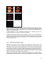
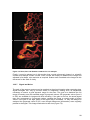
Figure 71: Optical sections with a variety of pinhole diameters (63x/1.4 objective). Pinhole
diameters from top left to bottom right: 4 AE; 2 AE; 1 AE; 0.5 AE; 0.25 AE. The strong loss of
light can be seen clearly with the small diameters, as can the pronounced background in the
images with very large diameters.
A pinhole diameter of 1 Airy is therefore the default setting. Switching objectives also
automatically adjusts the diameter of the pinhole accordingly.
A larger pinhole may be selected simply by adjusting a slider on the user interface for
specimens with weak fluorescence or high sensitivity against exposure to light. Of course,
smaller pinhole diameters may also be selected for very bright specimens. With reflecting
specimens in particular, the pinhole may be reduced to 0.2 or even 0.1 Airy units (AU) for the
thinnest possible sections.
10.2.6
Image Detail and Raster Settings
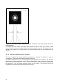
Depending on the objective used, conventional microscopes show a circular cutout of the
specimen. The diameter of the circle, multiplied by the magnification of the objective, is the
field number (FOV). The field number is therefore a microscope value which is independent
of the objective, and which, by reversing the operation, can be used to calculate the size of
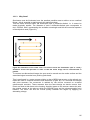
the specimen being observed. A scanner always acquires square or rectangular excerpts, of
course. If such a square or rectangle is exactly circumscribed by the field of vision, than the
diagonal dimension will correspond exactly to the field number, allowing the largest possible
image to be displayed on the monitor without restrictions.
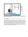
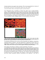
Unlike eyes or conventional cameras, scanners can simply be set to a smaller angle. A
further-enlarged section of the field of view will then be displayed on the monitor. It is thus
possible to zoom into details without the need for additional optics. As the scan angle can be
95