1
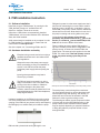
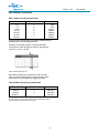
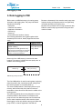
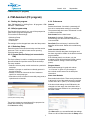
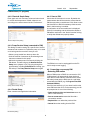
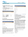
Issued: 3/12
Supersedes:
Pump Integrated Memory - PIM 01
Installation and user manual
This manual is applicable to the following versions:
Hardware: Software: PIM 01 (part no. 40-501551 and 40-501586)
PIM firmware v.1.14 (63 A, part no. 40-501551), v 2.00 (200 A, part no. 40-501586).
PC program v.1.1 - "PIM Assistant"©
1
Issued: 3/12
Contents
1.
2.
Introduction ................................................. 3
1.1. Product Documentation .............................. 3
1.2. Safety Regulations for Owner/Operator ..... 3
1.3. Guarantee ..................................................... 3
1.4. Symbols Used .............................................. 3
PIM installation instruction ......................... 4
2.1. Software installation ........................................ 4
2.2. Hardware installation and safety ..................... 4,5
3.
Data logging in PIM...................................... 6
4.
PIM Assistant (PC program) ....................... 7
4.1. Starting the program .......................................
4.2. Initial program setup .......................................
4.2.1. Workshop Setup ...........................................
4.2.2. General Service Setup .................................
4.2.3. Preferences ..................................................
4.3. Connecting a PIM to the PC ........................
4.4. Connecting an empty PIM
- New PIM routine ......................
4.4.1. Pump Setup ..................................................
4.4.2. Events & Graph Setup .................................
4.4.3. Pump Service Setup ....................................
4.4.4. Rental Setup .................................................
4.4.5. Save to PIM ..................................................
4.5. Connecting a non-empty PIM
- Returning PIM routine .............
4.5.1. Quick Overview ............................................
4.5.2. Service Reporting .........................................
4.5.3. Rental Setup .................................................
4.5.4. Save to PIM ..................................................
4.5.5. Optional Pump Setup ...................................
4.6. Analyzing Data .............................................
4.6.1. Trend Graph .................................................
4.6.2. Quick Overview ............................................
4.6.3. Service Log ..................................................
4.6.4. Alarm Log .....................................................
4.7. Loading a file - View data offline .................
4.8. Upgrading firmware .....................................
4.9. Restoring a PIM from file ............................
4.10. Resetting PIM to factory settings .............
4.11. Viewing software versions ........................
7
7
7
7
7
8
8
8
9
9
9
9
9
10
10
11
11
11
11
12
13
13
13
13
13
13
13
13
5.Appendices................................................... 14
5.1. Appendix 1 - File structure .......................... 14
2
Supersedes:
Issued: 3/12
1. Introduction
The Flygt Pump Integrated Memory (PIM) is a small
device for logging runtime, number of starts, pump
current and temperature inside the pump top. It also
stores administrative data such as data plate information,
customer information, application information and
service history. PIM data is administrated by means of a
PC program: “PIM Assistant”.
1.1. Product Documentation
Documentation delivered with PIM 01. Please check
that this manual version is applicable to the delivered
hardware and software versions (see cover inlet).
1.2. Safety Regulations for Owner/Operator
• All government regulations, local health and safety
codes shall be complied with.
• All danger due to electricity must be avoided.
1.3. Guarantee
• Modifications or changes to the unit/installation
should only be carried out after consulting with
Xylem Inc.
• Original spare parts and accessories authorized by
the manufacturer are essential for compliance. The
use of other parts can invalidate any claims for
warranty or compensation.
1.4. Symbols Used
Safety instruction
Personal safety - dangerous voltage
Special attention value
Apparatus or component damage
3
Supersedes:
Issued: 3/12
Supersedes:
PIM installation instructions
2. PIM installation instruction
2.1. Software installation
PIM gets its power from the same transformer that is
also used for measuring the current. PIM is rated for
6-63 Aac (part no 40-501551) or 60-200 Aac (part no
40-501586). The primary current must be maintained
above 6/60 A at all times. Note that this is true also if
the pump is starting and running without any load.
Install the program “PIM Assistant” by running the file
“PIM_Assistant_Setup.exe” available from the
Xylem Inc. Intranet. Follow the on-screen
instructions. USB drivers are automatically installed.
“PIM Assistant” will run under Windows XP or Windows
Vista, with JAVA installed.
Consequentially the primary current should
preferably stay between 40 and 60 Aac (part no 40501551) or 120-200 Aac (part no 40-501586) at full
load and the closer to 60/200 A the better.
JAVA must already be installed on the computer in order
for “PIM Assistant” to install and run. Down load and
install JAVA from www.java.com.
See also: chapter 4.3. “Connecting a PIM to the PC”.
2.2. Hardware installation and safety
Electrical wiring must be carried out only by a
qualified electrician and in accordance with
local regulations.
There is a delay at start-up before PIM begins to
log data. The delay varies with the magnitude of the
primary current, as shown for the 63 A PIM in the
graph below. The same principle applies for the 200
A PIM. This means that if the total primary current
is low, very short running cycles may not be
logged.
Always disconnect the pump power supply
before proceeding to carry out installation or
service on the PIM unit inside the pump.
Isolate the power supply before opening the
pump.
Ignoring these precautions may lead to
severe injury or death!
The PIM unit must be secured (e.g. with a
strap) to eliminate the risk of the phase lead
coming loose due to shakes or vibrations.
To prevent damage to the phase lead
isolation, make sure that the phase lead is not
squeezed between the PIM unit and adjacent,
sharp edged surfaces.
Hardware installation of the PIM unit is done by running
one of the phase leads one or several laps through the
opening in the PIM unit (see picture below) and strapping
the PIM tightly to a suitable fixed point inside the pump
top.
PIM unit with a phase lead running through it once.
4
Start-up time for a 63 A PIM depending on the total primary current.
The total primary current through the transformer
can be regulated simply by running the phase lead
several laps through the opening. The number of
phase lead runs must also be entered in the PIM
software in order to get the scaling correct.
The following two tables give the proposed number
of phase lead runs through PIM depending on the
pump’s rated current. Deviations from the tables
may be required depending on physical limitations
to fitting the cable the proposed number of runs
through the PIM.
Issued: 3/12
PIM installation instructions
Table 1 PIM 6–63 A (part no 40-501551)
Rated current # Phase lead runs Total current
6 A 7 42 A
7 A 6 42 A
8-9 A 5 40-45 A
10-15 A 4 40-60 A
16-20 A 3 48-60 A
21-30 A 2 42-60 A
30-63 A 1 30-63 A
Proposed number of phase lead runs through 63 A PIM depending on
the rated pump current; Resulting total current.
Example: If the pump is rated 17.5 A the phase lead
should be run 3 laps through the PIM unit, giving a total
current of 17.5 x 3 = 52.5 A.
PIM unit with 3 phase lead runs.
Note! When a PIM unit is connected to a PC via USB
cable, it will automatically enter “communication mode”,
during which it is prevented from logging any data.
Table 2 PIM 60–200 A (part no 40-501586)
Rated current # Phase lead runs 60-64 A 65-99 A 100-200 A 3 2 1 Total current
180-195 A
130-198 A
100-200 A
Proposed number of phase lead runs through 200 A PIM depending on
the rated pump current; Resulting total current.
5
Supersedes:
Issued: 3/12
Supersedes:
Data logging in PIM
3. Data logging in PIM
PIM contains a 4 MB flash memory for storing pump
information and logging data. The pump information
includes the following:
Because a timestamp is also stored at each pump start,
frequent starting and stopping results in a significantly
increased demand on the log memory.
• Data plate
• Customer information
• Application information
• Service log
• Alarm log
• Total runtime and number of starts
Because of the potential risk of losing operational data,
PIM also continuously logs the total running time and
number of starts.
The following parameters are logged together with a
timestamp from a built-in, battery supported real-time
clock:
Parameter
Logging interval
Pump current
Current variation
Temperature in PIM (junction box)*
Every 10th second
Every 10th second
Every minute
*Note that since the temperature is measured
inside the PIM unit this only gives a general
indication of the pump temperature.
Almost all of the 4 MB memory is reserved for data
logging. The memory is divided into two equal parts, as
shown in the following picture.
2 MB data log
2 MB cyclic data log
PIM data log memory allocation.
The first 2 MB partition is used for storing data, beginning
when the pump is first commissioned and ending when
this memory partition is completely filled up.
The second 2 MB partition is then employed as a cyclic
memory, which means that if any data is lost due to
extended run time, this will be data from the middle of the
running period.
The reasoning behind this memory disposition is that it
shall be possible to follow trends, for example in the
pump current, from when the pump was commissioned
and to make comparisons after some months of wear.
Data logging occurs only while the pump runs. When the
pump is idle, no data is registered in the PIM unit.
6
Issued: 3/12
Supersedes:
PIM Assistant (PC program)
4. PIM Assistant (PC program)
4.1. Starting the program
4.2.3. Preferences
Start “PIM Assistant” by clicking Start – All programs – PIM
Assistant – PIM Assistant.
General
4.2. Initial program setup
The first time the program is run, you will be prompted to
make a basic program configuration.
This consists of three dialogs:
Password activated: if checked, a password will
have to be entered when setting up a new PIM.
The password will then have to be entered in order
to read from the PIM.
Date format: Select a date format.
• Workshop Setup
• Service Setup
• Preferences
Auto save: If checked, “PIM Assistant” will
automatically save the files down loaded from a
connected PIM.
The settings can be changed later under the Setup menu.
Save Path: Enter a directory in which the PIM
data files will be saved. Default is the subdirectory
’PIMs’.
4.2.1. Workshop Setup
Enter the names of the service workshop and the service
personnel. This is an aid for faster service reporting.
Click Next when ready.
4.2.2. General Service Setup (not connected to PIM)
The Service Setup is used for creating general templates
that will facilitate and optimize service at the workshop.
The setup enables:
• Selection of those pump models serviced at a particular workshop.
• Addition of pumps or machines not already present in the drop-down list.
• Addition or removal of items in the list of measures specific for each pump type.
• Association of time counters for essential pump parts, to optimize service intervals.
Quick Overview Defaults
Select this if the full data plate, the diagram and
the alarm log shall be visible on the Quick overview
page as default.
If the full data plate is not chosen, only the
mandatory fields will be displayed (Serial number,
Product number, Voltage, Current and Input
power).
Diagram Default
Enter default settings for graph axis values.
“% of Current” is given as a percentage of
the nominal current entered in the data plate
information.
Alarm Level Defaults
Enter default alarm limits. These are by default set
to 85% and 110% of the rated current for low/high
current and to 85 °C (185 °F) for the temperature.
If the alarm level settings for the PIM need to be
changed at a later stage, the alarm limits will be
entered in Amperes instead of as a percentage of
the rated current.
(General) Service Setup dialog
The service measures entered here will be proposed as
default when setting up a new PIM unit.
Click Next when ready.
Preferences dialog
Click Save when you are satisfied with the settings.
These can all be edited later under the Setup menu.
7
Issued: 3/12
Supersedes:
PIM Assistant (PC program)
4.3. Connecting a PIM to the PC
4.4. Connecting an empty PIM
Install the software (“PIM Assistant”) before connecting
a PIM unit for the first time! This ensures that the USB
drivers are in place before connecting any hardware.
Connect a USB cable between the PIM and your
computer. The PIM connects to a type B connector, so
you will typically need a type A to type B cable.
• Pump Setup
• Event & Graph Setup
• Service Setup
• Rental Setup
• Save to PIM
- New PIM routine
When an empty PIM unit is connected, PIM Assistant
starts the “New PIM routine”, consisting of five steps:
4.4.1. Pump Setup
Enter pump PIM ID, Number of phase lead runs
through PIM (see chapter 2, “PIM installation
instruction”), Pump data plate information and
Password (if activated). Mandatory fields are shown
in red until properly filled in.
USB connectors of the types A and B
The PIM ID is used for naming files and save folder
and has to be unique. Note! If the PIM ID already
exists, the field will be shown in red. This problem is
solved by either re-naming the new PIM or by moving/
deleting the directory named after the present PIM ID
in the PIM files directory (default subdirectory PIMs).
Number of phase lead runs through PIM is an
important parameter that will affect the scaling of the
logged current, as previously discussed. Make sure
that the number entered corresponds to the actual
physical number of phase lead runs (see chapter 2,
“PIM installation instruction”)!
“PIM Assistant” will automatically detect the connected
PIM unit. When a PIM is connected to a PC with “PIM
Assistant” the PIM internal clock will be automatically
synchronized to the computer clock.
The first time a PIM is connected to the computer,
Windows will detect it and install software.
USB drivers are automatically installed with the “PIM
Assistant” software. When prompted for the “USB Serial
converter”, select to “Install the software automatically”.
Windows will then search for and install the appropriate
drivers, which may take several minutes. Be patient; If
you interrupt this process, the setup will fail!
These settings can be edited later by selecting
Optional pump setup on the orange work flow bar
when PIM is connected.
This procedure is repeated for the “USB Serial port”.
Changes made in “PIM Assistant” are only written to the
PIM when the Save button is clicked. No automatic data
synchronization is performed, so remember to Save
before exiting!
The PIM unit is powered from the USB port while it is
connected to a PC.
Tip! In order to verify proper installation of a PIM unit,
begin by starting “PIM Assistant”, then connect the PIM
unit to the PC. The message “PIM device connected...”
should now appear right under the menu bar in the
“PIM Assistant” program. (Windows notification in the
lower right corner is only displayed once, the first time a
PIM is connected to the USB port.)
Pump Setup dialog
8
Issued: 3/12
Supersedes:
PIM Assistant (PC program)
4.4.2. Events & Graph Setup
4.4.5. Save to PIM
Enter graph axis min. and max. values and alarm levels
for current and temperature. Default values are set
according to the values entered under “Preferences”
Check that all information is correct. By default old
measurement data will be erased to ensure that the
PIM is empty when commissioned. Click Save to save
the information to PIM. All mandatory fields must be
filled in before saving is enabled.
A confirmation of the successful save is displayed.
Click OK in the dialog and the information written to
PIM will be read back in the “Quick Overview” dialog
to verify that all data was properly written.
Events & Graph Setup dialog
4.4.3. Pump Service Setup (connected to PIM)
This dialog is used for setting up a specific list of service
measures and counters for a particular pump, to be used
on recurring service occasions. Here you can:
• Select a pump model from the drop-down list.
• Limit the total list of measures by de-selecting those
that are not wanted for this pump.
Quick Overview dialog.
• Add service measures and counters by clicking the
Edit button. This will bring up the General Service
Setup menu (chapter 4.2.2.). By going through the
general setup, including Preferences and saving, you
will end up in the Pump Service Setup menu again.
The PIM unit can now be unplugged from the PC
and is ready to start logging.
4.5. Connecting a non-empty PIM
- Returning PIM routine
When a PIM that has a PIM ID is connected to a PC,
“PIM Assistant” will automatically down load and
save data from the PIM unit. Data files will be saved
with today’s date and the PIM name in a sub folder
named after the PIM ID (e.g. C:\Program Files\PIM
Assistant\PIM123).
(Pump) Service Setup dialog
If the file name exists (e.g. if you down load from the
same PIM more than once on the same day) you will
be prompted to do one of the following:
4.4.4. Rental Setup
Enter customer and application information.
• Open another archive and save there saves the files in a new directory.
• Save as a new version saves the files with a
consecutive number.
• Replace files over writes the previous files.
• Cancel aborts the reading from the PIM.
Rental Setup dialog
9
Issued: 3/12
Supersedes:
PIM Assistant (PC program)
The “Returning PIM routine” consists of four main steps:
• Quick Overview
• Service Reporting
• Rental Setup
• Save to PIM
In addition to these four steps, it is also possible to study
the logged data in graphs, to view the service log
(see chapter 4.6, “Analyzing data”) and to edit the data
plate and number of phase lead laps (see chapter 4.5.5,
“Optional pump setup”)
4.5.1. Quick Overview
When a returning PIM is connected, a Quick overview
page will display the following data:
• General pump information: PIM ID, Customer,
Application and Location
Quick Overview dialog
• Pump data plate: Data plate information
To view larger graphs and see service history, click the
diagram or menu Analyze – Open trend diagram (See
chapter 4.6, “Analyzing data”).
• Custom data plate: Possible extra data plate
information
• Running info:
• Logging started. Time of first logged value in
data base
• Logging ended: Time of last logged value in data base
• Date of latest service
• Runtime and number of start since latest service
• Total runtime and number of starts (since PIM
was installed)
• Current and temperature min. and max. values
during this logging period
• Percentage of runtime above/below alarm limits
• Alarm log
Longer texts that may not be displayed in full, will be
expanded at mouse-over.
The serial and product numbers can be copied to the
clipboard by left-clicking on them. This allows for easy
pasting into the Flygt service guide, for example.
The data plate, alarm log, and diagram box can be
minimized by clicking the “[-]” symbol. The minimized
data plate shows only the mandatory entries (Serial
number, Product number, Voltage, Current and Input
power).
4.5.2. Service Reporting
This section allows for easy service reporting. Click
Service & reporting on the orange work flow bar to
enter the service reporting dialog.
1. Choose service person from the drop-down list. If
the intended person is missing from the list, click the
menu Setup – Workshop setup and enter a new
name.
• Diagram thumbnail (click to enlarge graph, view other
graphs and view service log)
2. Enter free text service notes.
3. Check in the Select column the service measures
that have been (or will be) carried out.
Entering what service measures are carried out (i.e.
which parts are replaced) on each service occasion,
facilitates following the service history of the pump.
Note that the black bar in the Counter field gives a
graphical indication of the service interval status for
the component: e.g. the Main bearing counter in the
example image below has reached 40% of its service
interval.
10
Issued: 3/12
Supersedes:
PIM Assistant (PC program)
To add a service measure to the list:
1. Click Setup – Service on the black menu bar, then Add Measure. Step through the entire Setup flow and Save.
2. Click Optional Setup on the orange work flow bar and check the service measure.
3. Return to Service & reporting to report the new
service measure.
Save to PIM dialog
4.5.5. Optional Pump Setup
Click Optional pump setup on the orange work flow
bar to edit the data plate information, PIM ID or the
number of phase lead runs through PIM. Don’t forget
to go back to Save to PIM and click Save in order to
save the setting to the PIM unit.
Service Reporting dialog
4.5.3. Rental Setup
Edit the contents only if any information has changed.
If the pump is returning to the same customer and the
same site there is no need to change anything here.
4.6. Analyzing Data
Rental Setup dialog
Note that loading data while in the “Returning PIM
routine” (i.e. having a PIM connected) will abort this
routine. It is then possible to reconnect that PIM unit
to restart the “Returning PIM routine” and make a
service report.
When a returning PIM has been connected or when a
previously stored data file is loaded (File – Open file)
the Quick overview page is displayed. By clicking the
diagram thumbnail or selecting the menu Analyze
– Open trend diagram, a new window is opened.
In this window it is possible to display logged data
in different graphs and to view the Quick Overview,
Service Log and Alarm Log.
It is possible to go back to the main window and load
a new file; Select Analyze and view data from two
different files in two different windows at the same
time.
4.5.4. Save to PIM
Make sure that all settings are correct and decide if the
previously logged data should be erased. The default
setting is to Clear old measurement data from PIM
since the data is now already saved on the PC. It is
also generally wise to free up the PIM resources to
extend the logging capacity (see chapter 3, “Data
logging in PIM” ).
The Analyze window consists of four steps:
• Trend Graph
• Quick Overview
• Service Log
Note that no data is written to PIM until the Save button
is clicked.
• Alarm Log
11
Issued: 3/12
Supersedes:
PIM Assistant (PC program)
4.6.1. Trend Graph
Alarm Setup - Set, show or hide alarm limits.
Right-click the alarm names to change the
colours of alarm lines and fields.
Display Setup - Choose which channels/graphs to
view. All graphs are displayed in the same window,
although some graphs are more combinable than
others. Right-click the different channels to change the
graph colors.
The checkbox determines whether to show the
alarm limit in the graph or not.
Apply to Graph: changes the displayed alarm
limits in the graph.
• Current: Displays current, logged every 10th second.
Update Alarm Log: recalculates the alarm log
with the new alarm limits. It also recalculates the
percentage of time the pump has been running
over and under the alarm limits, which is shown
on the Quick Overview.
• Show edges: If checked, the current graph will show
the edges going from and to zero. This makes it
easier to view data when zoomed in.
• Variation: Displays the current variation –
a parameter indicating how much the current is varying, logged every 10th second. A high variation could indicate snoring, unbalanced impeller or some other unfavourable running condition.
Restore: restores the last saved axis and alarm
limit settings.
Zooming
To zoom in, hold down the left mouse button and
draw a box over the area of interest. The box has
to be drawn from top left to bottom right. Release
the left mouse button to zoom in.
• Temperature: Displays the PIM temperature, logged
every minute. This is the internal temperature in the
PIM unit which is placed in the pump top, giving a
general indication of the pump temperature.
• Starts per hour: Displays how many times the pump
has started each hour. This gives a snapshot of how
regularly the pump is running.
• % Running: Displays the percentage running per 24
hours. 100 % means continuous running.
• Pump duty graph: Displays the runtime as a colour
coded schedule. Gives a snapshot of how much the
pump is running over or under the alarm limits.
Zoom in by drawing a rectangle
To go back one step at the time, simply left-click
on the graph.
Trend Graph window
Axis Setup - Enter the max. and min. values for the
different graph axis.
Import Graph Axis Values: sets the values to the present
values in the graph.
Save Axis: saves the axis values to PIM/file.
Apply: applies the set limits to the graph.
12
To zoom out all the way, hold down the left
mouse button and draw a short line to the left.
When releasing the button, the graph will zoom
out to show all available data.
Issued: 3/12
Supersedes:
PIM Assistant (PC program)
4.8. Upgrading firmware
When a PIM is connected, select menu PIM
– Upgrade FIRMWARE and choose a PIM
firmware file (.hex).
Make sure that the PIM unit is not
disconnected during the upgrade, or
corruption in the data transfer might
render it unusable!
4.9. Restoring a PIM from file
It is possible to make a “copy” of a PIM unit (e.g. if
it is broken or missing). Select menu PIM – Restore
from file and choose a pump-info file (.pmp) to
restore from.
Zooming out all the way
Saving and printing a graph
Right-clicking the graph brings up a menu for saving the
graph as a PNG image or sending it directly to a printer.
4.6.2. Quick Overview
To replace a broken or missing PIM, it is
recommended to restore from the latest available
pump-info file. The PIM will now be loaded with the
settings from the selected file (Total runtime, number
of starts, service log, data plate, alarm limits, etc.).
Note that data bases will not be written back to a
PIM.
See chapter 4.5.1, Quick Overview.
4.6.3. Service Log
4.10. Resetting PIM to factory settings
This displays the service log where previous service
occasions are recorded.
To reset a PIM unit to factory settings, do the
following:
1. Connect the PIM unit to the PC.
2. Wait until “PIM Assistant” has read all information
from the PIM unit.
3. Select menu PIM – Reset PIM to factory settings
4. Disconnect and reconnect the PIM unit to enter the
new PIM routine.
Note that all measurement data, log files and
information stored in the PIM will be deleted.
Service Log dialog
4.11. Viewing software versions
Menu Help – About will display the current software
version of the “PIM Assistant” and, if a PIM is
connected, the current firmware version of the PIM
unit as well.
4.6.4. Alarm Log
This displays the alarm log.
4.7. Loading a file - View data off-line
To view data when a PIM is not connected to the
computer, select menu File – Open file. Choose a file
(.pmp) and click Open.
13
Issued: 3/12
Supersedes:
Appendices
5. Appendices
5.1. Appendix 1 - File structure
By default the save path of the “PIM Assistant” is “C:\Program Files\PIM Assistant\PIMs”.
The save path may be edited under menu Setup – Preferences.
When a new PIM is set up, a folder is created with the same name as the PIM ID, e.g.
“C:\Program Files\PIM Assistant\PIMs\PIM123” if the PIM is named “PIM123”.
In this folder all files associated with this PIM ID will be saved by default.
Files are named with the date they where created, the PIM ID and the type of the file, e.g.
“080131_PIM123_Pumpinfo.pmp”.
The PIM data is divided into five different file types:
• <date>_<PIM name>_Datalog.dta contains the data log. Current, current variation and temperature with time
stamps.
• <date>_<PIM name>_Parameters.par contains PIM internal parameters. Changing these may cause the PIM to
not function properly!
• <date>_<PIM name>_Pumpinfo.pmp contains configuration settings (PIM name, address, customer, application, alarm limits), data plate info, service log and counters.
• <date>_<PIM name>_Eventlog.evt contains the event log.
• <date>_<PIM name>_Alarmlog.alr contains the alarm log.
These five files are created when a returning PIM has been connected.
After doing a service routine and saving to PIM, two special files are created:
• <date>_Out_<PIM name>_Parameters.par
• <date>_Out_<PIM name>_Pumpinfo.pmp
These files contain the most recent changes to service log, customer information, application information and so on,
but do not have any associated data log, event log or alarm log.
If a filename already exist when reading from a PIM (e.g. if the same PIM unit is connected more than once on the
same day) and the option Save as a new version is chosen, the file names will acquire a consecutive number and
have the following format:
• <date>_1_<PIM name>_Pumpinfo.pmp
14