1
R
Version 03
USER S MANUAL
PARTS BOOK
FORTUNA
AC Servo Motor series
lity
a
u
tQ
Besst Pricevice
Be st Ser
Be
1. Thank you for purchasing our product. Based on the rich expertise and
experience accumulated in industrial sewing machine production, SUNSTAR
will manufacture industrial sewing machines, which deliver more diverse
functions, high performance, powerful operation, enhanced durability, and
more sophisticated design to meet a number of user’s needs.
2. Please read this user’s manual thoroughly before using the machine. Make
sure to properly use the machine to enjoy its full performance.
3. The specifications of the machine are subject to change, aimed to enhance
product performance, without prior notice.
4. This product is designed, manufactured, and sold as an industrial sewing
machine. It should not be used for other than industrial purpose.
R
USER S
MANUAL
1. SAFETY INSTRUCTION ............................................................................................... 8
2. PRECAUTIONS BEFORE USE .................................................................................. 10
3. LOCATING AND USING PARTS OF THE CONTROLLER BOX .............................. 12
4. INSTALLATION ............................................................................................................ 14
1) Attaching controller to table .................................................................................... 14
2) Attaching pedal unit ................................................................................................ 14
3) Installing and adjusting knee lifter solenoid ............................................................ 15
4) Needle Bar Up/Down Stop Position Setting ........................................................... 15
5) Installing program unit ............................................................................................. 18
6) SunStar machine installed with program unit ......................................................... 18
5. WIRING AND GROUNDING ....................................................................................... 19
1) Specification of the power plug ............................................................................... 19
2) Specification of electric current in wiring of power plug ......................................... 19
3) Names and Explanation of external connector in control box ............................... 20
4) Changing solenoid supply voltage (Basic setting values upon shipment: J19) .... 20
6. CONNECTION THE EARTH WIRE OF THE SEWING MACHINE AND MOTOR ...... 22
7. THINGS TO BE CHECKED AFTER INSTALLATION ................................................ 22
8. PROGRAM UNIT PART NAMES AND METHOD OF USE ....................................... 23
1) Program unit part names ........................................................................................ 23
2) Program Unit Method of Use .................................................................................. 23
3) Start and End Backtack Stitch Correction Method ................................................. 34
4) Method of Use: Inertia Tuning Function ................................................................. 37
5) Sewing machine head open error and safety switch error .................................... 37
6) How to Use Edge Sensor ....................................................................................... 38
7) Motor Controller Setting .......................................................................................... 41
8) Use of KM-360J ...................................................................................................... 45
9) Use of Detailed TPM(Total Production Maintenance) Functions............................ 46
9. SIMPLE OPERATION UNIT PART NAMES AND METHOD OF USE ...................... 49
1) Names of Each Part in the Simple Operation Unit ................................................. 49
2) Simple Program Unit Method of Use ...................................................................... 49
10. FORTUNA SERIES 4 FULL FUNCTION SOFTWARE METHOD OF USE ............ 54
1) Basic Functions of the Fortuna Series 4 Full Function Software ........................... 54
2) Fortuna Series 4 Full Function Software Specific Parameters .............................. 55
3) Method of Use and Explanations for Specific Items of the Parameter .................. 69
4) Thread Trimming Sequence Function Method of Use
(Items no. 54, 55, 56 of Group B) ........................................................................... 73
11. BREAKDOWN AND TROUBLESHOOTING ............................................................ 82
12. HOW TO PLACE FOR CONTROLLER .................................................................... 83
13. BLOCK DIAGRAM ..................................................................................................... 84
Fortuna IV 750W USER’S MANUAL .......................................................................... 85
(What is not specified here can be found in “User Manual for Fortuna Series 4”.)
1. PRECAUTIONS BEFORE USE .................................................................................. 86
2. LOCATING AND USING PARTS OF THE CONTROLLER BOX .............................. 88
3. INSTALLATION ............................................................................................................ 90
1) Mounting your Servo Motor on the table...................................................................90
2) Assembling the belt cover and adjusting the belt tension.........................................91
3) Attaching controller to table .......................................................................................92
4) Attaching pedal unit ...................................................................................................92
5) Installation of full function program unit.....................................................................93
6) Small-type Program Unit Installation Method ...........................................................94
7) SunStar machine installed with program unit............................................................94
8) Mounting and adjusting the foot-lift solenoid.............................................................95
9) Mounting the position sensor (Synchronizer) and setting the film............................96
10) How to equip and adjust a built-in location detector(synchronizer)........................98
4. WIRING AND GROUNDING ...................................................................................... 100
1) Specification of the power plug................................................................................100
2) Specification of electric current in wiring of power plug ..........................................100
3) Names and Explanation of external connector in control box ................................101
4) Changing solenoid supply voltage (Basic setting values upon shipment: J19) .....102
5. CONNECTION THE EARTH WIRE OF THE SEWING MACHINE AND MOTOR ......... 103
6. THINGS TO BE CHECKED AFTER INSTALLATION .............................................. 103
7. PARTS NAME AND USE OF SMALL-TYPE PROGRAM OPERATING PANEL .... 104
1) Parts Name of Small-type Program Operating Panel ......................................... 104
2) Use of Small-type Program Operating Panel ....................................................... 105
3) Use method of product counter and bobbin counter............................................. 110
4) Using Method of the Short Thread Trimmer Type ................................................ 114
5) Initial and Close Backtack Accuracy Function Correction Method ...................... 116
6) Small-type Program Operating Panel Functions Same as Full Function Program
Operating Panel ..................................................................................................... 117
8. Fortuna Series 4 750[W] Full Function Software Method of Use ...............................118
1) Basic Functions of the Fortuna Series 4 750[W] Full Function Software ...............118
2) Fortuna Series 4 750[W] Full Function Software Specific Parameters ..................119
PARTS BOOK ........................................................................................................... 134
Be sure to read and keep in mind the following instructions before you install and use
the FORTUNA SERVO MOTOR.
1) Use and Purpose
This product is designed, manufactured, and sold as an industrial sewing machine. It should not be used for
other than industrial purpose.
2) Working Environment
Power Source
It is desirable that voltage of the power source be kept within the range of 10% of the rated voltage.
It is desirable that frequency of the power source be kept within the rage of 10% of the rated frequency.
(50/60 )
The SERVO MOTOR can be expected to work normaly only in case the foregoing things are kept.
Electromagnetic Noise
It is desirable that those equipments causing strong electromagnetic field or high frequency not use the
same electrical outlet as this on and stay away from it.
Temperature and Humidity
Keep the ambient temperature above 5 degrees and below 40 degrees Centigrade.
Never use it outdoors and avoid direct ray of light.
Keep it away from an hot object like a stove.
Keep the ambient humidity above 30% and below 95%.
Never use it near gases and explosives.
Do not use it at a spot located 1,000m or higer above sea-level.
Keep the storage temperature higher than 25 degrees below zero and lower than 55 degrees Centigrade when
not in use.
3) Installation
Follow the instruction carefully when installing it.
Be sure to start installing it after pulling the power plug off the outlet.
Fix the cable so that it may not move, and do not allow the moving parts like belts to be interfered with.(Keep
distance of at least 25mm from them.)
Be sure to have the Controller and the sewing Machine grounded.
Be sure that the voltage of power source fits the specification of the Controller before the power is on.
Be sure to use Safety Extra Low Voltage when an extra item or an accessory is fitted into the Controller.
4) Disassembly
Indisassembling it, be sure to wait at least 360 seconds before taking any action after pulling the plug off the
power source after turning it off.
When pulling off the plug from the power source, be sure to hole the plug itself instead of the wire connected
to the plug.
8
5) Service and Maintenance
Make sure that service and maintenance are carried out by a skilled technician.
Never try to operate with the Motor and the Controller open.
When inserting a thread into or touching the machine, be sure to turn the power off and step down from the
platform.
Be sure to use standard products specified for replacement of parts.
6) Other Safety Instructions
Tack care not to let your fingers touch any moving parts including belts.
In case of remodelling or fitting of additional device, be sure to follow safety standards and do not ever try to
go ahead based on your own judgments.
Do not try to operate with the safety device removed.
Take care not to let water or coffee or something like those admitted into the Controller or the Motor.
Never drop the Controller or the Motor to the ground.
The instructions presented above are for the safer and more proper operation of the Fortuna Servo
Motor. Ignoring such instructions could cause damage to the machine or physical injury of the user.
Please follow all the instructions when operating the machine.
9
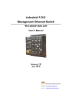
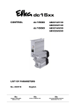
1. Do not turn on the power while stepping on the pedal.
2. Turn off the power when leaving the servomotor overnight.
3. Turn off the power when servicing the servomotor or changing
the needle.
4. Be sure to keep the servomotor securely grouned.
5. Do not connect multiple servomotor power plugs to the same
power strip.
6. Install the servomotor away from noise sources, such as highfrequency equipments and welding machines.
7. Avoid electrical shock when servicing the controller box. (Wait for 6
minutes before opening the cover after turning off the power.)
8. When an error message Er sppears on the digital display,
take a note of the Er code, and then turn on and off before
resuming operation(Contact the local dealer if Er message
persists on the display)
10
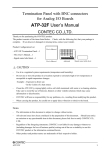
9. Clean it every two or three weeks so that no dirt or a dirty
substance may be piled up.
10. When replacing the fuse, use a standard item, opening the
cover as shown in the diagram.
11. Make the length of the cable connected with an outside parts
like stand-up pedal as short as possible.
11
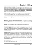
1) Front and back of control box
Control box front (Full Option Type)
Control box back (Full Option Type)
Control box grounding part
AC Power Input Power Cable
Option 2 Connector
Pedal Connector
AC Power switch
Encoder Connector
Motor Power Connector
P/U Connector
Position Detector Connector
Option 1 Connector
Lamp Power Connector
A/B Button Connector
Solenoids Connector
Option 3
Control box front (Economic Type)
Control box back (Economic Type)
Control box grounding part
AC Power Input Power Cable
Option 2 Connector
Option2
Pedal Connector
AC Power switch
Pedal
Encoder Connector
Motor
Encoder
Motor Power Connector
P/U
Synchro
P/U Connector
Option1
Simple Controller Board
Position Detector Connector
Button
A/B
Option 1 Connector
Lamp Power Connector
S/M
A/B Button Connector
Solenoids Connector
SUNSTAR ELECTRIC CO., LTD.
12
2) Control box side
Caution
Specification
13
1) Attaching controller to table
As in the figure, attach control box to the lower right of the table with 15mm fixing screws.
The underside of the table, front part
Right table leg
Area where control box is
to be attached
2) Attaching pedal unit
As in the figure, attach pedal unit bracket to the underside of table with 15mm fixing screws.
Attach pedal unit to the fixing holes on one side of pedal unit bracket.
Pedal unit bracket should be fixed to the area where the bar linked to the pedal that is to be attached to table leg becomes vertical.
(The area where pedal unit bracket is attached depends on where the pedal is.)
14
3) Installing and adjusting knee lifter solenoid
(1) For Sunstar KM-2300 Sewing Machine
Assemble Ornamental panel of knee lifter solenoid on the back
of KM-2300 body
Attach knee lifter solenoid on bracket A.
Attach the bracket A fixed on the knee lifter solenoid.
After attaching crank on the solenoid shaft, connect to the
machine.
Put cover over solenoid.
Connect grounding cable.
Solenoid bracket A
Presser foot Solenoid Cover
Grounding Cable
Solenoid Crank
Solenoid Cover
KM-2300 Back
4) Needle Bar Up/Down Stop Position Setting
(1) Installing Position detector (KM-2300Series, SC-7300Series)
Synchronizer is attached on the machine upon shipment.
When changing and fixing synchronizer, see the manual.
(2) Setting needle bar up-/down- stop position with using program unite (KM-2300Series, SC-7300Series)
- Fortuna Series IV allows a user set up-down stop position by using program unite without changing setting of synchronizer.
Setting needle bar up-down stop with using optional program unite.
Turn on the down-stop icon lamp by pressing needle bar up-/down-stop
button on the program unit to set needle bar down-stop position.
When the up stop lamp on, press needle bar up-down stop button
with pressing
the button. After that, as in the figure letter showing
information on the setting target and number pointing the current position
will blink.
Turn the pulley forward manually to move the needle bar to the desired
position. The screen displays changing position of needle bar.
When the needle bar moves to the desired position, save the position by
pressing
key. Then, the screen automatically returns to the initial screen
with a buzzer.
[Caution]
Returning to the initial screen by pressing
button without pressing
button will not save reset values.
15
Furthermore, turn on the down-stop icon lamp by pressing needle bar up/down-stop button on the program unit to set needle bar down-stop position.
When the down-stop lamp turns on, press
button while pressing needle
bar up-/down-stop button.
Then, as in the figure right, the information
on what is to be set and the numbers that tell the current position of needle
bar will be shown.
Turn the pulley forward manually to move the needle bar to the desired
position. The screen displays changing position of needle bar.
When the needle bar moves to the desired position, save the position by
pressing
key. Then, the screen automatically returns to the initial screen
with a buzzer.
[Caution]
Returning to the initial screen by pressing
button without pressing
button will not save reset values.
Setting needle bar up-/down-stop position by using simple controller board (front OP).
Turn on the up-stop icon lamp by pressing needle bar up-/down-stop button
on the simple controller board to set needle bar up-stop position.
When the up-stop lamp turns on, press “E” button while pressing needle bar
up-/down-stop button ( C ). Then, as in the figure right, the numbers that tell
the current position of needle bar will be displayed.
The operator turns the pulley forward manually to move the needle bar to the
desired position. The screen displays changing position of needle bar.
When the needle bar moves to the desired position, save the position by
pressing C key. Then, the screen automatically returns to the initial screen
with a buzzer.
[Caution]
Returning to the initial screen by pressing E button without pressing C button will not save reset values.
16
To set needle bar down stop position, press needle bar up-down stop button
of simple controller board to make on the icon lamp of needle bar up stop.
When the down stop lamp on, press needle bar up-down stop button C
with pressing E button. After that, number pointing the current needle bar
position will blink.
Turn the pulley forward manually to move the needle bar to the desired
position. The screen displays changing position of needle bar.
When the needle bar moves to the desired position, save the position by
pressing C key. Then, the screen automatically returns to the initial screen
with a buzzer.
[Caution]
Returning to the initial screen by pressing E button without pressing C button will not save reset values.
[Caution]
The names of buttons on simple controller board are as follows.
A Button switch( Switch for initial Reverse)
B Button switch (Switch for end reverse)
C Button switch (Switch for needle bar up-down stop when the machine
stops)
D Button switch (Switch for automatic presser foot ascending when the
machine stops)
E Button switch (Switch for program)
17
5) Installing program unit
As in the figure below, attach program unit bracket to program unit with three fixing screws. As in the figure, attach the bracket with
program unit to the head of machine firmly with two fixing screws.
6) SunStar machine installed with program unit
18
1) Specification of the power plug
(1) Single phase 100V~120V
(2) Single phase 200V~240V
(3) Three phase 200V~240V
Be sure to connect Protective Earth
2) Specification of electric current in wiring of power plug
Be sure to use wiring materials which can stand electric current of higher than 15A.
19
3) Names and Explanation of external connector in control box
Solenoid Connector (5566-16P)
Basic switch connector (5566-8P)
[ Pin Number ]
1, 9: Back Tack solenoid
2,10: knee lifter solenoid
3,11: Trimming solenoid
4,12: Wiper solenoid
[ Pin Number ]
5,13: Left needle control
solenoid
6,14: Right needle control
solenoid
7,15: Thread release solenoid
8,16: Auxiliary solenoid
Switch and lamp connector (5566-14P)
1,5: Manual Back tack
button
2,6: Back tack Insert/Delete
Button
Extension connector (5566-20P)
[ Pin Number ]
1, 2, 7 : GND
3
: Left switch LED
4
: Right switch LED
5
: Left switch
6
: Right switch
8
: VCC (5[V])
3,7: Knee lifter solenoid switch
4,8: Safety Switch
[ Pin Number ]
9 : 4/4
10 : 3/4
11 : 2/4
12 : 1/4
13 : Switch-HALF
14 : Switch-CNT
9, 10 : 12[V]
11 : Output 12
1~6 : GND
12 : Output 13
7, 8, 17~20 : VCC (5[V])
13 : Output 14
14 : Output 15
15 : External Input 00
4) Changing solenoid supply voltage (Basic setting values upon shipment: J19)
It is for a good operation of solenoid when AC input voltage changes.
Setting values of solenoid supply voltage against input voltage (input voltage 220V series)
Solenoid with the rating current of 30V
20
Solenoid with the rating current of 24V
Input Voltage
Setting Values
Input Voltage
Setting Values
Less than 210V
J20
Less than 180V
J20
210V~230V
J19
180V~190V
J19
More than 230V
J18
More than 190V
J18
Setting values of supplied voltage to solenoid against input voltage (Input voltage: 110V)
Solenoid with rating current of 30V
Solenoid with rating current of 24V
Input Voltage
Setting Values
Input Voltage
Setting Values
Less than 100V
J20
Less than 90V
J20
100V~120V
J19
90V~100V
J19
More than 120V
J18
More than 100V
J18
Setting supplied voltage
21
Method
As in the figure, connect grounding conductors (green or
green/yellow) that link the machine and the controller. Check if
grounding part of power is connected to the grounding conductors.
Caution
Failure to ground the motor can cause abnormal
operations, such as overspeed rotation or unwanted
stitching.
1) Before the power is on...
Make sure that the incoming voltage is in accordance with that shown in the name plate of the Control box.
Check whether the following connectors are connected.
Check to see the fixing nuts for pulley are tightly fastened.
Check whether the sewing machines are right kinds (Chain Stitch S/M, Lock Stitch S/M)
Check the rated voltage for Solenoid (Refer to How to change the electric voltage supplied for Solenoid ))
2) After the power is on...
Check whether the program unit is working.
Check the direction of rotation of the Sewing Machine.
In case the direction of rotation is not right, action shall be taken to change set it right, referring to the methods of changing the
program and the list of changing functions (N. 65 in Group A )
Check to see whether there are abnormal heat, smell or noise nearby.
In case there are, turn the power off and call our regional office.
22
1) Program unit part names
2-Digit Displayer
Start B/T Selection Button
Button to Select Presser Foot-lift
Location When Machine Stops
Sunstar Logo
End B/T Selection Button
Thread-trimmer and Wiper Selection
4-Digit Displayer
Button to Select Needle Plate Location When Machine Stops
1/2 Stitch Button
Pattern Work Selection Button
Button for Program Change
Button for Counter Use after Counter Programming
Button to Save Program Changes
Button to use Edge Sensor Selection after Edge Sensor Programming
Button to Change the Sewing Speed Installation
Constant Sewing Speed Selection Button
Pattern Work Connecting Button
2) Program Unit Method of Use
(1) 4-Digit Displayer and 2-Digit Displayer Functions and Method of Use
A. 4-Digit Displayer and 2-Digit Displayer Functions
<Initializing screen>
When you turn the power on, you will see a screen as shown in the figure.
The 4-digit displayer shows the start and end B/T sewing and the 2-digit
displayer shows the current abbreviation for the letters or numbers shown in
the 4-digit displayer (bt: the abbreviation for back tack),
<Example of error detection>
The 4-digit displayer shows the error number for each type of error
discovered and also shows the programmed value after it has been
programmed. The 2-digit displayer shows the number of the parameter
specific item's content or name which is shown in the 4-digit displayer.
<Example of selection of number 2 item in Group A>
[ Caution ]
The 4-digit displayer and 2-digit displayer show the current condition. Therefore the user should always check it before using the
machine.
23
B. Method of Use: 4-Digit Displayer and 2-Digit Displayer
a. Method to change the start and end B/T stitch numbers
In order to change the start B/T stitch numbers which is programmed when you
first purchase this machine, you must use the
,
buttons. If you want to
change the end B/T stitch numbers, you must use the
,
buttons.
The program range is from 0 to 9.
(Ex: How the screen looks when changing both start and end B/T stitch
numbers to 4).
b. Method to check or change the specifics of the parameter
Press the
button and as you press it, also press the
button. Then
you can either check or change the programming items for the parameter of
, B group
, C group
, D group
)
group A. (A group
Users should turn
the machine off to select B, C, or D group. While pressing the
button,
turn the power switch on. The screen will be changed to the initial screen
after showing the "PrEn" message. Then, the users can select B, C, or D
group by pressing B, C, or D button while holding program
button.
You can move to the parameter item you want with the
and
buttons. The parameter item number will appear in the 2-digit displayer and
the wanted value will appear in the 4-digit displayer.
(Ex) Screen showing the maximum speed limit preset in the item 2 of A group)
After using the
(increase) button and
the value you want, press the
(decrease) button to choose
(Enter) button and save the value you
chose. (Ex: Reducing the maximum sewing speed limit from 4000RPM to
3000RPM).
After saving, press the
button and go back to the initial screen.
[ Caution ]
Be aware that if you don't press
after changing the programmed value for the parameter item, the value will not be saved.
When the B, C, or D group selection is completed, users should turn off the machine first and restart to secure the selected group.
If the user changes the programmed value from the parameter specifics carelessly, the user may cause break down or physical damage to
the machine. The user must therefore be well-trained before changing the parameter group.
(2) Method of Use
When necessary, make
Stitch Button Function
stitches by pressing the
) button.
When the needle plate makes a down stop, shortly press the
stitch (
) button once and the needle plate will make an up stop.
And when the needle plate makes an up stop, shortly press the
stitch (
) button once and the needle plate will make a down stop.
[ Caution ]
Be aware that if you are continuously pressing the
speed.
24
stitch (
(
) button, the machine will keep on moving at the
stitch (
)
(3) Method of Use: Start B/T Button
This button is used when the user wants to prevent threads from loosening at the end of the sewing work. If the user presses this button
in sequence, the location on the lights will change. This button offers the following three functions.
When sewing starts, B/T
sewing does not operate.
When sewing starts, B/T
sewing is operated with
the
When sewing starts, B/T
sewing is operated with
the
button.
button.
Using the A, B buttons in the 4-digit displayer, the user can program the B/T number of stitches he/she wants.
[ Caution ]
Be aware that if the start B/T stitch is set to '0' in the 4-digit displayer, the start B/T sewing is impossible.
(4) Method of use: End B/T Button
This button is used when the user wants to prevent threads from loosening at the end of the sewing work. If the user presses this button
in sequence, the location on the lights will change. This button offers the following three functions.
When sewing ends, B/T
sewing does not operate.
When sewing ends, B/T
sewing can be operated
with the
When sewing ends, B/T
sewing can be operated
with the
button.
button.
Using the C, D buttons in the 4-digit displayer, the user can program the B/T number of stitches he wants.
[ Caution ]
Be aware that if the end B/T stitch is set to '0' in the 4-digit displayer, the start B/T sewing is impossible.
(5) Method of Use: The Needle Plate Position Selection Button When the Sewing Machine Stops
When the user turns the power on, one of the up stop or down stop lights in the program unit panel needle plate is always left on. The
user can change the stop location by pressing the button.
When machine stops while sewing, the
needle plate makes an up stop.
When machine stops while sewing, the
needle plate makes a down stop.
25
(6) Method of Use: The Presser Foot-lift Location Selection Button When the Sewing Machine Stops
When the user turns the power on, one of the up stop or down stop lights in the program unit panel pressser foot-lift is always left on.
The user can change the stop location by pressing the button.
When the machine stops while sewing, the
presser foot-lift stops at the top.
When the machine stops while sewing, the
presser foot-lift stops at the bottom.
[ Caution ]
If the user uses the automatic up stop function of the presser foot-lift when the sewing machine stops while sewing, it may cause
damage to it because it has been left up for an unnecessarily long time. Be aware that to prevent the foot-presser solenoid from
being damaged, it is programmed to automatically come down when a certain amount of time passes.
(7) Method of Use: Automatic Thread Trimmer and Wiper Selection Buttons
These buttons offer the function of automatic trimming and wiping after sewing. By pressing these buttons in sequence, the user can use
one of the following three functions. The light shows the function that is currently being used.
Automatic trimmer and
wiper do not operate
Only automatic trimmer
function is operate
Both automatic trimmer and
wiper operate
(8) How to use product counter and bobbin counter
Product and bobbin counters are functionalities available for Fortuna Series IV option type
How to set product counter and bobbin counter
A. Set/clear product counter and bobbin counter using the
button in the program unit
Repeatedly press the (
) button in the program unit to change the status of the lamp and functions as below.
When product counter and bobbin counter are not used
<When the lamp is off>
When product counter function is set
<When the lamp is on>
When bobbin counter function is set
<When the lamp is flashing>
To use the counter function, set the detailed functions under parameter B-Group.
26
How to use detailed functions of product counter and bobbin counter
A. How to use the detailed functions of product counter
To use the counter function, set the detailed functions beforehand.
To use the product counter function, first set the value of the parameter B-35
(group B, item 35) as desired.
0: Set the external counter switch on
1: Set the automatic counter on after trimming
As the default value is set 0 , the counter will not run if there is no external counter
switch.
Set the parameter B-36 to select the type of product counter
1: Up counter
0: Down Counter
The default value is set at 1 .
<The current amount>
Press the counter
button to set the counter function. Press the button to check and
set the detailed data of the counter.
Cn: The current counter amount
rn: The remaining amount
%: The progress
tn: Total target amount (Default: 100)
Press
button repeatedly to see the above detailed data in order. The user may
set up the current counter amount (Cn) and the total target amount (tn) as desired.
After the total target amount is set, use B-37 and B-38 to set the movements.
<Set value of B-37>
0: When work is finished, the buzzer will go off and sewing may begin
1: When work is finished, the buzzer will go off and sewing may begin only when
the
button is pressed
2: When work is finished, the buzzer will not go off and sewing may begin
< Set value of B-38>
0: No returning to automatic initial value when counting is complete
1: Returning to automatic initial value when counting is complete
<The remaining amount>
<The progress>
<Total target amount>
[ Caution ]
When B-38 is set at 0 , the value will keep on going up/down even when counting is complete. The user will need to re-set the
value of Cn to restart.
27
B. How to use the detailed functions of bobbin counter
Bobbin counter is designed to check the remaining amount of the lower thread.
a. To use the counter, set detailed functions beforehand.
To use the bobbin counter function, first set the value of the parameter B-39
(Group B, item 39).
0: Bobbin counter function not used
1: Bobbin counter function used
The default value is set at 0 . At this point, the bobbin counter will not start even
when the counter button in the program unit is set at bobbin counter function.
b. Detailed functions of bobbin counter
Select the bobbin counter function by pressing
button to get the lamp flashing.
Press
button and the display will change
as shown in the right. bc stands for bobbin counter.
At this point, press
button to change the display to UP . Press
button again
to go back to the initial display of 3333 bt . Press
again to change to bc as
explained in
button.
. The display will change by pressing
[bc]
It stands for the Bobbin Counter; the value will be increased from “0”.
(Initial value: 0, Set range: 0~9999, How to set: use
/
button)
[UP]
This value will go up in proportion to the increasing ratio of “BC(Bobbin Counter)”. Use this value to get the
initial value of “BC(Bobbin Counter)”
(Initial value: 0, Set range: 0~9999, Set manual increase/decrease function with C/D button)
[bt]
Back-tack function that is shown in the initial display
[ Caution ]
Pay caution when using
button, designed to perform special functions for bobbin counter.
button (Store counter value) : Press
button when bc or UP is shown on the display. The current indicated value
will be stored as value of bobbin counter.
28
c. Setting Bobbin Counter Functions
When you start new sewing work, you must re-set the value of bobbin counter. Refer
to the following if you do not know your re-set value.
First move to UP display and use
,
button to change the value to 0 .
Replace old lower thread with the new one. The amount of the lower thread must be
consistent.
Begin sewing. The more you sew, the higher the value of UP will be.
Continue sewing until you run out of the lower thread.
When there is no lower thread left during sewing, press
button to store the
counted value.
Before saving, subtract some 10~20 from the value in order to reflect the counted
value after the lower thread ran out.
When the bobbin counter setting is complete, move to bc display.
The value of “BC(Bobbin Counter)” increases gradually when sewing begins after
completing set-up.
[ Caution ]
Before using the bobbin counter function, move to bc display or initial display. If you start working from UP display, the
value of counter will go up.
29
d. When bobbin counter is complete
Replace the old lower thread with the new one and start sewing, then the value of
“BC(Bobbin Counter)” will go up gradually.
Take note that the buzzer will go off when the value goes up, and the gap between that
value and setting value narrows under 20. This is to warn that there is little lower
thread left.
The value of Bobbin Counter is reached at setting value, the stitching will be stopped
and the buzzer will go off and the monitor will start blinking.
When sewing stops after counting is complete, use the following method to return.
Press the
button to change the value of “BC” to the “0” automatically.
(AUTO CLEAR/PRESET)
[ Caution ]
To use the bobbin counter function, first set B-Group 39 to “1.”
Use
button to change the display to set/clear the value of bobbin counter during sewing.
Wind the lower thread with consistency to ensure the proper use of bobbin counter functions. Counter functions may work
differently depending on lower thread and sewing conditions.
30
(9) Method of Use: Pattern Work Selection Button
A. Method to Set Up the Pattern Work Function
This function is used when you need to continuously work on a sewing material. If the
light goes on after pressing the button, you can use the pattern sewing function.
B. Method of Use of Pattern Sewing Specific Functions
Cautionary words when using the pattern function
Before using the pattern function, finish the trimming work and turn on the pattern switch light.
If the user presses the pattern switch twice when he/she is not using the pattern function, the light will go off and he/she will be
able to go back to normal sewing. However, if the pattern mode has not been completely finished, the pattern light will not go off.
The pattern function sewing speed will be the programmed speed.
The value set in each pattern mode is not erased when the power is turned off. Therefore, if you want to use the same pattern
again, press the same mode again to use it. However, if the program is initialized, all the formerly programmed information will
be erased and the user must reset the information again.
Method of use:
function
first press the
button and select the pattern sewing function.
Select the pattern you want and the light will go on the pattern you selected.
If you press the
button, the screen will change and you can use the stitches of
each side of the pattern you chose to program the value.
< Method to program the value of each pattern side >
Method by using the
,
buttons
Inputting directly the number of stitch the user wants by using the buttons C and D.
This method is used when the user already knows the length of the stitches he/she
is choosing.
Method using the pedal movement
This is a function used when the user does not know the stitch length and sews
directly to check the number of stitches for the pattern he/she wishes to program. If
the user presses on the pedal after the programming screen comes on, the pedal can
program the number of stitches by using the accelerating and decelerating
characteristics through the pedal's sensors. The standard for choosing the number
of stitches here is slower than the normal sewing speed and the programmed
pattern sewing speed.
Method using the A button and 1/2 stitch button
This function is used when the user needs to make small adjustments at the end of
the pattern work. It allows the user to check and program the pattern length while
he/she sews at a slow speed or sews half stitches.
<Screen showing thef programming of
stitch numbers for each side>
P When the AUTO light is off, the machine
stops when the pedal is released while
sewing.
A When the AUTO light is on, the machine
will finish sewing the pattern section
even if user releases pedal while
sewing.
After programming is finished, press the
button and save the set up value. Then press the
button. After the stitch numbers of each side disappear from the screen, you can start
sewing with the programmed value in the pattern sewing function.
The pattern sewing speed is constant because it sews at a programmed speed not by the
acceleration or deceleration of the pedal. If you press the pedal after pressing the
button and
see the light blink, sewing will continue until it is finished even if you release the pedal.
[ Caution ]
After setting each side of the stitches, the user must press the
button to save the programmed value.
When the pattern has more than one side, the pattern work only operates for the number of stitches programmed for each side.
31
Specific items of each pattern
A convenient pattern for straight sewing at constant speed for a definite length. The
sides can be set from 0 to 999 stitches.
A convenient pattern for repetitive 3-sided sewing. Each side can be set from 0 to 999
stitches.
A convenient pattern for 4-sided sewing. Each side can be set from 0 to 999 stitches.
(Used often in square sewing)
A convenient pattern when forward/backward sewing is needed continually.
forward/backward sewing is possible 9 times. Also each side can be set from 0 to 999
stitches.
(This pattern is used for continuous work on back tags of leather belt rings).
A convenient pattern when the user wants to make many-sided patterns. The user can
make patterns of up to 20 sides. Each side can be set from 0~999 stitches.
Method of Use Chain function (pattern linking function)
First press the
button and select the pattern sewing function
Next, press the
button.
If you press the
button, the screen will change as the figure shows on the right.
You can change the number of chains with buttons
,
.
If you want to program the number of chains in the pattern you want, use buttons
and, to go to the item you want and press the pattern button.
After programming the chain numbers as explained above, press the
button and
the change of value will be saved. Then press the
button to come out from the
chain programming screen.
If you operate the programmed sewing work, the pattern with the blinking light is the
current work being done and the pattern with the light on continuously is the next
programmed pattern.
[Caution]
After programming the chain function and pressing the
button, the set up value is saved.
If you change the pattern program while sewing, it will sew with the new programmed pattern.
If the last chain pattern is finished, it will automatically go to the first sewing pattern.
If the user presses the when using the pattern sewing function, the
the programmed pattern section even if the user releases the pedal.
32
light will go on and the machine will automatically sew
(10) Method of Use: Constant Speed Sewing (AUTO) Selection Button
This button is used to choose the sewing speed. It offers two functions according to where the light turns on.
When the light is blinking
- If the user presses on the pedal, the
machine will sew at the programmed
sewing speed.
When the light is off
- The machine will sew according to the
amount of pressure given to the pedal
by the user.
[ Caution ]
This button works in a different way when using the pattern function. Please refer to section 10).
(11) Method of Use: Sewing Speed Program Changing Button
A. Method to Check Sewing Speed
If you want to check the current programmed sewing speed, you must press the
button. If you briefly press the
button
button once, the screen shown on your
right will appear briefly and then return to the initial screen.
The speed on the screen is the limit of the maximum sewing speed.
[ Caution ]
The maximum speed and minimum speed limits can be changed by changing the parameter's specific items.
B. Sewing Speed Changing Method
When you want to change the sewing speed, you can see the screen that shows the
current sewing speed by pressing the
button or
button.
If you see the current speed on the screen, you can change the speed by using the
and
button before going back to the initial screen.
When you press the buttons twice in sequence: The sewing speed increases/decreases
by 40RPM.
When you keep pressing the button: The sewing speed increases/decreases rapidly.
[ Caution ]
-Be aware that if you don't press the
or
button, the screen will automatically go back to the initial screen.
-The maximum speed and minimum speed limits can be changed by changing the parameter's specific items.
33
3) Start and End Backtack Stitch Correction Method
Since backtack stitches may vary according to the type of sewing machine, use the following stitch correction method.
To adjust the stitch fast and clean, users should check the stitch condition before commencing the correction.
Classification according to backtack sewing condition
The backtack sewing condition can be classified as follows (When A: 3 stitches, B: 3 stitches, C: 3 stitches, D: 3 stitches)
A. When one more or less stitch than the set stitch number is sewn
Classification
Sewing condition where few backtack
stitches are sewn
Correct backtack sewing condition
Sewing condition where more
backtack stitches are sewn
When sides A and B each have
one less stitch sewn
When sides A and B each have 3
stitches correctly sewn
When sides A and B each have
one more stitch sewn
When sides C and D each have
one less stitch sewn
When sides C and D each have 3
stitches correctly sewn
When sides C and D each have
one more stitch sewn
Start backtack
Sewing condition
End backtack
Sewing condition
B. When one more or one less stitch is sewn than the programmed stitch number
Classification
B/T condition where the stitch length
comes out shorter
Correct B/T sewing condition
Start backtack
Sewing condition
When the length of the last three stitches
in sides A and B have been sewn short.
When sides A and B have 3
stitches correctly sewn.
When sides A and B each have 3 stitches
and a half stitch (or less than one stitch) sewn
End backtack
Sewing condition
When the length of the first stitch in sides
C and D have been sewn short.
When the sides of C and D have 3 stitches When the sides of C and D each have 3 stitches
correctly sewn
and a half stitch (or less than one stitch) sewn.
[Caution]
The figures above show each representative sewing condition. And there may be some differences according to the conditions of
the sewing machine and it is normal that two types of conditions occur at the same time.
34
Start/End B/T stitch number correction method
The method to correct B/T stitch numbers may differ according to the user. However it is basically done in the following order.
A. When the machine sews one less or one more stitch than the programmed number of stitches.
<Initial screen>
First, fully check the B/T sewing condition
: Commence sewing and check the current sewing condition. Refer to the figure above.
If you have checked the sewing condition, first correct the stitch number that differs by
one or more stitches to the programmed stitch number.
Correction method for stitch numbers with more than one stitch difference
Program range: -6 stitches ~ 6 stitches
Program unit: 1 stitch
Method to apply correct stitch number (program using buttons A, B, C and D).
Side A programmed value
3(programmed stitch number) + (3-actual stitch number sewn on side A)
Side B programmed value
3(programmed stitch number) + (3-actual stitch number sewn on side B)
Side C programmed value
3(programmed stitch number) + (3-actual stitch number sewn on side C)
Side D programmed value
3(programmed stitch number) + (3-actual stitch number sewn on side D)
After programming, press the
and
buttons simultaneously.
Ex) When there is one less Start or End B/T stitch sewn.
a In the initial screen use buttons
,
b After programming it to 4 4 4 4 press the
,
,
to change it from 3 3 3 3 to 4 4 4 4.
button. Then press the 1/2 stitch
button.
You will see the letters bt-C and the buzzer will ring three times and the screen will automatically
return to the initial screen.
c The changed initial screen will continue to display the wanted B/T programmed value of 3 3 3 3.
d Recommence sewing and check the corrected stitch number
e If the corrected sewing condition continues to show more than one stitch difference, repeat steps
(a~d) and make corrections.
The example above is an explanation of when one B/T stitch number comes less than one
When there is more than one stitch is added or missing, you can correct the stitch number as explained above.
[Caution]
The stitch number correction value program range is between -6 stitches to 6 stitches. You cannot see the currently applied
correction value on the initial screen. If you want to see the currently applied correction value, press the
button and then
the
button and either check the programmed value of each side or check items 30(side A's
correction value), 31(side B's correction value), 32(side C's correction value) and 33(side D's correction value) from Group B of
the parameter.
If each side's corrected value has been corrected to the minimum or maximum value limit (between -6 stitches to 6 stitches)
and the sewing condition is still not correct, reduce the B/T sewing speed.
Generally, you can correct in the manner mentioned above when there is more than one stitch difference. And you can correct
when there is less than one stitch difference with the item mentioned in the next page.
35
B. When the machine sews less than a stitch more or less than the one programmed.
<Initial screen>
If there are still problems with the B/T sewing condition even after correcting the stitch
numbers for more than one stitch difference based on item "A," refer to figure -B and
check the sewing condition again.
Look at the sewing condition and make the correction as follows:
Program range for making stitch corrections for less than one stitch:(Prog+Auto)
-6 stitches ~ 6 stitches
Program unit: 0.05 stitches (Corrections are done by dividing one stitch into 20 parts).
Initial program: A(00.30), B(00.30), C(00.40), D(00.40)
Correct stitch number application method (use C and D buttons for programming).
When the stitch length comes out short(the third stitch of sides A and B/ the 1st stitch of sides C and D)
Side A program value
Side B program value
Side C program value
Side D program value
(Currently programmed corrected value)
+ (01.00-the length of the 3rd stitch sewn in side A)
(Currently programmed corrected value)
+ (01.00-the length of the 3rd stitch sewn in side B)
(Currently programmed corrected value)
+ (01.00-the length of the 1st stitch sewn in side C)
(Currently programmed corrected value)
+ (01.00-the length of the 1st stitch sewn in side D)
<When the stitch length comes out short>
<When the stitch length is less than one stitch>
<When the stitch comes out less than one stitch longer> (the last stitch of sides A and
B/ and the first stitch of sides C and D)
Side A program value
Side B program value
Side C program value
Side D program value
(currently programmed correction value)
- the length of the extra part of the stitch sewn on side A
(currently programmed correction value)
- the length of the extra part of the stitch sewn on side B
(currently programmed correction value)
- the length of the extra part of the stitch sewn on side C
(currently programmed correction value)
- the length of the extra part of the stitch sewn on side D
[Caution] • The shadowed part is the currently saved correct value.
• After programming, press the
button and save the programmed value.
Ex) When the Start/End B/T stitch length is shorter than the programmed stitch length (by around half a stitch).
a. In the initial screen, press the
button and then also press the
button.
b. The screen will then go to the stitch number correction screen. Using the
,
buttons
you can change the length of each side (A,B,C and D) in this screen.
c. If you have finished programming the new correction values to sidesA, B, C and D, press the
button and save the corrected value. If you press the
button, you will return to the
initial screen. (A:00.30, B:00.30, C:00.40, D:00.40) (A:00.50, B:00.50, C:00.75, D:00.75)
d. Commence sewing and check the B/T sewing condition.
e. If the corrected sewing condition still shows differences between the programmed value, the
repeat steps (a~d) and continue correction.
[Caution]
If each side's corrected value has been corrected to the minimum or maximum value limit (between -6 stitches to 6 stitches)
and the sewing condition is still not correct, reduce the B/T sewing speed.
Generally, you can correct for when there is more than one stitch difference with item A. However, with item B, you can correct
when there is either more or less than one stitch difference.
Make sure to press the
button and save the programmed value when you finish programming sides A, B, C and D's new
correction value.
36
4) Method of Use: Inertia Tuning Function
The inertia tuning function enables the machine to save the gain value of the motor
that matches the loaded inertia. If you simultaneously press buttons
and
,
you will see the inertia tuning screen. Then, you will see the words "TUNE" blinking.
<Inertia tuning initial screen>
When the screen changes, you must press the pedal until the buzzer rings. If you
release the pedal before the buzzer rings the inertia tuning won't be completed.
Therefore, you must press on the pedal until the buzzer rings.
(When doing inertia tuning, the sewing machine will operate and stop 10 times).
<Initial screen>
When inertia tuning is completed, the buzzer will ring and it will automatically return
to the initial screen.
[ Caution ]
Inertia tuning can only be carried out when the controller is attached to the sewing machine for the first time and when the sewing
machine does not accelerate or decelerate quickly.
5) Sewing machine head open error and safety switch error
Sewing machine head open error function is available for KM-2300 series. When the sewing machine head is lifted during sewing or
with the power switch on, oPEn Er will show with a buzzer sound and sewing will stop.
When the machine head is lifted with
the power switch on
oPEn Er will appear.
The error indication will disappear when the machine head is put back to its original
position, and sewing may begin.
When the machine head is lifted
during sewing
oPEn Er will appear.
If the error message remains even after putting the machine head to its original position,
turn the power off first and turn it back on to continue sewing.
When oPEn Er message appears even when the machine head is in its original position,
be sure to check the following.
When the machine head is in its
original position
- Check the switch attached under the right side of the machine head
- Check the set value of parameter C-61
: In case of KM-2300 Series and KM-1750/1790 Series, the value set for No. C-61 shall
be "20" and "120" respectively.
Safety switch error function is available for SC-7300 series. The error message will show when the blade does not return to its original
position during trimming
Description
Symptoms and troubleshooting
When the error appears during
sewing
SF22 Er will appear.
Check if the blade of the sewing machine has returned to its original position.
When the error appears immediately
after sewing starts after turning the
power on
If SF22 Er message appears after you turn the power on and begin sewing, be sure to
check the following.
- Check the safety switch attached on the back of the sewing machine
- Check the set value of parameter: The value of C-61 must be set at 111.
37
6) How to Use Edge Sensor
(1) Installing the Edge Sensor
Attach the edge sensor bracket to the sewing machine head as in the figure.
Insert the edge sensor into the attached edge sensor bracket.
< KM-235,250 >
< KM-750,790 >
Attach the edge sensor box (ass’y) connected to the edge sensor to the table.
Link the edge sensor connector to the switch connector.
[ Pin Number ]
38
(2) Edge Sensor Setup
While the
While the
Group.
Use the
button is being pressed, turn on the power.
switch is being pressed, press
and
button to enter the Parameter C
buttons to set the Parameter C Group at 52. Use the
and
buttons to change the dalue of 2 to 12.
After going through the above processes ~ , press
Press the
button to exit the parameter setup mode.
to save the new value.
After undergoing the above processes
is on, the sensor is working.
button. When the LED
Caution
~ , press the
Pressing the edge sensor button makes sewing motion stop when the sewing material edge is detected. For proper
implementation of the function, have a thorough understanding of “Section (4) Use of Detailed Edge Sensor
Functions” in the manual before use.
(3) Edge Sensor Sensitivity Setup
Without a sewing material located under the sensor, set the operating mode on the
back of the sensor at L.ON.
Press the
button and the lamp blinks. Place a sewing material under the sensor
and check if the STB lamp (amber) in front of the sensor blinks.
In the event that the STB lamp(amber) in front of the sensor is not turned on, change
the operating mode on the back of the sensor to D.ON and repeat the process again.
(The reason of the lamp turned off is the edge sensor reacts depending on sewing
material types.)
After undergoing the above processes ~ , adjust the SENS volume on the sensor
front to make sure that the OPL lamp(Red) remains turned off when the sewing
material is below the sensor and that the OPL lamp(Red) blinks when the sewing
material is not below the sensor.
At this time, the blinking of the STB lamp(amber) does not matter.
39
(4) Use of Detailed Edge Sensor Functions
While the
button is being pressed, press the
button to enter the Parameter Group
A. (Entry into the parameter group is allowed only after trimming.)
Use the
and
and
buttons to set the parameter numbers subject to revision. Use the
buttons to change parameter values.
A-Group
Function
Initial Value
41
Sensor type select
0
Scope
Stage
0 : When the edge is sensed, 5[V] output(Active High)
1 : When the edge is sensed, 0[V] output(Active Low)
42
After the edge is sensed, set the stitch 3[stitches]
count to proceed
0~255[stitches]
1[stitches]
43
After the edge is sensed, set the sewing 1000[rpm]
speed for the stitches.
20~2000[spm]
10[spm]
Change each parameter value and save the new value by pressing the
Caution
button.
1. Note that a new value is not saved without pressing the
button after parameter value reset.
2. If the system is initialized, all data is recovered back to the initial values.
(5) Edge Sensor Motion
Press the
button to activate the edge sensor.
If the edge sensor is activated, when the sewing material edge is detected, the sewing
is suspended (distance between the needle and the sewing material edge: some
20[mm]).
When the sewing is suspended as in , move the pedal from “Neutral” to “Forward”
and then the sewing is resumed at the stitch count set at Parameter A-42 at the speed
set at Parameter A-43.
After completing the process
and conducting trimming (pedal backward), the
backtack sewing for finish (in the case where the backtack lamp is blinking) and
trimming are performed in order.
(6) Deactivating Edge Sensor
Press the
40
button to turn off the lamp and then the edge sensor is deactivated.
7) Motor Controller Setting
(1) Controller Setting by Machine Type
Classification
Machine Type
Set Value for Parameter B-56 Model
Remarks
1
SC-7300 Series
88
2
SC-7500 Series
124
3
SC-7310 Series
125
Parameters are set according to the
ordered specifications before
machine's shipment from the
factory.
Model Number Setting
Program Enable
Initial Screen
POWER ON +
Select the Model
Desired
Parameter B Group
+
Move to B-56
or
Save
or
[Note]
Before the product is shipped out from the factory, all settings are completed in line with the machine type ordered.
In case where the controller which is different from the ordered specifications is installed to the chain-type machine:
Set the value of parameter B-56 according to the concerned machine type.
Depending on the program version of controller, it may not be applicable to some machines. See the following to make the
proper setting according to the machine type.
Version display
When the power is turned on, the CPU version is displayed as below on P/U for a moment, and then the screen moves to the initial
screen ("3333").
Classification
Fortuna Series III(CPU version 11)
Fortuna Series IV(CPU version 7)
Program Unit
(P/U)
Handy Controller
This is an old version where the CPU version is not displayed.
41
Make a setting based on the check points below to ensure proper operation of the top thread trimming device when the top
thread trimming device is installed.
Make the setting as below depending on the program version of the controller.
Setting
Program version
1
2
S-III version "11" or above
Set the value of Parameter A-73 at "1"
S-IV version "7" or above
Lower than S-III version "11”
Modify the trimming sequence of Parameter B-55.
Lower than S-IV version "7"
Modification of the sequence of Parameter B-55
Using the external program unit
Initial Screen
POWER ON +
Parameter B Group
Move to B-55
+
Sequence Start
T/T Sol. ON
Lapsed Time: Unit-1[ms]
80[ms]
T/T Sol. OFF
Lapsed Time: Unit-1[ms]
66[ms]
W/P Sol. ON
Lapsed Time: Unit-1[ms]
0[ms]
W/P Sol. OFF
Sequence End
Sequence Save
42
Use
and
buttons when changing the value of sequence.
Use
and
buttons to move to the next sequence.
How to use the imbedded handy controller
Group B
B-55
Sequence
Sequence Start
T/T Sol. ON
Lapsed Time: Unit-1[ms]
80[ms]
T/T Sol. OFF
Lapsed Time: Unit-1[ms]
66[ms]
W/P Sol. ON
Lapsed Time: Unit-1[ms]
W/P Sol. OFF
Sequence End
0 [ms]
Sequence Save
Group B
Program Start
+
Use
and
buttons when changing the value of sequence.
Use
and
buttons to move to the next sequence.
[Note]
When modifying the sequence by using the handy controller, the change in the sequence number is not displayed, so more care
should be exercised in conducting the modification.
43
When installing the controller which has an older program version, see the following and correct the trimming sequence.
Work Flow
Start of Sequence
T/T Solenoid ON
Program Code
Number Command
3rd
Explanation
Sequence Start
02
--83
T/T Solenoid "ON"
03
--B0
80
05
--9A
06
--B0
08
--84
09
--B3
80[ms] of Time Lapse
T/T Solenoid "OFF"
66
10
Wait for 66[ms]
2nd
--80
07
T/T Solenoid OFF
1st
01
04
Wait for 80[ms]
Data Part
66[ms] of Time Lapse
W/P Solenoid "ON"
10
1[s] of Time Lapse
11
--9B
W/P Solenoid "OFF"
12
--00
Trimming Sequence End
--00
W/P Solenoid ON
64
--00
Sequence Close
Wait for 1[s]
W/P Solenoid OFF
End of Sequence
[Note]
When installing the top thread trimming device, change the trimming sequence value in No. 09 from B3 to B0 and the value in
No. 10 to "0".
If the program version is S-III("11") and S-IV("7") or above, set the value of A-73 at "1".
44
8) Use of KM-360J
(1) Set “100” at B-56
Make sure that the name of the control box type is “S4AC50-2JF36”.
Caution
(2) Setting hammer mode
1 With the setting value of No.37 in Group A, the hammer simultaneous working function can be set when you operate the presser
foot (pedal reverse-1st phase) simultaneously during stitching.
(a) No.37, Group A: 0 the initial setting value
When the presser foot is working during stitching, the presser foot is operated only.
(b) No.37, Group A: 1
When the presser foot is working during stitching, the presser foot and the hammer are operated simultaneously.
With the setting value of No.38 in Group A, hammer mode can be selected using knee switch.
(a) No.38, Group A: 0 the initial setting value
One Touch mode: A hammer is opened when you press the knee switch once and the hammer is closed when you press it again.
(b) No.38, Group A: 1
Push mode: A hammer is opened only during pressing the knee switch. When you take off the switch, the hammer is closed. (This is not working
during stitching.)
Parameter
A-37
0
0/1
A-38
0
0/1
(3) Feature of the semi-automatic hammer mode (Set No.30 in Group A, operating when No.38 in Group is “0”)
When the setting value of No.30 in Group A is “0”, (initial value)
(a) The hammer is working when pressing the knee switch and the hammer is closed the knee switch is repressed.
(b) The hammer is working below 1,000RPM during stitching.
When the setting value of No.30 in Group A is “1”, (semi-automatic motion)
(a) The hammer is working when pressing the knee switch and the hammer is closed the knee switch is repressed.
(b) When you keep your feet on the pedals under the hammer is working, the hammer is closed after stitching as much as the setting
stitch and speed.
- Setting speed : No. 31, Group A
- Setting stitch : No. 34, Grout A
(c) After closing the hammer, the stitching is available only when you keep your feet off the pedals and press again. (For prevent
radical speed change)
- Neutral mode of pedal check : No .85, Group A
Parameter related to the semi-automatic hammer mode
Group Number
A
Function
30
Hammer semi-automatic motion setting
31
34
Hammer semi-automatic motions, stitching speed
Hammer semi-automatic motions, stitch length
Hammer semi-automatic motions, select the
neutral mode of pedal check
85
Initial Value
0
200
5
1
Range
0 : automatic
1 : semi-automatic
20~2000[rpm]
0~255(stitch)
0 : Function
1 : Function
45
9) Use of Detailed TPM(Total Production Maintenance) Functions
(1) Activating TPM Functions
Explanation
Remarks
Use parameters F-01 ~ F-09 to set a desired TPM number at “1.”
Users can selectively set desired TPMs only.
Example) Set TPM 1, TPM 3 and TPM 5 only while the rests remain
unused.
Up to 9 can be simultaneously set.
When setting multiple TPMs, alarms for each TPM could be issued
simultaneously.(see the code entry function)
Check if F-41 Parameter is set at “1.”
F-41 is 0 : TPM is unused.
F-41 is 1 : Among F-01~09, the TPM set at “1.” only is activated.
(2) Time Setting
A. Use of hot keys
Explanation
When
button +
Remarks
button are pressed simultaneously, the
screen displays “XXXX r1.”
(In the case of small-type PU, press the
Press the
button +
button)
Currently Set Time
Abbreviation Display of
TPM 1 Remain Time
Currently Set Time
Abbreviation Display of
TPM 1 Target Time
button, and the screen is changed to “XXXX r1.”
- When continuously pressing the “E” button
Continuous pressing of the
Pressing the
button moves up to next step.
button moves to previous steps. (Able to check the
currently set time and remain time)
- When continuously pressing the “F” button
During the moves across screens, pressing the
the set value by one, while pressing the
button increases
button decreases the set
value by one.
(Unless Parameters F-1 ~ F-9 are set at 1(Enable), hot keys cannot be
used to change target time and remain time.)
Caution
46
[ Caution ]
- Changing the target time value automatically resets the remain
time value to be same as the target time value.
- After the target time value is changed, the screen displays the
value before the change. However, after exiting the setup mode
by pressing the
button and making re-entry, the changed
value is displayed.
Unless Parameters F-1 ~ F-9 are set at 1(Enable), hot keys cannot be used to change target time and remain
time.)
B. Use of Parameters
Explanation
With the
Press
Use the
Remarks
button pressed, turn on the power.
+
button to move to Parameter Group F.
(Up) and
(Dn) buttons to move to F-11 ~ 19.
Set TPM time respectively at F-11 ~ 19.
(3) Password Setting
Classification
Password Setting
Explanation
Move to Parameter F-50 and the screen displays “0000”(initial
password).
Use buttons A to D to change each digit of a password from 0 to 9.
Replace the initial password with the desired one and press the
button to save the setting.
Remarks
Button : Set the first digit
Button : Set the second digit
Button : Set the third digit
Button : Set the fourth digit
Enabling Password
Function
Set Parameter F-42 to decide enable/disable of a password function.
Set Parameter F-31~39 to enable a password function for TPM.
Features of Password
Function
When sewing is conducted after TPM setup, TPM alarm is issued in a
certain time.
To stop alarming by pressing
, the password function is enabled.
(The screen shows “PASS ED” and then “0000”.)
If
is pressed after wrong password entry, short beep sound is
issued three times and the screen stands by for password entry.
When a password is unused and an
alarm is issued, simply pressing
“Enter” leads to the reset to default
value and the alarm is stopped.
Displaying an alarm issued for the first
TPM time
[ Caution ]
In the case of using the password function, without proper
password entry, the screen exit is not possible (The screen lock is
not released even after power-off and power-on.)
Alarm Issuance
Abbreviation of Password. “E” in Ed
represents “W.”
When the TPM function is used, an alarm is issued in the set time.
(Displayed as “CHEC XX.” “XX” represents concerned TPM number and is displayed as one among “0~9”
indicating the checkup number subject to alarm.)
If multiple TPMs are set, over time, alarm timings could coincide to be same. In this case, the alarm of a lower
number is issued first. After machine check and alarm release (Press “
”), the alarm of next number is issued for
checking out other parts of the machine.
47
(4) Detailed Description on Time Setting
Classification
Related Parameters
F-43 : Setting the rated speed of a machine
F-44 : Applicable environmental variable when the set time is reduced
F-45 : Speed adjustment unit when adjusting time depending on current speed
Detailed Description
on F-43
By comparing the current speed with the rated speed, a value is set to reflect time variables against the current
speed.
If the current speed is higher than the rated speed, the remainder of the set time is reduced, and otherwise, the
remainder of the set time is increased.
The remainder of the set time can be increased/decreased at the degree set in F-44~45.
Detailed Description
on F-44
When the remainder of the set time is reduced, the applicable environmental variable can be set at 1~20(0~50[%]).
The reduction ratio of a set time can be adjusted in reflection of current speed, temperature, and humidity.
Detailed Description
on F-45
The parameter takes into consideration the current speed vs the rated speed as part of the time reduction factors.
The parameter sets the speed range.
Example
F-43 : Set 3000[spm] (rated speed)
F-45 : Set 400[spm] (When adjusting time in line with the current speed, this is the speed adjustment unit)
Current user speed: 2500[spm]
Result
Between 3000 ~ 2600[spm] (Step 1 for extending the speed reduction time) and 2600 ~ 2300 (Step 2 for extending
the speed reduction time), the current speed belongs to Step 2 so that the concerned amount of speed reduction time
will be extended.
Caution
48
Explanation
1. Due to the environmental factors as stated above, actually an alarm is issued not at the set time but according to
the value considered at F-43/44/45.
2. Unless special change is made, F-43/44/45 is set at default values, and their values are reduced at a certain
reduction ratio. In the event that mismatch between the actual checkout time and the alarming time occurs, the
set time can be adjusted.
1) Names of Each Part in the Simple Operation Unit
Simple operation unit is attached in the front of the control box and used when there is no program unit panel.
Needle Plate Up Stop and Down Stop Programming Displayer
Presser Foot-lift Up Stop and Down Stop Programming Displayer
Thread Trimming and Wiper Programming Displayer
2) Simple Program Unit Method of Use
(1) Initializing
This function is used when the user randomly corrects the programmed value and forgets the initial programmed value.
Turn the power on by simultaneously pressing the buttons , A and B, C.
[ Caution ]
When you initialize, you change all the original values that the sewing machine had when it was manufactured in the factory. Initialize only
when absolutely necessary.
When initializing, you must run the motor for more than 5 seconds at the speed of 1000RPM in order to make the synchronizer to work
properly.
49
(2) Programming the Start B/T Sewing Conditions with Button A
This button is used when the user wants to prevent threads from loosening at the end of the sewing work. If the user presses this button
in sequence, the location on the lights will change as shown in the figures below. This button offers the following three functions.
When sewing starts, B/T sewing does not
operate.
When sewing starts, B/T sewing can be done
When sewing starts, B/T sewing can be done
with the
with the
button.
button.
Use the A, B button to program the number of B/T stitches in the 4-digit displayer.
[ Caution ]
Be aware that if the end B/T stitch number is set to '0' in the 4-digit displayer, the user will be unable to operate start B/T sewing.
(3) Programming the Start B/T Sewing Conditions with Button B
This button is used when the user wants to prevent threads from loosening at the end of the sewing work. If the user presses this button
in sequence, the location on the lights will change as shown in the figures below. This button offers the following three functions.
When sewing starts, B/T sewing does not
operate.
When sewing starts, B/T sewing can be
When sewing starts, B/T sewing can be
operated with the
operated with the
button.
button.
Use the C, D button to program the number of B/T stitches in the 4-digit displayer.
[ Caution ]
Be aware that if the end B/T stitch number is set to '0' in the 4-digit displayer, the user will be unable to carry out start B/T sewing.
(4) Programming the Needle Plate Position when Sewing Stops with Button C
When you turn the power on, one of needle plate's up stop and down stop lights in the simple operation unit will always be on. If you
press the button you can select the stopping location.
If the machine stops while sewing, the
needle plate makes an up stop.
50
If the machine stops while sewing, the
needle plate makes a down stop.
(5) Programming the Presser Foot-lift Location when Sewing Stops with the Button D
When you turn the power on, one of presser foot-lift's up stop and down stop lights in the simple operation unit will always be on. If you
press the button you can select the stopping location.
If the machine stops while sewing, the
presser foot-lift makes an up stop.
If the machine stops while sewing, the
presser foot-lift makes a down stop.
(6) Programming the Automatic Thread Trimmer and Wiper Movements with the Button E/Pro
This button programs the automatic trimmer and wiper after sewing. If the user presses this button in sequence, the location on the lights
will change as shown in the figures below. This button offers the following three functions.
Automatic trimmer and wiper are not
operating.
Only the automatic trimmer is operating
Both the automatic trimmer and wiper are
operating
(7) Programming the Start and End B/T Stitches
Press the appropriate button for 0.5 seconds for the place you wish to program the new
B/T stitch value. The light will blink in that place.
Programming buttons for number of start B/T stitches buttons A, B
Programming buttons for number of end B/T stitches buttons C, D
If the number is blinking, you can change the programmed value by pressing the
appropriate button.
(Ex If you press the A button for 0.5 seconds, the first number in the screen will blink).
<Initial Screen>
<When the button A has been pressed for 0.5 seconds>
If programming is completed, press the same button for 0.5 seconds once more and
you will return to the initial screen.
(Ex : Changing the value of A, B, C, D from 3, 3, 3, 3 to 4, 4, 4, 4)
[ Caution ]
Be aware that if you don't press the button for 0.5 seconds, the screen will not return to the B/T stitch programming screen but will
remain in the sewing conditions program change (items 1~4 functions) section.
51
(8) Sewing Speed and Rotating Direction Programming Method
If you press the E/Prg button for 0.5 seconds, you will see the screen that enables you
to change the sewing speed. If you press the same button again for 0.5 seconds, you
will see the screen that enables you to change the rotating direction. If you press the
button one more time, you will return to the initial screen.
Speed programming screen
Rotating direction programming
(Initial screen
screen Initial screen)
If you want to change the sewing speed, press the E/Prg button. After seeing the speed
programming screen, press buttons A and B to program the speed you want.
[ Caution ]
Be aware that if you don't press the button for 0.5 seconds, the screen will not return to the B/T programming screen but will
remain in the sewing conditions programming screen (Items 1~4 functions).
(9) Method to Change Parameter Specific Items
<parameter specific item initial screen>
To change the parameter's detailed items, press the E/Prg and A buttons
simultaneously and return to the parameter detailed item's initial screen.
<Initial screen for group A> <Initial screen for group B>
If you see the PrEn" screen, select a parameter group using buttons A~D.
button A group, B button B group
button C group, D button D group
After selecting the group you want, use buttons A and B to select the specific item
you want.
Ex: Select No. 2 item of Group A (Limiting the maximum sewing speed)
If you selected the specific item you wanted, press button C. The value you selected
will then appear on the screen.
Ex : The current maximum sewing speed 4000RPM.
Using the buttons A and B, change the current programmed value to another value.
Ex : Change the maximum sewing speed from 4000RPM to 3000RPM
If you completed your selection, press the C to save the value you chose.
52
<Initial screen for group C> <Initial screen for group D>
You can change other specific items of the parameter in the same manner.
[ Caution ]
Be aware that if you changed the specific items of the parameter and didn't press the C button, the changed value will not be
saved.
If you change the parameter specific items carelessly, this may cause breakdown or physical damage to the machine.
Therefore, the user must be well-trained before changing items in the parameter group.
(10) Start and End B/T Stitch Number Correction Method
Corrections in the initial screen are the same as those in item (13) of the program unit
manual "Correcting method for when the B/T number differs by one stitch"
a. Check the present sewing condition.
b. Change the value of the part that needs correction (use A, B, C, D buttons)
c. Save the programmed value(press the E/Prg and B buttons simultaneously).
You will go to the bt-C screen. The buzzer will sound three times and you will
return to the initial screen
When making corrections of less than one stitch use items 30~33 of parameter Group
B and will correct to stage 0.05.
For detailed B/T stitch number correction method, refer to the section (13) of the Program Unit manual.
(11) Method of Use of the Inertia Tuning Function
The inertia tuning function is to find the motor's gain value that match the weights
inertia. Press buttons E/Prg and D simultaneously to return to the initial screen of the
inertia tuning.
<Inertia tuning initial screen>
<Initial screen>
If the initial screen comes on, press the pedal until you hear the buzzer ring.
(During inertia tuning the sewing machine will operate and stop 10 times).
If the inertia tuning is completed, the buzzer will ring and the initial screen will come
on at the same time.
[ Caution ]
Inertia tuning is carried out only when the controller is attached to the sewing machine for the first time and when the sewing
machine is unable to accelerate or decelerate quickly.
53
1) Basic Functions of the Fortuna Series 4 Full Function Software
(1) Initializing
This function is used when the user randomly changes the parameter's programmed value, and forgets the original program contents.
Method of initializing: Turn the power on by simultaneously pressing the buttons in the figure above which are the start B/T button + end B/T
button + needle plate up/down stop button.
[ Caution ]
If you initialize, all the changes made by the user are changed to the original values programmed when the machine was
delivered from the factory, therefore only change the value if absolutely necessary.
After initializing, rotate the machine for 1000RPM or more for approximately 5 seconds. You must make the machine
remember the location of the FILM.
(2) Sewing Machine Up/Down Stop Location Automatic Recalling Function
When first purchasing the controller, if the user steps on the pedal for 5 seconds and runs the motor before beginning the sewing work,
the machine will automatically remember the sewing machine's up/down stop location. However, when using a synchronizer this step
is not necessary.
(3) Method of Use and Functions of the Program Unit and the General Control Box's Simple Operation Box.
When there is a program unit(P/U), use it to program or change all the functions of the machine. When there is no program unit, use
the general control box operation panel to program or change all the functions of the machine.
For detailed information on the method of use of program units and simple operation panel refer to the explanation in the last
section.
(4) Function Parameter
Parameter group
Functions
Group A
General functions of the sewing machine
Group B
All types of output, Full-on Time/PWM Duty, checking input/output operations, sewing machine models and
thread trimming sequence programming
Group C
Pedal acceleration/deceleration curve, slow starting speed and input/output port change related parameters
Group D
All types of gain parameter related motor control
Group F
TPM(Total Production Maintenance)-related Parameters
If the specific items of the parameter are changed carelessly, they could cause breakdown or damage the machine. Therefore the
user must be well-trained before using it.
54
2) Fortuna Series 4 Full Function Software Specific Parameters
(1) Group A Parameter: General functions of sewing machine
No.
Function
1
2
3
Minimum speed of pedal (limit of sewing machine's minimum speed)
Maximum speed of pedal (limit of sewing machine's maximum speed)
Thread trimmer speed
(Sewing machine speed from beginning to end of thread trimming when using CAM type)
200spm
4000spm
20~510
40~9960
2spm
40spm
300spm
20~510
2spm
4
Program Unit + 1 stitch speed (
100spm
20~510
2spm
5
Lifting of needle plate with button A, dropping speed (
300spm
20~510
2spm
6
Pedal degree of acceleration (Pedal Curve)
255
1~255
1
1700spm
1700spm
20~2000
20~2000
100ms
4~1020
10spm
10spm
(When doing an aging test,
the value is equal to the running time)
200ms
4~1020
255
0~255
4ms
4~1020
48ms
40ms
100ms
4~1020
4~1020
4~1020
4ms
4ms
4ms
300 0.1sec
5~1000
0.5sec
100ms
4~1020
4ms
0
0/1
0
0/1/2
1=lift selection
0=2step backward thread trimming
1=1 step backward thread trimming
2=thread trimming at neutral position
2000spm
200~2000
10spm
200ms
4~1020ms
4ms
0
0/1
Choose between 1 or 2
0
0/1
Choose between 1 or 2
0
0/1/2
0
0/1
0
0/1
(
7
8
9
10
11
Initial value Range
Key's performance speed)
's performance speed)
;When the maximum speed is put in 255 steps)
Start Back-Tack Speed
End Back-Tack Speed
Thread trimming operation time
(The A24 used in PNEUMATIC = must be 1)
(The Solenoid operation time)
Tension release operation time (The A24 used in PNEUMATIC = must be 1)
18
Tension release time (In CAM type, the used A24 = must be 0)
(In CAM type, the tension release is the value of the moving CAM angle)
Waiting time for the next operation after thread trimming
(This is the delaying time to carry out the next operation after thread trimming is finished)
Wiper operation time (Wiper Solenoid operating time)
Waiting time after wiper operation(presser foot-lift etc.)
Automatic presser foot-lift delaying time
Automatic presser foot- lift maintaining time
(After programmed time the presser foot-lift is automatically released)
Automatic presser foot-lift drop waiting time for next operation
(The delaying time, or the time that the foot-presser lift is maintained,
the pedal is started until the presser foot-lift drops and the sewing machine is started)
Selection for automatic foot-presser lift after thread trimming
19
Selection for pedal thread trimming position
20
The maximum sewing speed for the KM-1060BL-7 presser foot-lift
with mutual crossing quantity of 4.8~7.0[mm]
Delaying time for complete release of KM-1060BL-7 B/T Solenoid
Select to operate 2 start B/T
12
13
14
15
16
17
21
22
(
23
25
26
Caution
(When doing an aging test, the value
is equal to the thread trimming time)
)
Select to operate 2 end B/T
(
24
Step
)
Selection of thread trimming conditions
(selection according to sewing machine type)
Whether or not to use default sequence when A24 = 1
(This is a sequence determined on A9,A10 value)
Selection of B/T Solenoid operation position
0=CAM type machine
1= thread trimming after up-stop
2=thread trimming after low-stop
0=B-55 exclusive sequence is used
1= default sequence is used
0= lower position
1= upper position
If the specific items of the parameter are changed carelessly, they could break down or damage the machine, so the
user must be well-trained before using it.
55
No.
27
28
29
30
31
32
33
34
35
36
37
38
39
40
41
42
43
44
45
46
47
48
49
50
51
Caution
56
Function
Initial value Range
Setting the maximum sewing speed of the machine according to
presser foot-lift height of the KM-1060BL sewing machine.
Needle bar’s automatic stop at the highest position
Pedal analog filtering difference
When using an angle 2-needle, select the semi-automatic corner operation
[For KM-360J]
Setting automatic/semi-automatic motions for hammer & sub-presser foot
Speed when selecting a semi-automatic corner
(parameter used only when used after selecting number 30)
[For KM-360J]
Sewing speed during semi-automatic operation
(parameter used only when used after selecting number 30)
After selecting the left needle the first sewing stitch
(parameter used only when used after selecting number 30)
After selecting the left needle the second sewing stitch
(parameter used only when used after selecting number 30)
After selecting the right needle the first sewing stitch
(parameter used only when used after selecting number 30)
[For KM-360J]
Sewing stitch count during semi-automatic operation
After selecting the right needle the second sewing stitch
(parameter used only when used after selecting number 30)
Maintaining time for the left/right needle solenoid
(After the programmed time the solenoid is automatically released)
[For KM-360J]
Select the hammer open maintenance using the knee switch
[For KM-360J] Select the hammer open maintenance using the pedal
Stopping function during AUTO mode and while pedal is neutral
Selection of type of N-stitch Sensor
The number of stitches done after the N-stitch Sensor has finished sensing.
(After sensing, it will sew the programmed number of stitches and stop)
N-stitch sewing speed
Selection of One Touch function
(Used in the sewing mode that uses the auto function)
Selection of One Touch function
(If there is no thread trimming signal when selected, sewing will continue even if user releases pedal)
One-Shot sewing speed
N-stitch sewing mode selection a sewing mode that inputs a sensor signal
in the edge sensor port and uses it as an edge sensor
Selection of pre-stitch function (When selected it will perform only
the programmed stitches before the actual sewing work starts)
Pre-stitch number of stitches
Pre-stitch speed
Selection of start B/T operating conditions
( 0 : if pedal is released during back tack, it will stop)
( 1 : if pedal is released during back tack, the work will still be completed)
( 2 : it will perform the exact amount of back tack stitches)
Selection of end back tack performance condition
(It will perform the exact amount of stitches for end back tack )
Step
?
?
Less than P1xx:3500[spm]
Less than P2xx:3000[spm]
Less than P3xx:2500[spm]
More than P3xx: A20[spm]
program P1xx P2xx P3xx
in order
0
10
0
0/1
1~30
0/1
1
0
0/1
0 : Automatic
1 : Semi-automatic
200spm
20~2000
10spm
3 stitches
0~255
1 stitch
3 stitches
0~255
1 stitch
3 stitches
0~255
1 stitch
5 stitches
0~255
1 stitch
3 stitches
0~255
1 stitch
450 0.1sec
(50~1000)
0.5sec
1
0/1
0
0/1
1
0/1
0
0 active high
0 : Not used
1 : Used
0 : Not used, 1 : Used
0=does not stop
1=stops
1 active low
3 stitches
0~255
1 stitch
1000spm
20~2000
10spm
0
0/1
1=Auto Mode
0
0/1
1=One-Shot Mode
2000spm
40~9960
40spm
0
0/1
1=N-stitch Mode
0
0/1
1=selection
3 stitches
2000spm
0~255
20~2000
1 stitch
10spm
1
0
0 : B/T stop function selected
1 : B/T work completion
2 : B/T exact stitch performance
0/1
1= exact stitch performance
If the specific items of the parameter are changed carelessly, they could break down or damage the machine, so the
user must be well-trained before using it.
No.
52
53
54
Function
Initial value Range
Back tack initial first stitch speed during back tack exact performance
Change between B/T and switch with buttons A or B during sewing
Selection of button A function
200spm
0
2
55
Selection of Button B function
0
56
Selection of speed during manual back tack during sewing
57
58
59
60
61
62
63
64
NOT USED
Thread Trimming Sequence Selection of SunStar Chain Stitch Machine
Thread Trimming Sequence Selection of other Company chain Stitch Machine
Selection of reverse rotation after trimming
Reverse rotation distance when selecting reverse rotation after thread trimming
When machine stops fix pulley (When machine stops fix the motor by force)
Power to fix the A number 62 Pulley
Distance recovered after fixing A number 62 Pulley and rotating it by force
65
Select the motor rotating direction (
66
Target speed : If this speed is reached or passed, a signal saying
“Target speed has been reached will appear.
Delay start setup
0
CCW
1
0
0
20degree
0
40
20degree
20~1000
10spm
0/1
1= Select with button B
0 : Only B/T operates
1 : Lift and drop needle plate with one movement.
2 : Lift needle plate with one movement.
Drop needle plate with two movements
3 : Slow performance when stopped
(1/2 stitch speed)
0 : B/T delete insertion
1 : Lift and drop needle plate with one movement
2 : Slow performance when stopped
(1/2 stitch speed)
3 : Only B/T operates
0 : current sewing speed
0/1
1: initial reverse speed
0/1
1
0/1
1
0/1
1:selection of reverse direction
0~250
1degree
0/1
1: fix when machine stops
10~100
1
10~100
1degree
CW
)
Step
1
0/1
1 : clockwise
0 : counterclockwise
1000spm
40~9960
40spm
0
0/1
3
3~250
0
0/1
0=normal start
1=Delay start
1 100[ms]
0=disabled
1=enabled
100
100~250
1[ms]
0
0/1
10
2 1020[ms]
0
0/1
0
0/1
-
-
clockwise /counterclockwise
67
68
69
71
Delay start time duration setup
Setup of needle bar's stop at the lowest position after trimming when the
pedal is pressed
Setup of the duration of needle bar's stop at the lowest position after trimming when
the pedal pressed
Fixing of edge sensor
72
73
Detection time of high-voltage error
Use of the upper trimming device
74
Hammering function
75
76
77
78
79
80
81
NOT USED
NOT USED
NOT USED
Start Backtack On Duration
Start Backtack Off Duration
End Backtack On Duration
End Backtack OFF Duration
70
Caution
4[ms]
4[ms]
4[ms]
100[ms]
0=disabled
1=enabled
2 [ms]
0=disabled
1=enabled
0=disabled
1=enabled
-
4~1020[ms]
4~1020[ms] 4[ms]
(Parameter run when the backtack
4~1020[ms] accuracy function is used)
4~1020[ms]
If the specific items of the parameter are changed carelessly, they could break down or damage the machine, so the
user must be well-trained before using it.
57
No.
Function
82
Stitch width reduction during backtacking
83
Sewing speed screen display
84
85
Not Used
[KM-360]
Temporary suspension during semi-automatic operation
86
Initial value Range
0
0
1
[KM-360]
Setting the hammer device action switch (knee switch) function
0
87
88
Not Used
The presser foot and the left/right needle solenoid ascend automatically.
Enable/Disable the solenoid OFF function
89
Upon trimming for a chain-type model, enable/disable the needle auto lift.
Caution
58
1
1
Step
0=disabled
1=enabled
0=disabled
0/1
1=enabled
0 After temporary suspension, the motion of
pressing, releasing and pressing again the
pedal resumes operation.
1 Sewing begins without suspension.
0 : when the knee switch is working, the hammer is
moved
1: when the knee switch is working, the hammer
and the presser foot start moving
simultaneously.
10 Enable(in the event of using an electronic solenoid)
1 Enable(in the event of using a pneumatic solenoid)
0=disabled
0/1
1=enabled
0/1
If the specific items of the parameter are changed carelessly, they could break down or damage the machine, so the
user must be well-trained before using it.
(2) Group B Parameter : All types of output, Full-on Time/PWM Duty, checking input/output operations, sewing
machine models and thread trimming sequence programming.
These are functions not used by general users and must be regulated by an A/S technician.
No.
Function
1
2
3
4
5
6
7
8
9
10
11
12
13
14
15
16
17
18
19
20
21
22
23
24
25
26
27
28
29
30
31
32
33
34
Back Tack Solenoid Initial Full On Time
Presser Foot-Lift Solenoid Initial Full On Time
T/T Solenoid Initial Full On Time
Wiper Solenoid Initial Full On Time
Tension Release Solenoid Initial Full On Time
Left Solenoid Initial Full On Time (For Twin Needle)
Right Solenoid Initial Full On Time (For Twin Needle)
Auxiliary Solenoid Initial Full On Time
Left LED Initial Full On Time (For Twin Needle)
Right LED Initial Full On Time (For Twin Needle)
Needle plate up-stop signal Initial Full On Time
Needle plate down-stop signal Initial Full On Time
Signal notifying motor running Full On Time
Signal notifying target speed achieved Full On Time
Back Tack Solenoid Duty Ratio
Presser Foot-Lift Solenoid Duty Ratio
Thread Trimming Solenoid Duty Ratio
Wiper Solenoid Duty Ratio
Tension Release Solenoid Duty Ratio
Left Solenoid Duty Ratio (For Twin Needle)
Right Solenoid Duty Ratio (For Twin Needle)
Aux Solenoid Duty Ratio
Left LED Duty Ratio (For Twin Needle)
Right LED Duty Ratio (For Twin Needle)
Signal for up stopping needle Duty Ratio
Signal for low stopping needle Duty Ratio
Signal notifying motor running Duty Ratio
Signal notifying target speed reached Duty Ratio
NOT USED
Start Back Tack A number of stitches correction value
Start Back Tack B number of stitches correction value
End Back Tack C stitch correction value
End Back Tack D stitch correction value
Selection for maintaining reverse solenoid movement when thread trimming (C Only B/T)
Programming count condition
(program whether or not automatic counter will be operated)
When automatically counting, select Up/Down count after thread
trimming (thread trimming function must be enabled)
35
36
Initial value Range
Step
1020ms
200ms
100ms
100ms
100ms
100ms
100ms
100ms
100ms
100ms
100ms
100ms
100ms
100ms
50%
20%
100
100
100
50
50
100
100
100
100
100
100
100
4~1020
4~1020
4~1020
4~1020
4~1020
4~1020
4~1020
4~1020
4~1020
4~1020
4~1020
4~1020
4~1020
4~1020
0~100
0~100
0~100
0~100
0~100
0~100
0~100
0~100
0~100
0~100
0~100
0~100
0~100
0~100
4ms
4ms
4ms
4ms
4ms
4ms
4ms
4ms
4ms
4ms
4ms
4ms
4ms
4ms
10%
10
10
10
10
10
10
10
10
10
10
10
10
10
00.30
00.30
00.40
00.40
0
0
6~6
6~6
6~6
6~6
0/1
0/1
1
0/1
0.05 Stitch
0.05 Stitch
0.05 Stitch
0.05 Stitch
1=reverse direction maintained
0=counter used
1=automatic counter after thread trimming
1=Up COUNT
0=DOWN COUNT
0=buzzer rings, sewing is allowed
1=buzzer rings, sewing is not allowed
(If you press the Prog Key, set up is cancelled)
2=No buzzer ring, sewing is allowed
1=AUTO
CLEAR/PRESET
0=Bobbin counter Disable
1=Bobbin counter Enable
37
When count in completeded, the next operation is programmed
0
0/1/2
38
When count is completed, select the counter auto clear/preset
0
0/1
39
Bobbin counter set-up
0
0/1
Items No. 30~33 : These are the items that make the number of stitches match when back tack number of stitches do not match.
Solenoid Duty Ratio : The power that holds and maintains the solenoid.
Solenoid initial full on time : The time it takes to pull the solenoid to the maximum in the outset.
[ Caution ]
If the specific items of the parameter are changed carelessly, they could break down or damage the machine, so the user must be
well-trained before using it.
59
No.
Function
Initial value
40
Checks operation of B/T solenoid
(OUTPUT00)
41
Checks operation of P/F solenoid
(OUTPUT01)
42
Checks operation of T/T solenoid
(OUTPUT02)
43
Checks operation of W/P solenoid
(OUTPUT03)
44
Checks operation of T/R solenoid
(OUTPUT04)
45
Checks operation of left solenoid
(OUTPUT05)
46
Checks operation of right solenoid
(OUTPUT06)
47
Checks operation of Aux. solenoid
(OUTPUT07)
48
Checks operation of Left LED solenoid
(OUTPUT10)
49
Checks operation of Right LED solenoid
(OUTPUT11)
50
Checks operation of needle when signal notifies up stop
(OUTPUT12)
51
Checks operation of needle when signal notifies down stop (OUTPUT13)
52
Checks operation of signal notifying motor running
(OUTPUT14)
53
Checks operation signal notifying target speed has been reached
(OUTPUT15)
Range
Step
Match the number of the solenoid to be tested
then press the “+1 stitch(
) key of P/U(button
A in case of simplified manipulation) and check the
state.
- Along with the output, it will say on , or off
Select [Thread trimming sequence]
- The default is set to '0'. If you wish to input another sequence apart
54
from the thread trimming sequence provided in
0
0~64
1
the system input the newly composed sequence number.
(Refer to the sequence composition method)
55
Thread trimming sequence data writing function
Selecting sewing machine model
- write the number that fits the sewing machine model provided in
the full function manual..
56
- thread trimming sequence in the pertinent machine is copied.
- if you want to correct the thread trimming sequence, change
1
0
0~127
58
59
(non-order made)
the contents of item B-55. ( However, be aware that if you initialize
75~118
the parameter, the newly programmed changes will disappear and
(order-made)
the thread trimming sequence will change to that of [SunStar 235/250]).
57
0~ 74
Independent operation of trimming sequence
Presser foot-lift solenoid slowing down time #1
(Applied only when it is full-on condition)
Presser foot-lift solenoid slowing down time #2
(Applied only when it is PWM)
(Refer to attached material)
0=operation after trimming
0
0/1
40ms
2~510ms
2ms
30ms
2~510ms
2ms
1=independent operation
Items No. 40~53 : functions that check if solenoid and other output signals are working properly.
Select Item No. 55 and press the Enter key. Along with the buzzer sound you will see the words Seq 55 appear on the screen.
Thread trimming sequence composition permitting condition is now possible. You can program a thread trimming sequence to a
maximum of 64 bytes. (For thread trimming sequence program method, refer to attached material).
[ Caution ]
If the specific items of the parameter are changed carelessly, they could break down or damage the machine, so the user must be
well-trained before using it.
60
No.
Function
Initial value
Range
60
Checks the signal input INPUT00
(Button A)
61
Checks the signal input INPUT01
(Button B)
62
Checks the signal input INPUT02
(1/4 stitch Switch)
63
Checks the signal input INPUT03
(2/4 stitch Switch)
64
Checks the signal input INPUT04
(3/4 stitch Switch)
65
Checks the signal input INPUT05
(4/4 stitch Switch)
66
Checks the signal input INPUT06
(Left Switch)
67
Checks the signal input INPUT07
(Right Switch)
68
Checks the signal input INPUT10
(Manual presser foot-lift Switch)
69
Checks the signal input INPUT11
(Counter Switch)
70
Checks the signal input INPUT12
(PU 1/2 stitch Button)
71
Checks the signal input INPUT13
(Safety Switch)
72
Checks the signal input INPUT14
(Edge Sensor)
73
Checks the signal input INPUT15
(Thread trimming not allowed)
74
Checks the signal input INPUT20
(First step for pedal going forward)
75
Checks the signal input INPUT21
(First step for pedal going backwards)
76
Checks the signal input INPUT22
(Second step for pedal going backwards)
77
Checks the solenoid movement voltage
0~64
78
Checks external volume value
0~64
79
Checks the pedal analog output
0~64
80
Checks the synchronizer signal
81
Checks the signal from encoder A/B
82
Checks the signal from encoder R/S/T
83~
NOT USED
89
NOT USED
Step
Along with the input, it will say "on" or off"
Increases by each rotation
of the sewing machine
1) increases when sewing machine
rotates clockwise
2) decreases when sewing machine
rotates in counterclockwise
1) When sewing machine is rotating
clockwise
101 100 110 010
011 001 101
2) When sewing machine is rotating
counterclockwise
101 001 011 010
110 100 101
Items No. 60~76: functions that check individual normal movement.
Items No. 77~79 : functions that check each analog input normal movement.
Item No. 80 : function that checks whether the synchronizer signal is working properly.
Item No. 81 : function that checks whether the encoder A/B is working properly.
Item No. 82 : function that checks whether the encoder R/S/T is working properly.
[ Caution ]
If the specific items of the parameter are changed carelessly, they could break down or damage the machine, so the user must be
well-trained before using it.
61
No.
Function
90
Sewing machine pulley size
91
Distance between up-stop ~ low-stop
(the standard is the pulley's normal direction rotation)
92
Initial value
Range
Step
?
0 9999
1pulse
?
0 9999
1pulse
?
0 359
1degree
?
0 359
1degree
?
0 359
1degree
?
0 359
1degree
?
0 359
1degree
?
0 359
1degree
?
0 359
1degree
1
0/1
Programming the upper stop location
(the standard is the pulley's normal direction rotation)
- Not valid for model S-III
93
Programming the low-stop location
(the standard is the pulley's normal direction rotation)
- Not valid for model S-III
94
Index pulse occurring position
(the standard is the pulley's normal direction rotation)
- Turn the pulley manually and stop it in the position you want.
95
CAM type thread release solenoid operation position
- Turn the pulley manually and stop it in the position you want.
96
CAM type thread release solenoid release position
- Turn the pulley manually and stop it in the position you want.
97
CAM type thread trimming solenoid operation position
- Turn the pulley manually and stop it in the position you want.
98
CAM type thread trimming solenoid release position
- Turn the pulley manually and stop it in the position the user wants
99
Manual and automatic set up of solenoid operation /
release position in CAM type thread trimming
0=manual set up
1=automatic set up
[ Caution ]
If the specific items of the parameter are changed carelessly, they could break down or damage the machine, so the user must be
well-trained before using it.
62
(3) Group C Parameter: Pedal acceleration/deceleration curve, slow starting speed and input/output port change
related parameter
These are functions not used by general users and must be regulated by an after-sales service engineer.
No.
Function
Initial value
Range
Step
1
1 step section where pedal moves forward
17
0 64
1
2
2 step section where pedal moves forward
22
0 64
1
3
3 step section where pedal moves forward
38
0 64
1
4
4 step section where pedal moves forward
47
0 64
1
5
5 step section where pedal moves forward
59
0 64
1
6
Sewing speed value in the 1 step where pedal moves forward
440spm
40 9960
40spm
7
Sewing speed value in the 2 step where pedal moves forward
920spm
40 9960
40spm
8
Sewing speed value in the 3 step where pedal moves forward
4000spm
40 9960
40spm
9
Sewing speed value in the 4 step where pedal moves forward
5480spm
40 9960
40spm
10
Sewing speed value in the 5 step where pedal moves forward
9960spm
40 9960
40spm
11
Select slow start after thread trimming
(After performing thread trimming, start the next sewing work slowly)
0
0/1
1=selection
12
Select slow start after sewing machine stops
(After performing sewing machine stops, start the next sewing work slowly)
0
0/1
1=selection
13
When starting slowly, select sewing speed change
0
0/1
1=Use C14~C18 value
0=Use default value
14
The speed of the first stitch when starting slow
400spm
40 9960
40spm
15
The speed of the second stitch when starting slow
400spm
40 9960
40spm
16
The speed of the third stitch when starting slow
640spm
40 9960
40spm
17
The speed of the fourth stitch when starting slow
1000spm
40 9960
40spm
18
The speed of the fifth stitch when starting slow
1680spm
40 9960
40spm
19
Limited maximum motor speed
4000rpm
20 5000
20rpm
20
Synchronizer sensor rotation sensing time
40 0.1sec
5 1275
0.5sec
21
Overload sensing time
30 0.1sec
5 1275
0.5sec
22
NOT USED
Power off sensing time
100ms
4 1020
4ms
4ms
4 1020
4ms
4
1 255
1
1
23
24
25
NOT USED
Bad siginal of the Encoder A and B phase detecting number of time
26
Back siginal of the Encoder R, S and T phase detecting number of time
4
1 255
27
Bad siginal of the Encoder R, S and T phase detecting number of time
4
1 255
1
28
NOT USED
Automatic scaling to the speed curve selected by each set mode
- Mode 0 : Use a curve based on the set values from C-1 to C-10
- Mode 1 : Scaling to the speed set at A-2
- Mode 2 : Scaling to the speed set using the Speed Up/Dn key
1
1 2
1
29
Items No. 1~5 Equal division of pedal stroke in 64 steps, The speed curve of the pedal
stroke changes according to how many steps are set up for the divided
pedal stroke of each forward pedal step. (Used when adjusting pedal
sensor)
No. 20 If a synchronizer signal comes, but the next synchronizer signal does not come within the sensing time, an error
message will appear .
No. 21 If a speed instruction was sent to the motor but the motor does not reach the value of the speed instruction, an error
message will appear.
[ Caution ]
If the specific items of the parameter are changed carelessly, they could break down or damage the machine, so the user must be
well-trained before using it.
63
This item is operated by the factory only, so general users and A/S technicians should not use it.
No.
Function
Initial value
30
OUTPUT00 (B/T Solenoid)
: Low Active
0(Fixed)
31
OUTPUT01 (P/F Solenoid)
: Low Active
1(Fixed)
32
OUTPUT02 (T/T Solenoid)
: Low Active
2
33
OUTPUT03 (W/P Solenoid)
: Low Active
3
34
OUTPUT04 (T/R Solenoid)
: Low Active
4
35
OUTPUT05 (Left Solenoid)
: Low Active
5
36
OUTPUT06 (Right Solenoid)
: Low Active
6
37
OUTPUT07 (AUX Solenoid)
: Low Active
7
38
OUTPUT10 (Left LED)
: High Active
8
39
OUTPUT11 (Right LED)
: High Active
9
40
OUTPUT12 (Needle upper stop notifying signal)
: High Active
10
41
OUTPUT13 (Needle lower stop notifying signal)
: High Active
11
42
OUTPUT14 (Signal notifying motor is running)
: High Active
12
43
OUTPUT15 (Signal notifying target has been reached)
: High Active
13
Step
Output port changing function
- write the function number on
the output PIN you want to
change after referring to the
table below
A : Output PIN function
Function No.
0
1
2
3
4
5
6
7
8
9
10
11
12
13
14
15
16
17
18
19
200
H/W type actual output name
B/T Solenoid
(with duty)
P/F Solenoid
(with duty)
T/T Solenoid
(with duty)
W/P Solenoid
(with duty)
T/R Solenoid
(with duty)
Left Solenoid
(with duty)
Right Solenoid
(with duty)
AUX Solenoid
(with duty)
Left LED
(with duty)
Right LED
(with duty)
Needle Up-stop notifying signal
(with duty)
Needle Down-stop notifying signal
(with duty)
Sewing machine running notifying signal (with duty)
Target speed notifying signal
(with duty)
Trimming notifying signal
(without duty)
"End Back Tack" notifying signal
(without duty)
Emergency stop notifiying signal
(without duty)
- A signal appears when the motor stops for any error.
Roller Lift Solenoid
(without duty)
Hemming Device Output
(without duty)
First step forward pedal notifying signal
(without duty)
Low signal
(without duty)
Function No.
100
101
102
103
104
105
106
107
108
109
110
111
112
113
114
115
116
117
118
119
201
H/W type actual output name
inv. B/T Solenoid
(with duty)
inv. P/F Solenoid
(with duty)
inv. T/T Solenoid
(with duty)
inv. W/P Solenoid
(with duty)
inv. T/R Solenoid
(with duty)
inv. Left Solenoid
(with duty)
inv. Right Solenoid
(with duty)
inv. AUX Solenoid
(with duty)
inv. Left LED
(with duty)
inv. Right LED
(with duty)
inv. Needle Up-Stopped
(with duty)
inv. Needle Down-Stopped
(with duty)
inv. Motor Running
(with duty)
inv. Target Speed
(with duty)
inv. Trimming
(without duty)
inv. End Back Tack
(without duty)
inv. Emergency Stopped
(without duty)
-A signal appears when the motor stops for any error
inv. Roller Lift Solenoid
(without duty)
inv. Hemming Device Output
(without duty)
inv. Pedal Start
(without duty)
High signal
(without duty)
If an output signal has been sent twice in the OUTPUT00~OUTPUT15 output pin, the same signal will appear in two different output pins.
Ex) if OUTPUT00 = 0 & OUTPUT03 = 0, then B/T signal is output from both OUTPUT00 & OUTPUT03 pin
When setting up other functions apart from the function numbers listed above, the pertinent output pin functions are disregarded.
Roller Lift Solenoid = Presser Foot-Lift solenoid + Back Tack solenoid + Roller Lift Switch
44~
NOT USED
49
NOT USED
[ Caution ]
If the specific items of the parameter are changed carelessly, they could break down or damage the machine, so the user must be
well-trained before using it.
64
No.
Function
50
51
52
53
54
55
56
57
58
59
60
61
62
63
64
65
66
Initial value
INPUT00 (Button A)
INPUT01 (Button B)
INPUT02 (1/4 stitch Switch)
INPUT03 (2/4 stitch Switch)
INPUT04 (3/4 stitch Switch)
INPUT05 (4/4 stitch Switch)
INPUT06 (Left Sol. Switch)
INPUT07 (Right Sol. Switch)
INPUT10 (Presser Foot-Lift Switch)
INPUT11 (Counter Switch)
INPUT12 (P/U 1/2 stitch Switch Signal)
INPUT13 (Safety Switch Signal)
INPUT14 (Edge Sensor Signal)
INPUT15 (Thread trimmer not allowed Signal)
INPUT20 (Pedal Start Signal)
INPUT21 (Pedal Presser Foot-Lift Signal)
INPUT22 (Pedal Trim Signal)
Step
0
1
2
3
4
5
6
7
8
9
10
11
12
13
16
17
18
Output port changing function
- Write the function number
on the output PIN you want
to change after referring to
the table below
B : Input PIN function
No.
0
1
2
3
4
5
6
7
8
9
10
11
12
13
14
15
16
17
18
19
20
Actual Hardware Output Name
Button A Switch
Button B Switch
1/4 stitch Switch
2/4 stitch Switch
3/4 stitch Switch
4/4 stitch Switch
Left Solenoid Switch
Right Solenoid Switch
Presser Foot-Lift Switch
Counter Switch
Program Unit 1/2 stitch Switch
Safety Switch
Edge Sensor Signal
Thread Trimmer Signal
Roller Lift Switch
N_AUTO Switch
Pedal Start Signal
Pedal Presser Foot-Lift Signal
Pedal Thread Trimming Signal
External Signal
Machine-Head-Open Switch
No.
100
101
102
103
104
105
106
107
108
109
110
111
112
113
114
115
116
117
118
119
120
Actual Hardware Output Name
inv Button A Switch
inv Button B Switch
inv 1/4 stitch Switch
inv 2/4 stitch Switch
inv 3/4 stitch Switch
inv 4/4 stitch Switch
inv Left Solenoid Switch
inv Right Solenoid Switch
inv Presser Foot-Lift Switch
inv Counter Switch
inv Program Unit 1/2 stitch Switch
inv Safety Switch
inv Edge Sensor Signal
inv Trimming Disabled Signal
inv Roller Lift Switch
inv N_AUTO Switch
inv Pedal Start Signal
inv Pedal Presser Foot-Lift Signal
inv Pedal Thread Trimming Signal
inv External Signal
inv Machine-Head-Open Switch
Caution : When any inputs PIN No. INPUT00 INPUT22 are overlapped, it works as the "OR" circuit.
Ex) if INPUT00 = 0 & INPUT01 = 0, then it is recognized as button A = INPUT00 + INPUT01.
The hardware of input switches and sensors are done with a point of contact/Active High input as the standard.
When setting up other functions numbers apart from the ones listed above, the pertinent output pin functions are disregarded.
70
Output Signal Level Collective Reverse Function
0
0/1
1=Output signa Collective Reverse¸ selection
71
Input Signal Level Collective Reverse Function
0
0/1
1=Input signal Collective Reverse¸ selection
72~
NOT USED
99
NOT USED
[ Caution ]
If the specific items of the parameter are changed carelessly, they could break down or damage the machine, so the user must be
well-trained before using it.
65
(4) Group D Parameter: All types of gain parameter related motor control
These are functions not used by general users and must be regulated by an A/S technician.
The set value which listed below may show difference depends on motor.
No.
Initial Value
Range
Step
1
speed P-gain
Kvp
20
0~30
1
2
speed D-gain
Kvd
20
0~300
1
3
location P-gain
Kpp
170
0~500
1
4
location D-gain
Kpd
2000
0~3000
1
5
acceleration A
accelA
40
1~50
1
6
acceleration B
accelB
70
1~50
1
7
acceleration C
accelC
40
1~50
1
8
acceleration D
accelD
8
1~50
1
9
sewing machine inertia value
Inertia
40
0~255
1
10
positioning speed
Wpos
220 rpm
100~500
2 rpm
11
stopping speed
Wstop
75 rpm
0~500
2 rpm
12
Stop delaying time
StopDelay
80 ms
4~1020
4 ms
13
Positioning distance
DIST1
80 degree
0~255
1 degree
14
upper speed instruction unit
spd_unit
100 spm
1~100
1 spm
15
Positioning P-gain
Kpp2
400
0~500
1
16
Positioning D-gain
Kpd2
4000
0~5000
1
17
Positioning P-gain
Kpp3
100
0~500
1
18
Positioning D-gain
Kpd3
1800
0~5000
1
19
NOT USED
20
Overload rate limit function setting
0
0/1
21
Pre-set overload rate
100[%]
0~255[%]
22
Pre-set overload rate limit time
23~
NOT USED
99
NOT USED
Caution
66
Function
Depending on
the pre-set
overload rate,
the limit time is
automatically
calculated.
If the rated voltage of
a motor is 100[%], it
can be set by 1[%].
Parameter exit and re-entry should be
conducted.
- If the specific items of the parameter are changed carelessly, they could break down or damage the machine, so
the user must be well-trained before using it.
- When you start tuning with the default values, the parameter values above will be adjusted to the load level and the
set value will differ from the default value.
(5) Group F Parameter : TPM(Total Production Maintenance) related Parameters
No.
Function
Initial Value
Range
Step
0 : Disable
1 : Enable
0 : Disable
1 : Enable
0 : Disable
1 : Enable
0 : Disable
1 : Enable
0 : Disable
1 : Enable
0 : Disable
1 : Enable
0 : Disable
1 : Enable
0 : Disable
1 : Enable
0 : Disable
1 : Enable
1
TPM 1 Enable / Disalble
0
0/1
2
TPM 2 Enable / Disalble
0
0/1
3
TPM 3 Enable / Disalble
0
0/1
4
TPM 4 Enable / Disalble
0
0/1
5
TPM 5 Enable / Disalble
0
0/1
6
TPM 6 Enable / Disalble
0
0/1
7
TPM 7 Enable / Disalble
0
0/1
8
TPM 8 Enable / Disalble
0
0/1
9
TPM 9 Enable / Disalble
0
0/1
10
11
12
13
14
15
16
17
18
19
20
21
Not Used
TPM 1 time setting
TPM 2 time setting
TPM 3 time setting
TPM 4 time setting
TPM 5 time setting
TPM 6 time setting
TPM 7 time setting
TPM 8 time setting
TPM 9 time setting
Not Used
Initialize the remain time when changing the TPM 1 set time.
750
1
1
1
1
1
1
1
1
1 ~9999
1 ~9999
1 ~9999
1 ~9999
1 ~9999
1 ~9999
1 ~9999
1 ~9999
1 ~9999
1[Hour]
1[Hour]
1[Hour]
1[Hour]
1[Hour]
1[Hour]
1[Hour]
1[Hour]
1[Hour]
1
0/1
22
Initialize the remain time when changing the TPM 2 set time.
1
0/1
23
Initialize the remain time when changing the TPM 3 set time.
1
0/1
24
Initialize the remain time when changing the TPM 4 set time.
1
0/1
25
Initialize the remain time when changing the TPM 5 set time.
1
0/1
26
Initialize the remain time when changing the TPM 6 set time.
1
0/1
27
Initialize the remain time when changing the TPM 7 set time.
1
0/1
28
Initialize the remain time when changing the TPM 8 set time.
1
0/1
29
Initialize the remain time when changing the TPM 9 set time.
1
0/1
0 : Disable
1 : Enable
0 : Disable
1 : Enable
0 : Disable
1 : Enable
0 : Disable
1 : Enable
0 : Disable
1 : Enable
0 : Disable
1 : Enable
0 : Disable
1 : Enable
0 : Disable
1 : Enable
0 : Disable
1 : Disable
30
Not Used
Caution
Changing set values without thorough understanding of parameter details may lead to machine breakdown or
physical damage. Users are recommended to have a full understanding of functions before use.
67
Disable
No.
Initial Value
Range
Step
0 : Disable
1 : Enable
0 : Disable
1 : Enable
0 : Disable
1 : Enable
0 : Disable
1 : Enable
0 : Disable
1 : Enable
0 : Disable
1 : Enable
0 : Disable
1 : Enable
0 : Disable
1 : Enable
0 : Disable
1 : Enable
31
Set the TPM 1 password entry function
0
0/1
32
Set the TPM 2 password entry function
0
0/1
33
Set the TPM 3 password entry function
0
0/1
34
Set the TPM 4 password entry function
0
0/1
35
Set the TPM 5 password entry function
0
0/1
36
Set the TPM 6 password entry function
0
0/1
37
Set the TPM 7 password entry function
0
0/1
38
Set the TPM 8 password entry function
0
0/1
39
Set the TPM 9 password entry function
0
0/1
40
41
Not Used
Enable the TPM function
1
0/1
42
Set the TPM password entry function
1
0/1
43
44
45
46
Machine rated speed
Environmental variable applied in the event of the set time reduction
Speed adjustment unit when adjusting time in line with current speed
TPM test mode (900[Stitch]/1[Hour]
3600[spm]
20
400[spm]
0
40~5000[spm]
0 ~ 20
400~2000[spm]
0/1
47
48
49
50
Not Used
Not Used
Not Used
User password
0000
0000 ~ 9999
Caution
68
Function
0 : Disable
1 : Enable
0 : Disable
1 : Enable
40[spm]
1
40[spm]
0 : Disable
1 : Enable
1
Changing set values without thorough understanding of parameter details may lead to machine breakdown or
physical damage. Users are recommended to have a full understanding of functions before use.
3) Method of Use and Explanations for Specific Items of the Parameter
(1) Method of Use and Explanations for Specific Items of the Group A Parameter
(General functions of sewing machine)
A. Minimum/maximum sewing speed limit set up method and thread trimming speed set up method
Item No.
A-1
A-2
A-3
Name of function
Minimum sewing
speed limit set up
Maximum sewing
speed limit set up
This item allows user to set up the minimum sewing speed limit or the minimum sewing speed
given whenthe pedal is pressed.(20~510rpm, Initial value : 200rpm)
This item allows user to set up the maximum sewing speed limit or the maximum sewing
speed given when the pedal is pressed.(40~9960rpm, Initial value : 4000rpm)
This item allows the user to set up the thread trimming speed when the thread trimming
function is operating after sewing
Thread trimming speed set up
B. Set up method of
Item No.
Method of use and explanation
stitch speed by program unit(P/U) and needle plate lift/drop by button A
Name of function
Method of use and explanation
A-4
Set up method of
stitch speed by program unit (P/U)
A-5
Set up the speed of lift/drop
of needle plate with button A
This item allows user to set up the stitch speed by program unit (P/U) and hence sets up the
stitch operating speed. However, if set up to a rapid speed, many stitches may be
sewn after pressing the button.
This item allows user to set up the speed of lift/drop of the needle plate with button A.
However, if set to a rapid speed, many stitches may be sewn after pressing the button.
C. Start B/T sewing speed and end B/T sewing speed set up method
Item No.
Name of function
Method of use and explanation
A-7
Start B/T speed set up
This item allows user to set up the start B/T speed. If the speed is changed, the stitch
correction value also has to be set again.
A-8
End B/T speed set up
This item allows user to set up the end B/T speed. If the speed is changed, the stitch
correction value also has to be set again.
D. Selection method of thread trimming location with pedal
Item No.
A-19
Name of function
Start B/T speed set up
Method of use and explanation
You can change the thread trimming operation through pedal position by making the following
changes to the set up values.
0 When the pedal position is backward 2 gear, operate thread trimming(Starting set up value).
1 When pedal position is backward 1 gear, operate thread trimming
2 When pedal position is neutral, operate thread trimming.
E. Edge Sensor method of use Item No.
Item No.
Name of function
Method of use and explanation
A-40
Selection of edge sensor type
The set up method changes according to the set up parts of edge sensor
0 : When edge is sensed and using high output sensor.
1 : When edge is sensed and using low output sensor.
A-41
Stitches performed after
edge sensor sensing
A function that programs the machine to stop after sewing
a programmed amount of stitches when edge is sensed.
A-42
Sewing speed of stitches performed
after edge sensor sensing
A function that programs the sewing speed after sewing
a programmed amount of stitches when edge is sensed.
A-46
Selection of edge sensing sewing mode
(select N-stitch mode)
A function that programs the edge sensor to operate normally,
even when other sensor signals are inputted in the edge sensor port.
[ Caution ]
If the specific items of the parameter are changed carelessly, they could break down or damage the machine, so the user must be
well-trained before using it.
69
F. Pre-stitch function method of use and explanation
Item No.
Name of function
Method of use and explanation
A-47
Selection of pre-stitch function
The pre-stitch function is a function that programs the machine to sew a certain amount of stitches before
commencing the actual sewing work.(0 : disable, 1 : enable)
A-48
Set pre-stitching stitch number
This item sets the number of stitches when using the pre-stitch function (0~255 stitches, Initial value : 3 stitches)
A-49
Set pre-stitching speed
This item sets the sewing speed when using the pre-stitch function.
(20~2000rpm, Initial value : 2000rpm)
G. Method to select beginning/ending reverse sewing conditions
Item No.
Name of function
Method of use and explanation
A-50
Selection of start B/T conditions
(Initial value : 1)
The start B/T function can be one of the following three operations according to their set up value
0 : If user releases pedal during B/T operation, sewing stops.
1 : If user releases pedal during B/T operation, sewing stops after finishing work.
2 : The exact amount of stitches is operated, notwithstanding the number of stitch
corrections. However, if this function is used, B/T will no operate naturally.
A-51
Selection of end B/T conditions
(Initial value : 0)
This item selects whether or not to use the end B/T's exact number of stitches function operation
0 : exact number of stitches function disabled
1 : exact number of stitches function enabled
(If this function is used, reverse sewing will no operate naturally)
A-52
The speed of the first stitch during
B/T exact performance
This item selects the speed of the initial reverse stitch when user has selected the exact
number of stitches function in the B/T operation(20~1000rpm, Initial value : 200rpm)
H. Method to select buttons A/B functions
Item No.
Name of function
A-54
Selection of button A function
(Initial value : 2)
A-55
Selection of button B function
(Initial value : 0)
Method of use and explanation
The function of button A can be one of the following four operations according to their set up value.
0 : If user presses A button while sewing, B/T sewing is operated while user keeps on pressing it.
1 : If user presses the A button while sewing, B/T sewing is operated.
If user stops sewing and presses A button once the needle plate is lifted.
If user presses it once more, the needle plate is dropped
2 : If user presses the A button while sewing, B/T sewing is operated
while user keeps on pressing it. If user stops sewing and presses A button once,
the needle plate is lifted. If user presses it twice consecutively,
the needle plate is dropped.
3 : If user presses A button while sewing, B/T sewing is operated while user keeps on pressing
it. When user stops sewing and presses the A button, 1/2 stitch speed is operated.
The function of button A can be one of the following four operations according to their set up value.
0 : This item has the function of inserting/deleting the B/T sewing when user presses the B button.
If the user presses the B button where there is no B/T sewing section, B/T sewing is inserted
and when it is pressed where there is a B/T sewing section, B/T sewing is deleted.
1 : If user presses the B button once, the needle plate is lifted and if user presses it once more, it is dropped
2 : When user stops sewing and presses the B button, 1/2 stitch speed is operated while user presses it.
3 : When sewing, B/T sewing is operated while user presses B button.
I. Method of use of motor rotating direction selection function
Item No.
A-65
Name of function
Selecting the motor's rotating
direction
Method of use and explanation
This item sets up the set up value according to the motor's rotating direction
0 : clockwise rotation
CCW CW
1 : counterclockwise rotation(Initial value)
[ Caution ]
If the specific items of the parameter are changed carelessly, they could break down or damage the machine, so the user must be
well-trained before using it.
70
(2) Group B Parameter Specific Method of Use and Explanation (All types of output, Full-on Time/PWM Duty,
checking the input/output movements, sewing machine models and thread trimming sequence programming)
These are functions not used by general users and should be regulated by an A/S technician.
A.
Item No. B-1 ~ B-28
<Type of wave that has a certain amount of Full-on Time and 50% duty>
This figure explains the Full-on Time and PWM Duty. This figure shows the wave type graph where the machine maintains the
power 'ON' for a certain amount of time and when that 'Full-on Time' passes, changes itself to a PWM signal with a certain duty. In
other words, the certain amount of time that each device starts operating until they become completely, the output wave type
maintains itself "On", and when it maintains itself operating the output becomes the duty PWM wave type to maintain operation.
B. B/T stitch correction set up method
Item No.
Name of function
B-30
Start B/T A side stitch correction value
B-31
Start B/T B side stitch correction value
B-32
End B/T C side stitch correction value
B-33
End B/T D side stitch correction value
Method of use and explanation
This item has the function of correcting the B/T
sewing stitch that has not been shaped well, and
you can change the value of sides A, B, C, D.
The programmed value in the beginning
A : 3, B : 3, C : 4, D : 4
Program range : 0 ~ 9
If the stitch correction values is changed using the program unit, the item value will automatically change. Reversely, if you
change the programmed value of the items above, the stitch correction values will also automatically change.
Detailed correction principles and methods of use are the same as the program unit's stitch correction method.
Please refer to the program unit method of use of start/end B/T stitch correction method.
C. Counter function method of use
Item No.
Name of function
B-35
Counter condition set up
B-36
When using automatic counter after trimming,
select increasing/decreasing counter
B-37
After counter operation is over, set up the next operation
B-38
After counter operation is over, select the automatic
erasing operation
Method of use and explanation
For detailed method of use and explanation of counter function, refer to the
program unit's counter set up button method of use.
[ Caution ]
If the specific items of the parameter are changed carelessly, they could break down or damage the machine, so the user must be
well-trained before using it.
71
(3) Group C Parameter Specifics Method of Use and Explanation
(Pedal acceleration/deceleration curve, slow starting speed, input/output port change related parameter)
These are functions not used by general users and should be regulated by an A/S technician.
A. Pedal stroke step by step section and speed set up method
Item No.
Beginning
value
Name of function
C-1
pedal forward first step section
17
C-2
pedal forward second step section
22
C-3
pedal forward third step section
38
C-4
pedal forward fourth step section
47
C-5
pedal forward fifth step section
59
C-6
sewing speed during pedal forward first step
440rpm
C-7
sewing speed during pedal forward second step
920rpm
C-8
sewing speed during pedal forward third step
4000rpm
C-9
sewing speed during pedal forward fourth step
5480rpm
C-10
sewing speed during pedal forward fifth step
9960rpm
Method of use and explanation
After dividing the pedal stroke to 64 steps, the pedal stroke's
acceleration/deceleration curve changes according to which
stroke step is programmed from pedal forward steps 1 through
5.
The pedal stroke's acceleration/deceleration curve changes
according to how the pedal forward step by step sewing
speed set up is done.
B. Slow-start sewing method of use this function allows to start the sewing slowly and the user can set up the following specific items.
Item No.
Name of function
Method of use and explanation
These items help you choose at which point you can apply slow start. If you
want to apply it after thread trimming set item No. C-11 value to 1. If you want to
apply it after when you start sewing after stopping set item No. C-12 to 1. If both
these items are set to 0, the slow starting function will not operate.
C-11
Slow Start after thread trimming
C-12
Slow Start after sewing machine stops
C-13
When Slow Starting, change Slow- starting speed
C-14
When Slow Starting, the operation speed of beginning stitch
C-15
When Slow Starting, the operation speed of second stitch
C-16
When Slow Starting, the operation speed of third stitch
C-17
When Slow Starting, the operation speed of fourth stitch
C-18
When Slow Starting, the operation speed of fifth stitch
When using the slow start function, this item gives you the option of maintaining
the same starting speed or setting up a new speed. If you want to set up a new
speed, use items No. C-14~C-18 and set up a new speed.
When the item No. C-13 set up value is 1 , the slow start beginning
values
(the specific items that change the set up value) are
1 : 400rpm 2 : 400rpm 3 : 640rpm 4 : 1000rpm 5 : 1680rpm
C. Motor maximum speed limit set up method
Item No.
C-19
Name of function
Set up motor maximum speed limit
Method of use and explanation
This function allows you to limit the maximum motor speed, and the starting value is
set to 3000 rpm.
[ Caution ]
If the specific items of the parameter are changed carelessly, they could break down or damage the machine, so the user must be
well-trained before using it.
72
4) Thread Trimming Sequence Function Method of Use (Items no. 54, 55, 56 of Group B)
Thread trimming sequence function characteristics
The thread trimming sequence is a user programming function of PLC control type used for thread trimming or when a special
simple repetitive function is required .
The user composes the thread trimming sequence he wants, and can program the machine or motor's operation during thread trimming.
When necessary, the user can change it to exclusive mode and can program all types of special operations.
The program size is 64 bytes, so compose the program within this size limit.
The program code is composed of the command field and the data field.
The thread trimming related parameters are items No. 54, 55, 56 from Group B.
Item No.
Function
B-54
This item that provides the function of thread trimming sequence selection which allows the user to select and use the
sequence from item No. B-55
B-55
This item provides the function of allowing the user to compose the thread trimming sequence himself.
B-56
This item provides the function of allowing the user to select other company sewing machine models, and makes automatic
changes in the thread trimming sequence that fit the selected sewing machine.
(1) Thread Trimming Sequence Function Related Parameter Method of Use and Explanations (Full-Option)
A. Thread Trimming Sequence Data Input Function (Item No. B-55)
This function allows the user to compose the thread trimming sequence himself. In
order to do this, the user must first enter parameter Group B.
If the screen changes, go to the specific items and choose item No. 55 from Group B.
Then the user will see the letter "Seq blink.
( Use buttons
,
)
If you press the
button where it says "Seq 55", you can now choose the thread
trimming sequence. In the figure. you can see the command --80 which indicates
the sequence start. The command 01 is a number within the sequence (01~64) of
the --80 command.
If you use buttons
,
to increase the numbers, you can see the sequence that
was set up in the start. Their contents are explained below
01 : --08
Sequence starting code
02 : --F3
General sequence
03 : --00
Sequence ending code
Now the user can change the sequence function according to his objectives but the
remember that the program size cannot exceed 64 bytes. Also you can set up several
short sequences and then use the sequences you want by using item No. B-54. When
you setting this up, each sequence must always have a starting and ending code.
Refer to sequence code list
[ Caution ]
If you don't press the
button after changing the parameter item set up value, the set up value will not be saved, so use
caution when using it.
If the specific items of the parameter are changed carelessly, they could cause breakdown or damage the machine.
Therefore, the user must be well-trained before using it.
73
B. Thread Trimming Sequence Selection Function Method of Use (Item No. B-54)
This function is used when the user wants to use other sequences apart from the
sequences that are basically provided. If you want to use this function, first enter Item
No.54 in parameter Group B. Then you will see the screen shown in the figure.
The starting value is set to 0 . If you change this number to a value in the sequence
of Item No. B-55, you can now use the extra programmed sequence.
( Use the
,
buttons )
( Ex : if you want to use the fourth sequence and change the sequence set up )
The user can use Item No. B-55 to save and use several frequently used sequences
whenever he needs them.
[ Caution ]
If you don't press the
button after changing the parameter item set up value, the set up value will not be saved, so use
caution when using it.
If the specific items of the parameter are changed carelessly, they could cause breakdown or damage the machine.
Therefore, the user must be well-trained before using it.
C. Thread Trimming Sequence Automatic Change According to Sewing Machine Model Selection (Item No. B-56)
This function allows automatic change of thread trimming sequence when user
attaches the controller to a sewing machine other than the one being currently used. If
you want to use this function, first enter Item No.56 in parameter Group B. You will
see then the screen shown in the figure.
If you press the
button after changing the set up value to fit the new sewing
machine model number, the matching thread trimming sequence is duplicated.
Refer to the sewing machine list
( Ex : when using the SunStar KM-790BL-7 sewing machine )
The duplicated thread trimming sequence can be check in the Item No. B-55 and if
you want to change the contents you can do so using Item No. B-55
[ Caution ]
If you don't press the
button after changing the parameter item set up value, the set up value will not be saved, so use
caution when using it.
If the specific items of the parameter are changed carelessly, they could cause breakdown or damage the machine.
Therefore, the user must be well-trained before using it.
(2) Thread Trimming Sequence Function Related Parameter Method of Use and Explanations (Economic)
A. Changing the Trimming Sequence with the Simplified Operation Panel
When changing the thread trimming sequence by using the simplified operation panel, the method is a bit different from when
changing other parameters. Check the following manual and make the changes in a correct manner.
<S74
Simplified Operation Panel>
How to Operate
Display
Remarks
1
Press E/Prg button and A button simultaneously. Then the screen for changing
parameters appears.
Program Enable
2
Press B button, and it moves to the parameter B group.
Parameter B-01
3
Use A button and B button to move to the No. 55 trimming sequence of the B
group.
Parameter B-55
4
Press C button when “b-55” is displayed. Then "SEQ" blinks on the screen.
Sequence
5
Press C button once again, and the screen displays the starting location
number of trimming sequence.
-80" :
Trimming sequence
start command
6
Press A button and B button to change the location number of the current
trimming sequence.
ex) When A is pressed, “--80” is changed to “--81”.
The starting location number
of trimming sequence has
changed from “---80” to “-81”.
7
When C button or D button is pressed, the trimming sequence location number
increases or decreases. The screen displays the values stored in the
concerned sequence location.
ex) When C is pressed, the screen displays “--83”, the value which is in the
second trimming sequence location.
In case where Model =
88, the “--83” command is
stored in the second
trimming location.
8
When the trimming sequence change is complete following the above
procedure, press E/Prg button to store the sequence.
Trimming sequence is
stored.
9
[Notice]
Please make sure that in case of a simplified operation panel, the location value of the current trimming sequence is not shown.
Please make sure that in case of a simplified operation panel, the functions of the buttons A, B, C, D, E are a bit different from
those when they are used in other context.
In order to exit the trimming sequence change mode, press "E". Then all the changed values will be stored.
If you want to make several changes, press "E" one time after all changes are made to save the changed values.
(3) Basic Structure of Thread Trimming Sequence Program Code
A. The thread trimming sequence program code is basically composed of the command field and data field which comes
according to the command field. The size of the program cannot exceed 64 bytes.
Explanation of function
PosStopUp
Needle plate up-stop after sewing given
stitch numbers at given speed.
Command
field
1st
Data field
2nd
CEH
0~5000[rpm](20rpm)
0~255[stitch]
3rd
B. The table above is an example of the program code structure. If you want to use the function “Needle plate up-stop after
sewing given stitches at given speed you must first select the command code CEH” and set up the data value according to
the command code. In other words, the given sewing speed is the first data and the given stitch numbers is the second data
and both of these form the data field. Depending on the command code, there can exist a data field or exist three data in the
data field.
75
(4) Thread Trimming Sequence Program Code List
Category
Output
Port
Control
(Total 40)
Explanation
B/T Solenoid
P/F Solenoid
T/T Solenoid
W/P Solenoid
T/R Solenoid
Left Solenoid
Right Solenoid
AUX Solenoid
Left LED
Right LED
Needle Up Signal
Needle Down Signal
Motor Runing Signal
Reaching Target Speed Signal
Motor Trimming Signal
Motor End Tacking Signal
Emergency Stop Signal
Roller Lift Solenoid
Hemming Device Output
Pedal Forward Step1 Signal
B/T Solenoid
P/F Solenoid
T/T Solenoid
W/P Solenoid
T/R Solenoid
Left Solenoid
Right Solenoid
AUX Solenoid
Left LED
Right LED
Needle Up Signal
Needle Down Signal
Motor Runing Signal
Reaching Target Speed Signal
Motor Trimming Signal
Motor End Tacking Signal
Emergency Stop Signal
Roller Lift Solenoid
Hemming Device Outout
Pedal Forward Step1 Signal
Cmd Field
On
On
On
On
On
On
On
On
On
On
On
On
On
On
On
On
On
On
On
On
Off
Off
Off
Off
Off
Off
Off
Off
Off
Off
Off
Off
Off
Off
Off
Off
Off
Off
Off
Off
81H
82H
83H
84H
85H
86H
87H
88H
89H
8AH
8BH
8CH
8DH
8EH
8FH
90H
91H
92H
93H
94H
98H
99H
9AH
9BH
9CH
9DH
9EH
9FH
A0H
A1H
A2H
A3H
A4H
A5H
A6H
A7H
A8H
A9H
AAH
ABH
Delay by 1[ms] unit
B0H
Delay by 2[ms] unit
B1H
Delay by 4[ms] unit
B2H
Delay by 0.5[s] unit
B3H
Time Delay
76
1st
0~255[ms]
(1ms)
0~510[ms]
(2ms)
0~1020[ms]
(4ms)
0~127.5[s]
(0.5s)
Data Field
2nd
3rd
Category
Explanation
Cmd Field
1st
Data Field
2nd
3rd
77
Category
Explanation
Cmd Field
1st
Data Field
2nd
3rd
[ Caution ]
Every the conditional Branch is made to the appropriate number when it is on "No(False)"
When makingthe sequence program, please check and use its function because the wrong sequence program can cause the
mechanical trouble and the physical damage.
78
(5) Examples of the Function of Thread Trimming Sequence
Yamato Three-needle Trimming
Timing of Thread Trimming Sequence
Flow Chart of Tread Trimming Sequence & Program Code
Flow chart
Code
number
Comm.
field
Data field
1st
2nd
Explanation
3rd
Start of Sequence
Stop after moving to needle of upstop
at 200spm
Wait for 5[ms]
Thread Trimming solenoid , On
Wait for 100[ms]
T/T sol.(off)
Wait for 5[ms]
T/R sol.(on)
Wait for 100[ms]
T/R sol.(off)
Wait for 5[ms]
W/P sol.on(on)
Wait for 100[ms]
Wiper solenoid off
Wait for 5[ms]
End of Sequence
Operates Presser Foot Solenoid by "Lefting Up function of Automatic Presser Foot after Trimming" being set to A18=1
As every command field is displayed close to "--", it is distinguishable from Data Field
All Data Fields are displayed easily enough to distinguish them from others, differently from S-ll and there's no necessity of
transforming the number and conversing the unit
79
80
(for tinsel trimming)
81
If the machine breaks down while using the servo motor due to an unforseen change in the machine, the error indicators mentioned
below will appear in the displayer of the program unit or simple program unit according to the self-checking function of the machine.
The machine will then stop along with the sound of a warning buzzer. When an error indicator appears, follow the solution steps
described below and resume work. If the problem is not solved after taking these measures, contact a company branch office.
Order
Error
indicator
1
SF22 Er
Safety switch error
Check safety switch cable and connector
2
PU26 Er
Trouble with program unit connection
Check program unit cable and connector
3
PU27 Er
Trouble with simple program unit connection
Check the simple program unit cable
and connector
4
60 Er
This error sign is seen when the user connects
the location sensor while the power is still on
Turn the power off and on
again before using it.
5
61 Er
This error sign is seen when the user the user
removes the location sensor while the power is still on
Turn the power off and on
again before using it.
6
126 Er
This error sign is seen when the motor's rotor magnet
and stator coil's electric current flow does not match
Check the condition of the motor's
7
127 Er
This error sign appears when the direction of encoders
R S T and the direction of A B do not match.
Check the encoder cable and
the connector
8
128 Er
When there is no signal from encoders R S T
Check the encoder cable and
the connector
9
129 Er
When the motor is overloaded
Turn the machine manually and
check the machine load
10
130 Er
When there is no signal from the location sensor
Check the location sensor cable
and connector
11
131 Er
When there is an electric current overflow in the motor
and problems with the connector
Check the motor cable and the connector
12
132 Er
When the speed cannot be estimated
Turn off the power and turn it on again
13
133 Er
When theelectric current overflow of the IPM stops
Turn the power off and on again
before using it.
14
135 Er
High-voltage error
Power-off and input power check
Check the brake resistance and the fuse use after replacement
15
140 Er
Initial current sensing error
Check the setting value of the initial current sensing
16
200 Er
Motor load factor excess error
Check the motor load
82
Cause of breakdown
Troubleshooting
S4AC50 -
a : Sub classification according the details of the
medal
b : Distinction of the SunStar models from others
E : Economic Type
F : Full Option Type
A : Sunstar KM-2300 Series, 235A/B, 250A/B ...
D : SunStar SC-7300 Series ... (Chain Stitch)
1 : 1Phase 110[V]
2 : 1Phase 220[V]
3 : 3Phase 220[V]
S4AC75 -
A
Group B Number(Sub codes)
1
2
3
S4AC55 -
J F 36
1-phase 110V
1-phase 220V
3-phase 220V
KM-360J-7M (Hemming S/M, Mechanical Type)
Full Option Type
Jean System
S4AC55 -
J E 82
SC8200J (Feed-off-the-Arm)
Economic Type
Jean System
OREDER Ex. S4AC50-2AF refers to SERIES4, 1Phase 220V, FULL FUNCTION CONTROL
BOX for normal drop feed.
83
84
Fortuna IV 750W
USER’S MANUAL
85
1. Do not turn on the power while stepping on the pedal.
2. Turn off the power when leaving the servomotor overnight.
3. Turn off the power when servicing the servomotor or changing
the needle.
4. Be sure to keep the servomotor securely grouned.
5. Do not connect multiple servomotor power plugs to the same
power strip.
6. Install the servomotor away from noise sources, such as highfrequency equipments and welding machines.
7. Avoid electrical shock when servicing the controller box. (Wait for 6
minutes before opening the cover after turning off the power.)
8. When an error message Er sppears on the digital display,
take a note of the Er code, and then turn on and off before
resuming operation(Contact the local dealer if Er message
persists on the display)
86
9. Clean it every two or three weeks so that no dirt or a dirty
substance may be piled up.
10. When replacing the fuse, use a standard item, opening the
cover as shown in the diagram.
11. Make the length of the cable connected with an outside parts
like stand-up pedal as short as possible.
12. Adjust the belt tension to the optimum level.
Belt-tension adjustment should
be performed after the motor is
mounted on the table : First,
loosen both the upper and
lower anchoring bolts( , ).
The belt tension will then be
adjusted by the weight of
servo motor itself. Fasten both
anchoring bolts.
Belt
Motor
87
1) Front and back of control box
Control box front (Full Option Type)
Control box back (Full Option Type)
Control box grounding part
AC Power Input Power Cable
Option 2 Connector
Pedal Connector
AC Power switch
Encoder Connector
Motor Power Connector
P/U Connector
Position Detector Connector
Option 1 Connector
Lamp Power Connector
A/B Button Connector
Solenoids Connector
Option 3
2) Control box side
88
Caution
Specification
89
1) Mounting your Servo Motor on the table
Make sure that the holes are bored on the table as shown in the
figure.
Table
Belt Hole
41 Cable-Hole
Insert three motor-fixing bolts through the three holes on the table. Attach the motor base padded with vibration-proof rubber, and slide
flat and spring washers over the bolt stems, and then fasten the bolts with nuts.
Motor-Fixing Bolts
Table
Motor-Fixing Bolts(3ea)
Vibration-Proof
rubber
Flat Waser
Base
Spring Waser
Nut
Motor-Fixing Bolts(3ea)
Make sure that the center of motor pulley is matched to that of the sewing machine before tightening the motor-fixing bolts and nuts.
90
2) Assembling the belt cover and adjusting the belt
tension
(1) Belt cover assembling procedure
Pulley
Upon the completion of the motor mounting, bring the two
pulleys of motor and sewing machine closer to each other, by
pulling back the sewing machine. You can then mount the belt
easily as shown in the figure.
Belt Guide
Fixing Screw
Belt Guide
Belt Cover
A
Belt
Place the belt cover B , making sure that the belt cover does
not contact the belt, and then fasten the cover with the fixing
screw.
Belt Cover B
Belt Guide Fixing Screw
Belt Cover Fixing Screw
(2) Adjusting the belt tension
Optimum Tension Level The optimum tention level is
achieved when the belt is pushed by 5-10mm when the top
surface portion of the belt at about 30-50mm above the tabletip
is pressed by a finger with a force of~1 m/sec2 or 1 Newton.
Adjusting the Tension Level If the tension level is out of the
optimum range, adjust the tension as follows. First, loosen both
the upper and lower nuts for the anchor bolt, letting the belt be
stretched by the motor weight itself. Second, tighten the upper
nut only to the extent that the motor does not move. Third,
fasten the bottom nut tightly so that the motor is securely fixed.
5~10mm
30~50mm
Upper Nut for the
Anchor Bolt
Lower Nut for the
Anchor Bolt
91
3) Attaching controller to table
As in the figure, attach control box to the lower right of the table with 15mm fixing screws.
The underside of the table, front part
Right table leg
Area where control box is
to be attached
4) Attaching pedal unit
As in the figure, attach pedal unit bracket to the underside of table with 15mm fixing screws.
Attach pedal unit to the fixing holes on one side of pedal unit bracket.
Pedal unit bracket should be fixed to the area where the bar linked to the pedal that is to be attached to table leg becomes vertical.
(The area where pedal unit bracket is attached depends on where the pedal is.)
92
5) Installation of full function program unit
(1) SunStar KM-235 Sewing Machine
First, attach the P/U bracket to the P/U using three fixing screws
and a supporting bolt with nut attached on it as shown in the
figure. Second, securely attach the P/U to the head of the sewing
machine using two fixing screws and washers, keeping a 3~4mm
distance between the bottom surface of the nut and the base of the
supporting bolt.
(2) Other SunStar thread-machine
First, attach the P/U bracket to the P/U using the four fixing screws. Second, attach the P/U to the main body of the sewing machine using the
three bracket-fixing screws as shown in the figure.
Program Unit
Program Unit
P/U Bracket
P/U Bracket-Fixing
Screw(3)
Fix the cable using the cable tie so that cable is not in the way of the belt.
Caution
93
6) Small-type Program Unit Installation Method
As in the figure below, attach program unit bracket to program unit with three fixing screws. As in the figure, attach the bracket with
program unit to the head of machine firmly with two fixing screws.
7) SunStar machine installed with program unit
94
8) Mounting and adjusting the foot-lift solenoid
(1) SunStar KM-235 Model
Attach the main power switch first since the power switch is
located normally in between the solenoid brackets.
By referring to the figure on the right and the mounting
instructions enclosed in the packaging box, locate the insertion
surface of the oil pan, and then attach the foot-lift solenoid.
No.
Solenoid No.
Applicable Models
1
SPF-2
KM-235A, B
Mounting Position
for Legs(4)
Oil Pan Insertion Surface
Mounting Position(4)
for Automatic
Foot-Lift Solenoid
Belt Holes
Specification viewed from the table bottom
(2) SunStar KM-250 Model
First, assemble a panel for the attachment of presser foot
solenoid on the back of KM-250.
Attach the presser foot solenoid to a bracket A .
Attach the bracket A with the presser foot solenoid to the
panel above.
Attch a crank to a solenoid shaft and then connect it to a
sewing machine.
Place a cover on the solenoid.
Solenoid Bracket A
Cover for Foot-Lift Solenoid
KM-250 Rear Panel
(3) SunStar Special-specification models
The same mounting procedure for KM-235 model is applicable
for other models listed below.
No.
1
2
3
4
5
6
7
Solenoid No.
SPF-3
SPF-4
SPF-6
SPF-8
SPF-9
Applicable Models
KM-750-7, KM-750BL-7
KM-790-7, KM-790BL-7
KM-857-7, KM-867-7
KM-560-7
KM-957-7, KM-967-7
KM-757-7
KM-640BL-7
Oil Pan Insertion Surface
Mounting Position(4)
for Automatic
Foot-Lift Solenoid
(4) Adjusting the stroke(Gap) of the automatic foot-lift
Belt Holes
solenoid
Check point
Check to make sure that the stroke-adjusting screw is
located at the center of the solenoid axis, i.e., the solenoid
should be assembled in parallel with the bottom surface of
the table. If the solenoid is not in paralle, make an
adjustment so that the screw is in parallel with the center of
the solenoid axis using the connection link-fixing screw.
Adjusting Procedure
The verical travel distance of the presser foot can be adjusted by
the stroke-adjusting screw. First, Loosen the two fixing screws,
and adjsut the vertical stroke using the stroke-adjusting screw.
loosening and tightening the stroke-adjusting screw will decrease
and increase the verical stroke of the presser foot respectively.
After the adjustment, fasten the fixing screw tightly.
Specification viewed from the table bottom
Connection LinkFixing Screw
Oil Pan
Stroke-Adjusting Screw
Fixing Nuts
Solenoid Axis
95
9) Mounting the position sensor (Synchronizer) and
setting the film
L Wrency
Pulley
(1) Mounting the position sensor(Synchronizer)
SunStar thread-cutting sewing machine.
All SunStar thread-cutting sewing machines are equipped
with a position sensor. Users, therefore, are required to the
adjust the film position, if necessary, as shown in the figure.
Synchro shaft-fixing screw(2)
Synchro shaft
Photo film
(Adjusted left and right)
Photo INTERRUPT
Upper Shaft
P.C.B Holder
COVER
All other sewing machines(including other manufacturers’ brands)
First, attach the position sensor-mounting adapter to the upper shaft of the sewing machine. Second, attach the position sensor-fixing
plate to the body of the sewing machine as shown below in the figure. Third, secure the position sensor to the adapter with the fixing
screws.
Adapter
Position Sensor-Fixing Bolts
Pulley
Position SensorFixing Plate(Type A)
Position Sensor
Cable
Position Sensor-Fixing Plate(Type B)
Nylon Cable Tie
96
Fiixing Bolt for Position
Sensor-Fixing Plate
(2) Adjusting the film of the position sensor
Assemble the films and position sensor in the order as shown
in the figure.
Fixing Washer
Fixing Bushing
Film-Fixing Screw
Position Sensor Shaft
Upon the completion of the assembling, position the needle shaft tight at the rising point from the lowest needle position by manually
rotating the pulley. Loosen the film-fixing screw, and adjust the DOWN film so that the film-adjsting line and the sensor housing
calibration line are matched. Tighten the film-fixing screw just to the extent that the film can not be rotated. Likewise, position the thread
take-up at the highest position. Loosen the film-fixing screw, and adjust the UP film as shown in the figure, while using caution not to
move the DOWN film which is already adjusted earlier. Tighten the adjusted film with the fixing screw.
Setting Position
Fixing Nut
Fixing Nut
2mm turning around
Down Film Adjustment from the lowest
position of needle bar
Up Film Adjustment
Sensor Calibration Line
Film-Adjusting Line
The highest position
of take-up lever
Sensor Housing
(3) Adjustion the films of reverse rotation sewing machines
For reverse-rotation sewing machines, the film-adjusting lines located at right edge of the UP and DOWN film should be matched to
the center line of the sensor.
Setting Position
Fixing Nut
Fixing Nut
Sensor Calibration Line
Film-Adjusting Line(Reverse Rotation)
Down Film Adjustment 2m turning around
from the lowest
position of needle bar
Up Film Adjustment
The highest position
of take-up lever
Sensor Housing
After adjustment the film of the position detector, be sure to rotate the motor for 3~5 seconds by
pedalling so that the Controller may remember location of the film.
Caution
97
10) How to equip and adjust a built-in location
detector(synchronizer)
Locate detector
(synchronizer)
Position magnetic up
(1) How to equip the built-in location detector
(synchronizer)
In case of a SunStar thread trimmer
When a built-in location detector(synchronizer) for the
sewing machine with the SunStar thread trimmer is
equipped, all that the users need to do is to simply adjust the
location of magnetic for detection according to their needs.
Upper
Shaft
Position magnetic down
Position magnetic up
Sewing machine
pulley
Locate detector
(synchronizer)
Sewing machine
Position
magnetic down
98
(2) How to adjust the magnet of the location detector
Assemble the detector in order following the pictures.
Locate detector(synchronizer)
Once assembling is completed, power the controller on and step on the pedal. At this time, make sure that the needle moves up and
down. Stop the needle at a desired location by moving the magnet back and forth along the location where the needle stops.
The highest position
of take-up lever
Normal rotation
direction
Locate detector
(synchronizer)
Normal rotation
direction
2mm turning around
from the lowest
position of needle bar
(3) How to adjust a location detector in case of a reverse rotation sewing machine
It is the same as that used for the normal rotation direction
The highest position
of take-up lever
Reverse rotation
direction
Locate detector
(synchronizer)
Reverse rotation
direction
2mm turning around
from the lowest
position of needle bar
After adjusting a location detector, rotate the motor by stepping on the pedal for 3~5 seconds so that a
controller can remember the location.
Caution
99
1) Specification of the power plug
(1) Single phase 100V~120V
(2) Single phase 200V~240V
(3) Three phase 200V~240V
Be sure to connect Protective Earth
2) Specification of electric current in wiring of power plug
Be sure to use wiring materials which can stand electric current of higher than 15A.
100
3) Names and Explanation of external connector in control box
Solenoid Connector (5566-16P)
Basic switch connector (5566-8P)
[ Pin Number ]
5,13: Left needle control
solenoid
6,14: Right needle control
solenoid
7,15: Thread release solenoid
8,16: Auxiliary solenoid
1, 9: Back Tack solenoid
2,10: knee lifter solenoid
3,11: Trimming solenoid
4,12: Wiper solenoid
Switch and lamp connector (5566-14P)
[ Pin Number ]
1,5: Manual Back tack
button
2,6: Back tack Insert/Delete
Button
Extension connector (5566-20P)
: When the option board for extension port is not applied
[ Pin Number ]
1, 2, 7 : GND
3
: Left switch LED
4
: Right switch LED
5
: Left switch
6
: Right switch
8
: VCC (5[V])
9 : 4/4
10 : 3/4
11 : 2/4
12 : 1/4
13 : Switch-HALF
14 : Switch-CNT
3,7: Knee lifter solenoid switch
4,8: Safety Switch
[ Pin Number ]
9, 10 : 12[V]
11 : Output 12
1~6 : GND
12 : Output 13
7, 8, 17~20 : VCC (5[V])
13 : Output 14
14 : Output 15
15 : External Input 00
Extension connector (5566-20P)
: When the option board for extension port is applied (BD-000714)
[ Pin Number ]
9, 2, 7~10 : GND
13 : EXI 00
3~6 : +48[V]
12 : Output 15
11 : Output 12
13 : Output 14
12 : Output 13
17, 18 : +5[V]
19, 20 : +12[V]
101
4) Changing solenoid supply voltage (Basic setting values upon shipment: J19)
It is for a good operation of solenoid when AC input voltage changes.
Setting values of solenoid supply voltage against input voltage (input voltage 220V series)
Solenoid with the rating current of 30V
Solenoid with the rating current of 24V
Input Voltage
Setting Values
Input Voltage
Setting Values
Less than 210V
J20
Less than 180V
J20
210V~230V
J19
180V~190V
J19
More than 230V
J18
More than 190V
J18
Setting values of supplied voltage to solenoid against input voltage (Input voltage: 110V)
Solenoid with rating current of 30V
Input Voltage
Setting Values
Input Voltage
Setting Values
Less than 100V
J20
Less than 90V
J20
100V~120V
J19
90V~100V
J19
More than 120V
J18
More than 100V
J18
Setting supplied voltage
102
Solenoid with rating current of 24V
Method
As in the figure, connect grounding conductors (green or
green/yellow) that link the machine and the controller. Check if
grounding part of power is connected to the grounding conductors.
Caution
Failure to ground the motor can cause abnormal
operations, such as overspeed rotation or unwanted
stitching.
1) Before the power is on...
Make sure that the incoming voltage is in accordance with that shown in the name plate of the Control box.
Check whether the following connectors are connected.
Check to see the fixing nuts for pulley are tightly fastened.
Check whether the sewing machines are right kinds (Chain Stitch S/M, Lock Stitch S/M)
Check the rated voltage for Solenoid (Refer to How to change the electric voltage supplied for Solenoid ))
2) After the power is on...
Check whether the program unit is working.
Check the direction of rotation of the Sewing Machine.
In case the direction of rotation is not right, action shall be taken to change set it right, referring to the methods of changing the
program and the list of changing functions (N. 65 in Group A )
Check to see whether there are abnormal heat, smell or noise nearby.
In case there are, turn the power off and call our regional office.
103
Prior to sewing, the value of Group A, No. 78 shall be changed according to the operating panel type.
Group A, No. 78
Mode
0
Full Function program operating panel
1
Small-type Program Operating Panel Mode
Type of program operating panel
1) Parts Name of Small-type Program Operating Panel
2-digit displayer
4-digit displayer
Sewing speed setting switch
SunStar logo
1/2 stitch switch
Program change input switch
Switch for program change
104
2) Use of Small-type Program Operating Panel
Unless specified otherwise, the usage is same to that of the full function program operating panel. Please see the usage of
the full function program operating panel previously described.
(1) Initialization
To initialize, turn on the power while the concerned buttons are being pressed.
Follow the instructions below for initialization.
“Power On”
Intl-0
Initialize the current parameter value to
the default value
Caution
When initialization is conducted, all user-defined values are initialized to the default values. Unless
inevitable, do not use the initialization function.
After initialization, 5-second spinning shall be conducted at the speed of 1000[rpm] or above to make
the location of synchro memorized.
The arbitrary parameter initialization by user could cause error or breakdown of the machine. User
should fully understand the function before use.
(2) Needle bar upper/lower stop position setting
A. Upper stop position setting
Press
on the program unit, and the needle bar upper stop (
When the upper stop lamp is on, press
while
) lamp is on.
is being pressed.
Then, as in the beside figure, the description for the current setting and the figure
indicating the current position blink.
User spins the pulley by hand in the forward direction to locate the needle bar at
the desired position. Then the screen displays the changed location of the needle
bar.
If the needle bar is at the desired position, press
to save the changed
position information. Then with the beep sound, the screen returns to the initial
screen.
If only
Caution
is pressed on the setting screen without pressing
, user would exit the screen without
saving the changed value.
105
B. Lower stop position setting
Press
on the program unit, and the needle bar lower stop (
When the lower stop lamp is on, press
while
) lamp is on.
is being pressed.
Then, as in the beside figure, the description of the current setting and the figure
indicating the current position blink.
User spins the pulley by hand in the forward direction to locate the needle bar at
the desired lower stop position. Then the screen displays the changed location of
the needle bar.
If the needle bar is at the desired position, press
to save the changed
position information. Then with the beep sound, the screen returns to the initial
screen.
If only
Caution
106
is pressed on the setting screen without pressing
saving the changed value.
, user would exit the screen without
(3) Reverse stitch number setting
For reverse stitch setting, one of the three modes can be chosen under No. 79 of Group A.
<Scope of reverse stitch number setting >
Mode
Value of Group A , No. 79
Scope of stitch number setting
1
0
0~9 stitches
2
0~F stitches
1
2
3
Remarks
(A 10 stitches),
(B 11 stitches)
(C 12 stitches),
(D 13 stitches)
(E 14 stitches),
(F 15 stitches)
0~99 stitches
A. Reverse Stitch Number Setting Between 0 and 9
Set Group A, No. 79 at 0.
Press either one of
and
, while
is being pressed.
By pressing either one of the above buttons, it is possible to enter the reverse stitch
number setting mode.
The 4-digit displayer blinks.
While the displayer blinks, enter the desired initial or end reverse stitch number
using the
buttons for setting.
When the setting is complete, press
to save.
The 4-digit displayer does not blink any more.
Caution
Please remember that if the initial/end reverse stitch number is set at "0," it is impossible to conduct
the initial/final reserve sewing.
107
B. Reverse Stitch Number Setting Between 0 and F
Set Group A, No. 79 at 1.
Press either one of
and
, while
is being pressed.
By pressing either one of the above buttons, it is possible to enter the reverse stitch
number setting mode.
The 4-digit displayer blinks.
While the displayer blinks, enter the desired initial or end reverse stitch number
using the
buttons for setting.
When the setting is complete, press
to save.
The 4-digit displayer does not blink any more.
Caution
108
Please remember that if the initial/end reverse stitch number is set at "0," it is impossible to conduct
the initial/final reserve sewing.
C. Reverse stitch number setting between 0 and 99 (If Group A, No. 79 is 2)
Set Group A, No. 79 at 2.
While
is being pressed, press a desired stitch button for setting among
and
.
Set the desired stitch number by pressing
(increase) or
When the setting of the desired stitch number is complete, press
(decrease).
to save.
The 4-digit displayer is displayed as in the right-side figure.
The 4-digit displayer does not blink any more.
Caution
Please remember that if the initial/end reverse stitch number is set at "0," the initial/end reverse sewing
is impossible.
109
3) Use method of product counter and bobbin counter
Caution
Bobbin counter and the product counter are not available simultaneously due to the limitation of button
at the small time PV. If two counters are enabling at the same time, they will be disabled.
Detailed method for the product counters functions
To use the counter functions, it is need for some detailed items to be set.
To use the product counter function, first set the value of the parameter B-35
(group B, item 35) as desired.
0: Set the external counter switch on
1: Set the automatic counter on after trimming
As the default value is set 0 , the counter will not run if there is no external counter
switch.
Set the parameter B-36 to select the type of product counter
1: Up counter
0: Down Counter
The default value is set at 1 .
<The current amount>
Press the counter
button to set the counter function. Press the button to check
and set the detailed data of the counter.
Cn: The current counter amount
rn: The remaining amount
%: The progress
tn: Total target amount (Default: 100)
Press
button repeatedly to see the above detailed data in order. The user may
set up the current counter amount (Cn) and the total target amount (tn) as desired.
After the total target amount is set, use B-37 and B-38 to set the movements.
<Set value of B-37>
0: When work is finished, the buzzer will go off and sewing may begin
1: When work is finished, the buzzer will go off and sewing may begin only when
the
button is pressed
2: When work is finished, the buzzer will not go off and sewing may begin
< Set value of B-38>
0: No returning to automatic initial value when counting is complete
1: Returning to automatic initial value when counting is complete
<The remaining amount>
<The progress>
<Total target amount>
[ Caution ]
When B-38 is set at 0 , the value will keep on going up/down even when counting is complete. The user will need to re-set the
value of Cn to restart.
110
How to use the detailed functions of bobbin counter
Bobbin counter is designed to check the remaining amount of the lower thread.
a. To use the counter, set detailed functions beforehand.
To use the bobbin counter function, first set the value of the parameter B-39
(Group B, item 39).
0: Bobbin counter function not used
1: Bobbin counter function used
The default value is set at 0 . At this point, the bobbin counter will not start even
when the counter button in the program unit is set at bobbin counter function.
b. Detailed functions of bobbin counter
Select the bobbin counter function by pressing
button to get the lamp
flashing. Press
button and the display will
change as shown in the right. bc stands for bobbin counter.
At this point, press
button to change the display to UP . Press
again to go back to the initial display of 3333 bt . Press
bc as explained in
. The display will change by pressing
button
again to change to
button.
[bc]
Bobbin counter. The value will go down from the set value during sewing.
(Initial value: 0, Set range: 0~9999, How to set: use
/
button)
[UP]
This value will go up in proportion to the reduction ratio of bc (bobbin counter) Use this value to get the initial
value of bc (bobbin counter)
(Initial value: 0, Set range: 0~9999, Set manual increase/decrease function with C/D button)
[bt]
Back-tack function that is shown in the initial display
[ Caution ]
Pay caution when using
button and
button (Clear/Preset) : Press
button, designed to perform special functions for bobbin counter.
button when bc is shown on the display. Then the buzzer will go off and the current
value will be stored as indicated, and will change to the value of bobbin counter.
button (Store counter value) : Press
button when bc or UP is shown on the display. The current indicated value
will be stored as value of bobbin counter.
111
c. Setting Bobbin Counter Functions
When you start new sewing work, you must re-set the value of bobbin counter.
Refer to the following if you do not know your re-set value.
First move to UP display and use
,
button to change the value to 0 .
Replace old lower thread with the new one. The amount of the lower thread must be
consistent.
Begin sewing. The more you sew, the higher the value of UP will be.
Continue sewing until you run out of the lower thread.
When there is no lower thread left during sewing, press
button to store the
counted value.
Before saving, subtract some 10~20 from the value in order to reflect the counted
value after the lower thread ran out.
When the bobbin counter setting is complete, move to bc display. Then, you will
see the value you stored on UP display.
The value of “bc (bobbin count)” decreases gradually when sewing begins after
completing set-up.
[ Caution ]
Before using the bobbin counter function, move to bc display or initial display. If you start working from UP display, the
value of counter will go up.
112
d. When bobbin counter is complete
Replace old lower thread with the new one. Start sewing and the value of bc
(Bobbin counter) will go down gradually.
Take note that the buzzer will go off when the value goes down below 20. This is to
warn that there is little lower thread left.
Continue sewing till the value of bobbin counter hits 0. Then sewing will stop,
buzzer will go off, and the display will start to flash.
When sewing stops after counting is complete, use the following method to return.
Press
to change to the automatically stored value of bc.
(AUTO CLEAR/PRESET)
[ Caution ]
To use the bobbin counter function, first set B-Group 39 to “1.”
Use
button to change the display to set/clear the value of bobbin counter during sewing.
button is used to set the value of bobbin counter on “bc” display or to return to the default value. Press A button to clear
the current value and recall the stored counter value.
Wind the lower thread with consistency to ensure the proper use of bobbin counter functions. Counter functions may work
differently depending on lower thread and sewing conditions.
113
4) Using Method of the Short Thread Trimmer Type
Short Thread Trimmer type is applicable after Ver.06 of Fortuna-4 750[W].
Caution
(1) Short thread trimmer model number and related type
No.5, Group B
Relatied type
No.115
KM-1070BLX-7 (option type)
(2) Extension port specification of the short thread trimmer(option 3; 5566-20P)
In case of short thread trimmer type, FET board (option) for extension port inside of the control box is added. Therefore check the type
name of short thread trimmer.
Type
Type name
KM-1070BLX-7 (option type);220[V]
S4AC75-2A-115
KM-1070BLX-7 (option type);110[V]
S4AC75-1A-115
Extension port connector pin of short thread trimmer type formation and coupling
A. Connector pin formation
B. Connector coupling
Link the air-compressed signal cable to no.5 and no.15 each.
Caution
114
1. Check the type name of the control box by all means.
2. Link the air-compressed signal cable properly.
(3) Using method of parameter related short thread trimmer
When the model number of B-56 is set to 115 , the following thread trimming sequence is saved automatically to the B-55.
Flow chart
Start thread trimming
sequence
Short thread trimmer solenoid
ON
Stitching as much as x stitches
at the 600RPM
x stitches: short thread
trimming stitch length (standard:
0)
Program code
No.
Data
1st
2nd
3rd
Description
01
--80
Start thread trimming sequence
02
--8F
Short thread trimmer solenoid ON
03
--CF
Stitching as much as x stitches at the
600RPM
600
04
0
05
06
--F3
Thread trimming sequence
07
--A6
Short thread trimmer solenoid OFF
08
--00
Finish Thread trimming sequence
Short thread trimmer solenoid
OFF
--00
64
Finish thread trimming
sequence
Instructions
--00
Finish thread trimming sequence
The shadowed parts indicate that the user can set the short thread trimming speed and stitch length.
When users want to manipulate the short thread trimming speed and stitch length, set as follows.
Initial screen
Parameter Group B
Move to B-55
Start sequence
Move to the 4th sequence
Set the short thread
trimming speed
Move to the 5th sequence
Set the short thread
trimming stitch length
Save them
POWER ON +
The last one stitch before trimming the short thread trimmer type is operated as short thread trimmer.
Caution
115
5) Initial and Close Backtack Accuracy Function Correction Method
Caution
1. Before the backtack correction, check the gap between forward and backward feed. If there is the
gap, the proper backtack correction is not available.
2. When the solenoid type is air-compressed, backtack solenoid is affected depending on the strength.
If the backtack is not corrected with only the backtack correction function, manipulate the strength of
the air pressure.
(1) Setting parameter (the initial value can be different by the applicable M/C type)
No.
No.85, Group B
No.86, Group B
No.87, Group B
No.88, Group B
Function
Initial backtack solenoid ON maintenance time
Initial backtack solenoid OFF maintenance time
Close backtack solenoid ON maintenance time
Close backtack solenoid OFF maintenance time
Function Initial value(ms)
4
4
4
100
(2) Correction method
When the first backtack stitch length of line B is short
Increase the initial backtack solenoid ON maintenance time (no.85, Group B)
When the first backtack stitch length of line B is long
Decrease the initial backtack solenoid ON maintenance time (no.85, Group B)
After initial backtack, the first stitch length is short
Increase the initial backtack solenoid OFF maintenance time (no.86, Group B)
After initial backwards, the first stitch length is long
Decrease the initial backtack solenoid OFF maintenance time (no.86, Group B)
When the first backtack stitch length of line C is short
Increase the close backtack solenoid ON maintenance time (no.87, Group B)
When the first backwards stitch length of line C is long
Decrease the close backtack solenoid ON maintenance time (no.87, Group B)
When the first backtack stitch length of line D is short
Increase the initial backtack solenoid OFF maintenance time (no.88, Group B)
When the first backtack stitch length of line D is long
Decrease the initial backtack solenoid OFF maintenance time (no.88, Group B)
116
Range
4 ~ 1020[ms]
4 ~ 1020[ms]
4 ~ 1020[ms]
4 ~ 1020[ms]
Phase[ms]
4
4
4
4
6) Small-type Program Operating Panel Functions Same as Full Function Program Operating Panel
Please refer to the table below showing “8. Part name and usage of full function program operating panel”.
No.
Description
Refer
Remarks
(1).A of 8-2)
1
Function of 4-digit and 2-digit displayers
2
Confirmation or change of detailed parameter value
3
Function and usage of the 1/2 stitch button
(2) of 8-2)
4
Usage of the initial reverse button
(3) of 8-2)
5
Usage of the end reverse button
(4) of 8-2)
6
Usage of the needle bar position setting button when the sewing machine
stops
(5) of 8-2)
7
Usage of the presser foot stop position setting button when the sewing
machine stops
(6) of 8-2)
8
Usage of the automatic trimming and wiper buttons
(7) of 8-2)
(1).B.b of 8-2)
This function cannot be used
in the machine types offering
function switch.
117
1) Basic Functions of the Fortuna Series 4 750[W] Full Function Software
(1) Initializing
This function is used when the user randomly changes the parameter's programmed value, and forgets the original program contents.
Method of initializing: Turn the power on by simultaneously pressing the buttons in the figure above which are the start B/T button + end B/T
button + needle plate up/down stop button.
[ Caution ]
If you initialize, all the changes made by the user are changed to the original values programmed when the machine was
delivered from the factory, therefore only change the value if absolutely necessary.
After initializing, rotate the machine for 1000RPM or more for approximately 5 seconds. You must make the machine
remember the location of the FILM.
(2) Sewing Machine Up/Down Stop Location Automatic Recalling Function
When first purchasing the controller, if the user steps on the pedal for 5 seconds and runs the motor before beginning the sewing work,
the machine will automatically remember the sewing machine's up/down stop location. However, when using a synchronizer this step
is not necessary.
(3) Method of Use and Functions of the Program Unit and the General Control Box's Simple Operation Box.
When there is a program unit(P/U), use it to program or change all the functions of the machine. When there is no program unit, use
the general control box operation panel to program or change all the functions of the machine.
For detailed information on the method of use of program units and simple operation panel refer to the explanation in the last
section.
(4) Function Parameter
Parameter group
Functions
Group A
General functions of the sewing machine
Group B
All types of output, Full-on Time/PWM Duty, checking input/output operations, sewing machine models and
thread trimming sequence programming
Group C
Pedal acceleration/deceleration curve, slow starting speed and input/output port change related parameters
Group D
All types of gain parameter related motor control
Group F
TPM(Total Production Maintenance)-related Parameters
If the specific items of the parameter are changed carelessly, they could cause breakdown or damage the machine. Therefore the
user must be well-trained before using it.
118
2) Fortuna Series 4 750[W] Full Function Software Specific Parameters
(1) Group A Parameter: General functions of sewing machine
No.
Function
1
2
3
Minimum speed of pedal (limit of sewing machine's minimum speed)
Maximum speed of pedal (limit of sewing machine's maximum speed)
Thread trimmer speed
(Sewing machine speed from beginning to end of thread trimming when using CAM type)
200spm
4000spm
300spm
20~510
40~9960
20~510
2spm
40spm
2spm
4
Program Unit + 1 stitch speed (
100spm
20~510
2spm
5
Lifting of needle plate with button A, dropping speed (
300spm
20~510
2spm
6
Pedal degree of acceleration (Pedal Curve)
255
1~255
1
1700spm
1700spm
20~2000
20~2000
100ms
4~1020
10spm
10spm
(When doing an aging test,
the value is equal to the running time)
200ms
4~1020
255
0~255
4ms
4~1020
48ms
40ms
100ms
300 0.1sec
4~1020
4~1020
4~1020
5~1000
4ms
4ms
4ms
0.5sec
100ms
4~1020
4ms
0
0/1
0
0/1/2
2000spm
200~2000
1=lift selection
0=2step backward thread trimming
1=1 step backward thread trimming
2=thread trimming at neutral position
10spm
200ms
0
4~1020ms
0/1
4ms
Choose between 1 or 2
0
0/1
Choose between 1 or 2
0=CAM type machine
1= thread trimming after up-stop
2=thread trimming after low-stop
0=B-55 exclusive sequence is used
1= default sequence is used
0= lower position
1= upper position
(
7
8
9
10
11
Initial value Range
Key's performance speed)
's performance speed)
;When the maximum speed is put in 255 steps)
Start Back-Tack Speed
End Back-Tack Speed
Thread trimming operation time
(The A24 used in PNEUMATIC = must be 1)
(The Solenoid operation time)
Tension release operation time (The A24 used in PNEUMATIC = must be 1)
18
Tension release time (In CAM type, the used A24 = must be 0)
(In CAM type, the tension release is the value of the moving CAM angle)
Waiting time for the next operation after thread trimming
(This is the delaying time to carry out the next operation after thread trimming is finished)
Wiper operation time (Wiper Solenoid operating time)
Waiting time after wiper operation(presser foot-lift etc.)
Automatic presser foot-lift delaying time
Automatic presser foot- lift maintaining time
(After programmed time the presser foot-lift is automatically released)
Automatic presser foot-lift drop waiting time for next operation
(The delaying time, or the time that the foot-presser lift is maintained,
the pedal is started until the presser foot-lift drops and the sewing machine is started)
Selection for automatic foot-presser lift after thread trimming
19
Selection for pedal thread trimming position
20
The maximum sewing speed for the KM-1060BL-7 presser foot-lift
with mutual crossing quantity of 4.8~7.0[mm]
Delaying time for complete release of KM-1060BL-7 B/T Solenoid
Select to operate 2 start B/T
12
13
14
15
16
17
21
22
(
23
)
24
Selection of thread trimming conditions
(selection according to sewing machine type)
0
0/1/2
25
Whether or not to use default sequence when A24 = 1
(This is a sequence determined on A9,A10 value)
Selection of B/T Solenoid operation position
0
0/1
0
0/1
26
Caution
(When doing an aging test, the value
is equal to the thread trimming time)
)
Select to operate 2 end B/T
(
Step
If the specific items of the parameter are changed carelessly, they could break down or damage the machine, so the
user must be well-trained before using it.
119
No.
27
Setting the maximum sewing speed of the machine according to
presser foot-lift height of the KM-1060BL sewing machine.
28
29
30
31
37
Needle bar’s automatic stop at the highest position
Pedal analog filtering difference
When using an angle 2-needle, select the semi-automatic corner operation
Speed when selecting a semi-automatic corner
(parameter used only when used after selecting number 30)
After selecting the left needle the first sewing stitch
(parameter used only when used after selecting number 30)
After selecting the left needle the second sewing stitch
(parameter used only when used after selecting number 30)
After selecting the right needle the first sewing stitch
(parameter used only when used after selecting number 30)
After selecting the right needle the second sewing stitch
(parameter used only when used after selecting number 30)
Maintaining time for the left/right needle solenoid
(After the programmed time the solenoid is automatically released)
Set grease check function
38
39
40
41
32
33
34
35
36
42
43
44
45
46
47
48
49
50
51
52
53
54
Caution
120
Function
Initial value Range
Step
?
?
Less than P1xx:3500[spm]
Less than P2xx:3000[spm]
Less than P3xx:2500[spm]
More than P3xx: A20[spm]
program P1xx P2xx P3xx
in order
0
10
0
200spm
0/1
1~30
0/1
20~2000
1
1=selection of semi-automatic
10spm
3 stitches
0~255
1 stitch
3 stitches
0~255
1 stitch
3 stitches
0~255
1 stitch
3 stitches
0~255
1 stitch
450 0.1sec
(50~1000)
0.5sec
0
0/1
Set grease check time
Stopping function during AUTO mode and while pedal is neutral
750 (hour)
1
0~9999
0/1
Selection of type of N-stitch Sensor
The number of stitches done after the N-stitch Sensor has finished sensing.
(After sensing, it will sew the programmed number of stitches and stop)
N-stitch sewing speed
Selection of One Touch function
(Used in the sewing mode that uses the auto function)
Selection of One Touch function
(If there is no thread trimming signal when selected, sewing will continue even if user releases pedal)
One-Shot sewing speed
N-stitch sewing mode selection a sewing mode that inputs a sensor signal
in the edge sensor port and uses it as an edge sensor
Selection of pre-stitch function (When selected it will perform only
the programmed stitches before the actual sewing work starts)
Pre-stitch number of stitches
Pre-stitch speed
Selection of start B/T operating conditions
( 0 : if pedal is released during back tack, it will stop)
( 1 : if pedal is released during back tack, the work will still be completed)
( 2 : it will perform the exact amount of back tack stitches)
Selection of end back tack performance condition
(It will perform the exact amount of stitches for end back tack )
Back tack initial first stitch speed during back tack exact performance
Change between B/T and switch with buttons A or B during sewing
Selection of button A function
0
0 active high
3 stitches
0~255
0 : Not used
1 : Used
1 (hour)
0=does not stop
1=stops
1 active low
1 stitch
1000spm
0
20~2000
0/1
10spm
1=Auto Mode
0
0/1
1=One-Shot Mode
2000spm
0
40~9960
0/1
40spm
1=N-stitch Mode
0
0/1
1=selection
3 stitches
2000spm
1
0
200spm
0
2
0~255
1 stitch
20~2000
10spm
0 : B/T stop function selected
1 : B/T work completion
2 : B/T exact stitch performance
0/1
1= exact stitch performance
20~1000
10spm
0/1
1= Select with button B
0 : Only B/T operates
1 : Lift and drop needle plate with one movement.
2 : Lift needle plate with one movement.
Drop needle plate with two movements
3 : Slow performance when stopped
(1/2 stitch speed)
If the specific items of the parameter are changed carelessly, they could break down or damage the machine, so the
user must be well-trained before using it.
No.
Function
Initial value Range
55
Selection of Button B function
0
56
Selection of speed during manual back tack during sewing
0
57
58
59
60
61
62
63
64
NOT USED
Thread Trimming Sequence Selection of SunStar Chain Stitch Machine
Thread Trimming Sequence Selection of other Company chain Stitch Machine
Selection of reverse rotation after trimming
Reverse rotation distance when selecting reverse rotation after thread trimming
When machine stops fix pulley (When machine stops fix the motor by force)
Power to fix the A number 62 Pulley
Distance recovered after fixing A number 62 Pulley and rotating it by force
65
Select the motor rotating direction (
CCW
CW
Step
0 : B/T delete insertion
1 : Lift and drop needle plate with one movement
2 : Slow performance when stopped
(1/2 stitch speed)
3 : Only B/T operates
0/1
0 : current sewing speed
1: initial reverse speed
1
0
0
30degree
0
40
20degree
1
0/1
0/1
0/1
0~250
0/1
10~100
10~100
0/1
1
1
1:selection of reverse direction
1degree
1: fix when machine stops
1
1degree
1 : clockwise
0 : counterclockwise
1000spm
40~9960
40spm
0
0/1
3
0
3~250
0/1
100
100~250
0=normal start
1=Delay start
1 100[ms]
0=disabled
1=enabled
1[ms]
0
0/1
)
clockwise /counterclockwise
66
67
68
69
Target speed : If this speed is reached or passed, a signal saying
“Target speed has been reached will appear.
Delay start setup
71
Delay start time duration setup
Setup of needle bar's stop at the lowest position after trimming when the
pedal is pressed
Setup of the duration of needle bar's stop at the lowest position after trimming when
the pedal pressed
Fixing of edge sensor
72
73
Detection time of high-voltage error
Use of the upper trimming device
10
0
2 1020[ms]
0/1
74
Hammering function
0
0/1
70
75~76
77
78
NOT USED
Speed limit by stitch length
Program unit select
Depends on models 40~9960[spm]
1
0/1
79
Expand stitch count set with backtack
0
0/1/2
80
Stitch length reduction upon backtack execution
(Can be used only when the stitch length conversion device is enabled)
Prevent automatic presser foot lift
(Must use this function for the models equipped with air solenoid only)
Not Used
Not Used
0
0/1
0
0/1
-
-
81
82
83
Caution
0=disabled
1=enabled
2 [ms]
0=disabled
1=enabled
0=disabled
1=enabled
40[spm]
0 : Full Function Type
1 : Small Type
0 : 0~9stitches
1 : 0 ~ F(15)stitches
2 : 0 ~ 99stitches
0 : Unused
1 : Used
0 : Unused
1 : Used
-
If the specific items of the parameter are changed carelessly, they could break down or damage the machine, so the
user must be well-trained before using it.
121
No.
Function
Initial value
84
Thread release solenoid motion mode
(Setting the thread release solenoid motion status when the presser foot is lifted up)
0
85
Sewing speed display function
0
86
Initialize various solenoids after trimming
0
87
Setting the seam center action mode
88
89
90
Automatic seam center setting stitch length (the stitch length the seam center is ON when A-88 is 1)
Not Used
1stitch
While the sub-thread release device button is on, turn off and on power, and select the
sub-thread release solenoid in use (can be used after changing A-95 to 1)
0
0 : While the sub-thread release device button is on, turn
off and on power, and cancel the sub-thread release
device.
1 : While the sub-thread release device button is on, turn
off and on power, and continue to use the sub-thread
release device.
91
Select a sub-thread release (Climb Device) solenoid control mode
0
92
Initialize stitch length conversion after trimming
0
93
Initialize height adjustable presser foot (Climb Device) after trimming
0
94
Initialize seam center guide after trimming
0
95
Initialize the sub-thread release (Dual Tension) solenoid after trimming
0
96
Select top/bottom speed during height adjustable presser foot motion
(Max. speed for each step is higher when “1” is selected instead of “0”)
Select the independent left/right control of the sub-thread release device
(Model No : applicable in the event of 106/112)
1
98
Set the automatic motion of the sub-thread release
0
99
Enable/disable speed limit by the height adjustable presser foot
0
0 : In the event of switch on/off, turn on/off LED only.
1 : In the event of switch on/off, turn on/off the
solenoid and Led together.
0 : Unused
1 : Solenoid ON even after trimmin
0 : Not used
1 : Solenoid ON even after trimming
0 : Unused
1 : Solenoid ON even after trimmin
0 : Not used
1 : Solenoid ON even after trimmin
0/1
0 : Climb low speed
1 : Climb high speed
0 : When Left or Right switch is pressed, left/right LED
and SOL are put into motion simultaneously.
1 : When left or right switch is pressed, [left LED and
left Sol] / [right LED and right Sol] are separately
in motion.
0 : Not used
1 : While the height adjustable presser foot is in
motion, the sub-thread release solenoid is
automatically turned on.
0 : Enable speed limit by the height adjustable
presser foot
1 : Disable speed limit by the height adjustable
presser foot
97
Caution
122
Range
Step
0 : Power On and presser foot up after trimming
The thread release solenoid is not open.
1 : Presser foot up
The thread release solenoid is open.
0/1
0 : Unused
1 : Used
0 : Each solenoid and LED OFF after trimming
1 : Each solenoid and LED ON after trimming
0 : manual mode
seam center switch ON(OFF) seam center ON(OFF)
1 : semi-automatic / automatic mode
seam center action in case of semi-automatic mode (starting
stitching during the seam center switch is ON)
seam center switch ON(seam center ON) initial BT(seam
center OFF) istitching(seam center ON) finish BT(seam
center OFF) thread trimming and stitching finish(seam
center OFF)
seam center action in case of automatic mode (starting
stitching during the seam center switch is OFF)
seam center switch OFF(seam center OFF) initial
BT(seam center OFF) stitching(seam center ON after
stitching A-89) finish BT(seam center OFF) thread
trimming and stitching finish(seam center OFF)
0
0~255
1stitch
If the specific items of the parameter are changed carelessly, they could break down or damage the machine, so the
user must be well-trained before using it.
(2) Group B Parameter : All types of output, Full-on Time/PWM Duty, checking input/output operations, sewing
machine models and thread trimming sequence programming.
These are functions not used by general users and must be regulated by an A/S technician.
No.
Function
1
2
3
4
5
6
7
8
9
10
11
12
13
14
15
16
17
18
19
20
21
22
23
24
25
26
27
28
29
30
31
32
33
34
Back Tack Solenoid Initial Full On Time
Presser Foot-Lift Solenoid Initial Full On Time
T/T Solenoid Initial Full On Time
Wiper Solenoid Initial Full On Time
Tension Release Solenoid Initial Full On Time
Left Solenoid Initial Full On Time (For Twin Needle)
Right Solenoid Initial Full On Time (For Twin Needle)
Auxiliary Solenoid Initial Full On Time
Left LED Initial Full On Time (For Twin Needle)
Right LED Initial Full On Time (For Twin Needle)
Needle plate up-stop signal Initial Full On Time
Needle plate down-stop signal Initial Full On Time
Signal notifying motor running Full On Time
Signal notifying target speed achieved Full On Time
Back Tack Solenoid Duty Ratio
Presser Foot-Lift Solenoid Duty Ratio
Thread Trimming Solenoid Duty Ratio
Wiper Solenoid Duty Ratio
Tension Release Solenoid Duty Ratio
Left Solenoid Duty Ratio (For Twin Needle)
Right Solenoid Duty Ratio (For Twin Needle)
Aux Solenoid Duty Ratio
Left LED Duty Ratio (For Twin Needle)
Right LED Duty Ratio (For Twin Needle)
Signal for up stopping needle Duty Ratio
Signal for low stopping needle Duty Ratio
Signal notifying motor running Duty Ratio
Signal notifying target speed reached Duty Ratio
NOT USED
Start Back Tack A number of stitches correction value
Start Back Tack B number of stitches correction value
End Back Tack C stitch correction value
End Back Tack D stitch correction value
Selection for maintaining reverse solenoid movement when thread trimming (C Only B/T)
Programming count condition
(program whether or not automatic counter will be operated)
When automatically counting, select Up/Down count after thread
trimming (thread trimming function must be enabled)
35
36
Initial value Range
Step
1020ms
200ms
100ms
100ms
100ms
100ms
100ms
100ms
100ms
100ms
100ms
100ms
100ms
100ms
50%
20%
100
100
100
50
50
100
100
100
100
100
100
100
4~1020
4~1020
4~1020
4~1020
4~1020
4~1020
4~1020
4~1020
4~1020
4~1020
4~1020
4~1020
4~1020
4~1020
0~100
0~100
0~100
0~100
0~100
0~100
0~100
0~100
0~100
0~100
0~100
0~100
0~100
0~100
4ms
4ms
4ms
4ms
4ms
4ms
4ms
4ms
4ms
4ms
4ms
4ms
4ms
4ms
10%
10
10
10
10
10
10
10
10
10
10
10
10
10
00.30
00.30
00.40
00.40
0
0
6~6
6~6
6~6
6~6
0/1
0/1
1
0/1
0.05 Stitch
0.05 Stitch
0.05 Stitch
0.05 Stitch
1=reverse direction maintained
0=counter used
1=automatic counter after thread trimming
1=Up COUNT
0=DOWN COUNT
0=buzzer rings, sewing is allowed
1=buzzer rings, sewing is not allowed
(If you press the Prog Key, set up is cancelled)
2=No buzzer ring, sewing is allowed
1=AUTO
CLEAR/PRESET
0=Bobbin counter Disable
1=Bobbin counter Enable
37
When count in completeded, the next operation is programmed
0
0/1/2
38
When count is completed, select the counter auto clear/preset
0
0/1
39
Bobbin counter set-up
0
0/1
Items No. 30~33 : These are the items that make the number of stitches match when back tack number of stitches do not match.
Solenoid Duty Ratio : The power that holds and maintains the solenoid.
Solenoid initial full on time : The time it takes to pull the solenoid to the maximum in the outset.
[ Caution ]
If the specific items of the parameter are changed carelessly, they could break down or damage the machine, so the user must be
well-trained before using it.
123
No.
Function
Initial value
40
Checks operation of B/T solenoid
(OUTPUT00)
41
Checks operation of P/F solenoid
(OUTPUT01)
42
Checks operation of T/T solenoid
(OUTPUT02)
43
Checks operation of W/P solenoid
(OUTPUT03)
44
Checks operation of T/R solenoid
(OUTPUT04)
45
Checks operation of left solenoid
(OUTPUT05)
46
Checks operation of right solenoid
(OUTPUT06)
47
Checks operation of Aux. solenoid
(OUTPUT07)
48
Checks operation of Left LED solenoid
(OUTPUT10)
49
Checks operation of Right LED solenoid
(OUTPUT11)
50
Checks operation of needle when signal notifies up stop
(OUTPUT12)
51
Checks operation of needle when signal notifies down stop (OUTPUT13)
52
Checks operation of signal notifying motor running
(OUTPUT14)
53
Checks operation signal notifying target speed has been reached
(OUTPUT15)
Range
Step
After matching the number of the solenoid being
tested, press the +1stitch(
) key and check
the condition of the movement.
- Along with the output, it will say on , or off
Select [Thread trimming sequence]
- The default is set to '0'. If you wish to input another sequence apart
54
from the thread trimming sequence provided in
0
0~64
1
the system input the newly composed sequence number.
(Refer to the sequence composition method)
55
Thread trimming sequence data writing function
Selecting sewing machine model
- write the number that fits the sewing machine model provided in
the full function manual..
56
- thread trimming sequence in the pertinent machine is copied.
- if you want to correct the thread trimming sequence, change
1
0
0~127
58
59
(non-order made)
the contents of item B-55. ( However, be aware that if you initialize
75~118
the parameter, the newly programmed changes will disappear and
(order-made)
the thread trimming sequence will change to that of [SunStar 235/250]).
57
0~ 74
Independent operation of trimming sequence
Presser foot-lift solenoid slowing down time #1
(Applied only when it is full-on condition)
Presser foot-lift solenoid slowing down time #2
(Applied only when it is PWM)
(Refer to attached material)
0=operation after trimming
0
0/1
40ms
2~510ms
2ms
30ms
2~510ms
2ms
1=independent operation
Items No. 40~53 : functions that check if solenoid and other output signals are working properly.
Select Item No. 55 and press the Enter key. Along with the buzzer sound you will see the words Seq 55 appear on the screen.
Thread trimming sequence composition permitting condition is now possible. You can program a thread trimming sequence to a
maximum of 64 bytes. (For thread trimming sequence program method, refer to attached material).
[ Caution ]
If the specific items of the parameter are changed carelessly, they could break down or damage the machine, so the user must be
well-trained before using it.
124
No.
Function
Initial value
60
Checks the signal input INPUT00
61
Checks the signal input INPUT01
(Button B)
62
Checks the signal input INPUT02
(1/4 stitch Switch)
63
Checks the signal input INPUT03
(2/4 stitch Switch)
64
Checks the signal input INPUT04
(3/4 stitch Switch)
65
Checks the signal input INPUT05
(4/4 stitch Switch)
66
Checks the signal input INPUT06
(Left Switch)
67
Checks the signal input INPUT07
(Right Switch)
68
Checks the signal input INPUT10
(Manual presser foot-lift Switch)
69
Checks the signal input INPUT11
(Counter Switch)
70
Checks the signal input INPUT12
(PU 1/2 stitch Button)
71
Checks the signal input INPUT13
(Safety Switch)
72
Checks the signal input INPUT14
(Edge Sensor)
Range
(Button A)
Along with the input, it will say "on" or off"
73
Checks the signal input INPUT15
(Thread trimming not allowed)
74
Checks the signal input INPUT20
(First step for pedal going forward)
75
Checks the signal input INPUT21
(First step for pedal going backwards)
76
Checks the signal input INPUT22
(Second step for pedal going backwards)
77
Checks the solenoid movement voltage
0~64
78
Checks external volume value
0~64
79
Checks the pedal analog output
0~64
80
Checks the synchronizer signal
81
Checks the signal from encoder A/B
82
83~84
Step
Increases by each rotation
of the sewing machine
1) increases when sewing machine
rotates clockwise
2) decreases when sewing machine
rotates in counterclockwise
1) When sewing machine is rotating
clockwise
101 100 110 010
011 001 101
Checks the signal from encoder R/S/T
2) When sewing machine is rotating
counterclockwise
101 001 011 010
110 100 101
NOT USED
85
Start backtack On maintain time
4[ms]
86
Start backtack OFF maintain time
4[ms]
87
End backtack ON maintain time
4[ms]
88
End backtack OFF maintain time
100[ms]
89
NOT USED
4~1020[ms]
Parameters in motion
when the backtack
4~1020[ms] accuracy function is used.
4~1020[ms]
4~1020[ms]
Items No. 60~76: functions that check individual normal movement.
Items No. 77~79 : functions that check each analog input normal movement.
Item No. 80 : function that checks whether the synchronizer signal is working properly.
Item No. 81 : function that checks whether the encoder A/B is working properly.
Item No. 82 : function that checks whether the encoder R/S/T is working properly.
[ Caution ]
If the specific items of the parameter are changed carelessly, they could break down or damage the machine, so the user must be
well-trained before using it.
125
No.
Function
90
Sewing machine pulley size
91
Distance between up-stop ~ low-stop
(the standard is the pulley's normal direction rotation)
92
Initial value
Range
Step
?
0 9999
1pulse
?
0 9999
1pulse
?
0 359
1degree
?
0 359
1degree
?
0 359
1degree
?
0 359
1degree
?
0 359
1degree
?
0 359
1degree
?
0 359
1degree
1
0/1
0=manual set up
Programming the upper stop location
(the standard is the pulley's normal direction rotation)
- Not valid for model S-III
93
Programming the low-stop location
(the standard is the pulley's normal direction rotation)
- Not valid for model S-III
94
Index pulse occurring position
(the standard is the pulley's normal direction rotation)
- Turn the pulley manually and stop it in the position you want.
95
CAM type thread release solenoid operation position
- Turn the pulley manually and stop it in the position you want.
96
CAM type thread release solenoid release position
- Turn the pulley manually and stop it in the position you want.
97
CAM type thread trimming solenoid operation position
- Turn the pulley manually and stop it in the position you want.
98
CAM type thread trimming solenoid release position
- Turn the pulley manually and stop it in the position the user wants
99
Manual and automatic set up of solenoid operation /
release position in CAM type thread trimming
1=automatic set up
[ Caution ]
If the specific items of the parameter are changed carelessly, they could break down or damage the machine, so the user must be
well-trained before using it.
126
(3) Group C Parameter: Pedal acceleration/deceleration curve, slow starting speed and input/output port change
related parameter
These are functions not used by general users and must be regulated by an after-sales service engineer.
No.
Function
Initial value
Range
Step
1
1 step section where pedal moves forward
17
0 64
1
2
2 step section where pedal moves forward
22
0 64
1
3
3 step section where pedal moves forward
38
0 64
1
4
4 step section where pedal moves forward
47
0 64
1
5
5 step section where pedal moves forward
59
0 64
1
6
Sewing speed value in the 1 step where pedal moves forward
440spm
40 9960
40spm
7
Sewing speed value in the 2 step where pedal moves forward
920spm
40 9960
40spm
8
Sewing speed value in the 3 step where pedal moves forward
4000spm
40 9960
40spm
9
Sewing speed value in the 4 step where pedal moves forward
5480spm
40 9960
40spm
10
Sewing speed value in the 5 step where pedal moves forward
9960spm
40 9960
40spm
11
Select slow start after thread trimming
(After performing thread trimming, start the next sewing work slowly)
0
0/1
1=selection
12
Select slow start after sewing machine stops
(After performing sewing machine stops, start the next sewing work slowly)
0
0/1
1=selection
13
When starting slowly, select sewing speed change
0
0/1
1=Use C14~C18 value
0=Use default value
14
The speed of the first stitch when starting slow
400spm
40 9960
40spm
15
The speed of the second stitch when starting slow
400spm
40 9960
40spm
16
The speed of the third stitch when starting slow
640spm
40 9960
40spm
17
The speed of the fourth stitch when starting slow
1000spm
40 9960
40spm
18
The speed of the fifth stitch when starting slow
1680spm
40 9960
40spm
19
Limited maximum motor speed
4000rpm
20 5000
20rpm
20
Synchronizer sensor rotation sensing time
40 0.1sec
5 1275
0.5sec
21
Overload sensing time
30 0.1sec
5 1275
0.5sec
22
NOT USED
Power off sensing time
100ms
4 1020
4ms
4ms
4 1020
4ms
23
24
25
NOT USED
Bad siginal of the Encoder A and B phase detecting number of time
4
1 255
1
26
Back siginal of the Encoder R, S and T phase detecting number of time
4
1 255
1
4
1 255
1
1
1 2
1
27
Bad siginal of the Encoder R, S and T phase detecting number of time
28
NOT USED
Automatic scaling to the speed curve selected by each set mode
- Mode 0 : Use a curve based on the set values from C-1 to C-10
- Mode 1 : Scaling to the speed set at A-2
- Mode 2 : Scaling to the speed set using the Speed Up/Dn key
29
Items No. 1~5 Equal division of pedal stroke in 64 steps, The speed curve of the pedal
stroke changes according to how many steps are set up for the divided
pedal stroke of each forward pedal step. (Used when adjusting pedal
sensor)
No. 20 If a synchronizer signal comes, but the next synchronizer signal does not come within the sensing time, an error
message will appear .
No. 21 If a speed instruction was sent to the motor but the motor does not reach the value of the speed instruction, an error
message will appear.
[ Caution ]
If the specific items of the parameter are changed carelessly, they could break down or damage the machine, so the user must be
well-trained before using it.
127
This item is operated by the factory only, so general users and A/S technicians should not use it.
No.
Function
Initial value
30
OUTPUT00 (B/T Solenoid)
: Low Active
0(Fixed)
31
OUTPUT01 (P/F Solenoid)
: Low Active
1(Fixed)
32
OUTPUT02 (T/T Solenoid)
: Low Active
2
33
OUTPUT03 (W/P Solenoid)
: Low Active
3
34
OUTPUT04 (T/R Solenoid)
: Low Active
4
35
OUTPUT05 (Left Solenoid)
: Low Active
5
36
OUTPUT06 (Right Solenoid)
: Low Active
6
37
OUTPUT07 (AUX Solenoid)
: Low Active
7
38
OUTPUT10 (Left LED)
: High Active
8
39
OUTPUT11 (Right LED)
: High Active
9
40
OUTPUT12 (Needle upper stop notifying signal)
: High Active
10
41
OUTPUT13 (Needle lower stop notifying signal)
: High Active
11
42
OUTPUT14 (Signal notifying motor is running)
: High Active
12
43
OUTPUT15 (Signal notifying target has been reached)
: High Active
13
Step
Output port changing function
- write the function number on
the output PIN you want to
change after referring to the
table below
A : Output PIN function
Function No.
0
1
2
3
4
5
6
7
8
9
10
11
12
13
14
15
16
17
18
19
200
H/W type actual output name
B/T Solenoid
(with duty)
P/F Solenoid
(with duty)
T/T Solenoid
(with duty)
W/P Solenoid
(with duty)
T/R Solenoid
(with duty)
Left Solenoid
(with duty)
Right Solenoid
(with duty)
AUX Solenoid
(with duty)
Left LED
(with duty)
Right LED
(with duty)
Needle Up-stop notifying signal
(with duty)
Needle Down-stop notifying signal
(with duty)
Sewing machine running notifying signal (with duty)
Target speed notifying signal
(with duty)
Trimming notifying signal
(without duty)
"End Back Tack" notifying signal
(without duty)
Emergency stop notifiying signal
(without duty)
- A signal appears when the motor stops for any error.
Roller Lift Solenoid
(without duty)
Hemming Device Output
(without duty)
First step forward pedal notifying signal
(without duty)
Low signal
(without duty)
Function No.
100
101
102
103
104
105
106
107
108
109
110
111
112
113
114
115
116
117
118
119
201
H/W type actual output name
inv. B/T Solenoid
(with duty)
inv. P/F Solenoid
(with duty)
inv. T/T Solenoid
(with duty)
inv. W/P Solenoid
(with duty)
inv. T/R Solenoid
(with duty)
inv. Left Solenoid
(with duty)
inv. Right Solenoid
(with duty)
inv. AUX Solenoid
(with duty)
inv. Left LED
(with duty)
inv. Right LED
(with duty)
inv. Needle Up-Stopped
(with duty)
inv. Needle Down-Stopped
(with duty)
inv. Motor Running
(with duty)
inv. Target Speed
(with duty)
inv. Trimming
(without duty)
inv. End Back Tack
(without duty)
inv. Emergency Stopped
(without duty)
-A signal appears when the motor stops for any error
inv. Roller Lift Solenoid
(without duty)
inv. Hemming Device Output
(without duty)
inv. Pedal Start
(without duty)
High signal
(without duty)
If an output signal has been sent twice in the OUTPUT00~OUTPUT15 output pin, the same signal will appear in two different output pins.
Ex) if OUTPUT00 = 0 & OUTPUT03 = 0, then B/T signal is output from both OUTPUT00 & OUTPUT03 pin
When setting up other functions apart from the function numbers listed above, the pertinent output pin functions are disregarded.
Roller Lift Solenoid = Presser Foot-Lift solenoid + Back Tack solenoid + Roller Lift Switch
44~
NOT USED
49
NOT USED
[ Caution ]
If the specific items of the parameter are changed carelessly, they could break down or damage the machine, so the user must be
well-trained before using it.
128
No.
Function
50
51
52
53
54
55
56
57
58
59
60
61
62
63
64
65
66
Initial value
INPUT00 (Button A)
INPUT01 (Button B)
INPUT02 (1/4 stitch Switch)
INPUT03 (2/4 stitch Switch)
INPUT04 (3/4 stitch Switch)
INPUT05 (4/4 stitch Switch)
INPUT06 (Left Sol. Switch)
INPUT07 (Right Sol. Switch)
INPUT10 (Presser Foot-Lift Switch)
INPUT11 (Counter Switch)
INPUT12 (P/U 1/2 stitch Switch Signal)
INPUT13 (Safety Switch Signal)
INPUT14 (Edge Sensor Signal)
INPUT15 (Thread trimmer not allowed Signal)
INPUT20 (Pedal Start Signal)
INPUT21 (Pedal Presser Foot-Lift Signal)
INPUT22 (Pedal Trim Signal)
Step
0
1
2
3
4
5
6
7
8
9
10
11
12
13
16
17
18
Output port changing function
- Write the function number
on the output PIN you want
to change after referring to
the table below
B : Input PIN function
No.
0
1
2
3
4
5
6
7
8
9
10
11
12
13
14
15
16
17
18
19
20
Actual Hardware Output Name
Button A Switch
Button B Switch
1/4 stitch Switch
2/4 stitch Switch
3/4 stitch Switch
4/4 stitch Switch
Left Solenoid Switch
Right Solenoid Switch
Presser Foot-Lift Switch
Counter Switch
Program Unit 1/2 stitch Switch
Safety Switch
Edge Sensor Signal
Thread Trimmer Signal
Roller Lift Switch
N_AUTO Switch
Pedal Start Signal
Pedal Presser Foot-Lift Signal
Pedal Thread Trimming Signal
External Signal
Machine-Head-Open Switch
No.
100
101
102
103
104
105
106
107
108
109
110
111
112
113
114
115
116
117
118
119
120
Actual Hardware Output Name
inv Button A Switch
inv Button B Switch
inv 1/4 stitch Switch
inv 2/4 stitch Switch
inv 3/4 stitch Switch
inv 4/4 stitch Switch
inv Left Solenoid Switch
inv Right Solenoid Switch
inv Presser Foot-Lift Switch
inv Counter Switch
inv Program Unit 1/2 stitch Switch
inv Safety Switch
inv Edge Sensor Signal
inv Trimming Disabled Signal
inv Roller Lift Switch
inv N_AUTO Switch
inv Pedal Start Signal
inv Pedal Presser Foot-Lift Signal
inv Pedal Thread Trimming Signal
inv External Signal
inv Machine-Head-Open Switch
Caution : When any inputs PIN No. INPUT00 INPUT22 are overlapped, it works as the "OR" circuit.
Ex) if INPUT00 = 0 & INPUT01 = 0, then it is recognized as button A = INPUT00 + INPUT01.
The hardware of input switches and sensors are done with a point of contact/Active High input as the standard.
When setting up other functions numbers apart from the ones listed above, the pertinent output pin functions are disregarded.
70
Output Signal Level Collective Reverse Function
0
0/1
1=Output signa Collective Reverse¸ selection
71
Input Signal Level Collective Reverse Function
0
0/1
1=Input signal Collective Reverse¸ selection
72~90
NOT USED
[ Caution ]
If the specific items of the parameter are changed carelessly, they could break down or damage the machine, so the user must be
well-trained before using it.
129
No.
Function
91
Max. speed for height adjustable presser foot step 1
92
Max. speed for height adjustable presser foot step 2
Initial value
Range
Step
3520
40 ~ 3520[spm]
40[spm]
3000
40 ~ 3520[spm]
40[spm]
2520
40 ~ 3520[spm]
40[spm]
2000
40 ~ 3520[spm]
40[spm]
1600
40 ~ 3520[spm]
40[spm]
1200
40 ~ 3520[spm]
40[spm]
800
40 ~ 3520[spm]
40[spm]
(permitted speed under height adjusting dial 2.5 or below)
(permitted speed under height adjusting dial 2.5 to 3.0)
93
Max. speed for height adjustable presser foot step 3
(permitted speed under height adjusting dial 3.0 to 3.5)
94
Max. speed for height adjustable presser foot step 4
(permitted speed under height adjusting dial 3.5 to 4.0)
95
Max. speed for height adjustable presser foot step 5
(permitted speed under height adjusting dial 4.0 to 4.5)
96
Max. speed for height adjusting dial step 6
(permitted speed under height adjusting dial 4.5 to 5.0)
97
Max. speed for height adjusting dial step 7
(permitted speed under height adjusting dial 5.0 or above)
99
NOT USED
[ Caution ]
If the specific items of the parameter are changed carelessly, they could break down or damage the machine, so the user must be
well-trained before using it.
130
(4) Group D Parameter: All types of gain parameter related motor control
These are functions not used by general users and must be regulated by an A/S technician.
The set value which listed below may show difference depends on motor.
No.
Function
Initial Value
Range
Step
1
speed P-gain
Kvp
20
0~30
1
2
speed D-gain
Kvd
20
0~300
1
3
location P-gain
Kpp
170
0~500
1
4
location D-gain
Kpd
2000
0~3000
1
5
acceleration A
accelA
40
1~50
1
6
acceleration B
accelB
70
1~50
1
7
acceleration C
accelC
40
1~50
1
8
acceleration D
accelD
8
1~50
1
9
sewing machine inertia value
Inertia
40
0~255
1
10
positioning speed
Wpos
220 rpm
100~500
2 rpm
11
stopping speed
Wstop
75 rpm
0~500
2 rpm
12
Stop delaying time
StopDelay
80 ms
4~1020
4 ms
13
Positioning distance
DIST1
80 degree
0~255
1 degree
14
upper speed instruction unit
spd_unit
100 spm
1~100
1 spm
15
Positioning P-gain
Kpp2
400
0~500
1
16
Positioning D-gain
Kpd2
4000
0~5000
1
17
Positioning P-gain
Kpp3
100
0~500
1
18
Positioning D-gain
Kpd3
1800
0~5000
1
19
NOT USED
20
Overload rate limit function setting
0
0/1
21
Pre-set overload rate
100[%]
0~255[%]
22
Pre-set overload rate limit time
23~
NOT USED
99
NOT USED
Depending on
the pre-set
overload rate,
the limit time is
automatically
calculated.
If the rated voltage of
a motor is 100[%], it
can be set by 1[%].
Parameter exit and re-entry should be
conducted.
131
(5) Group F Parameter : TPM(Total Production Maintenance) related Parameters
No.
Initial Value
Range
Step
0 : Disable
1 : Enable
0 : Disable
1 : Enable
0 : Disable
1 : Enable
0 : Disable
1 : Enable
0 : Disable
1 : Enable
0 : Disable
1 : Enable
0 : Disable
1 : Enable
0 : Disable
1 : Enable
0 : Disable
1 : Enable
1
TPM 1 Enable / Disalble
0
0/1
2
TPM 2 Enable / Disalble
0
0/1
3
TPM 3 Enable / Disalble
0
0/1
4
TPM 4 Enable / Disalble
0
0/1
5
TPM 5 Enable / Disalble
0
0/1
6
TPM 6 Enable / Disalble
0
0/1
7
TPM 7 Enable / Disalble
0
0/1
8
TPM 8 Enable / Disalble
0
0/1
9
TPM 9 Enable / Disalble
0
0/1
10
11
12
13
14
15
16
17
18
19
20
21
Not Used
TPM 1 time setting
TPM 2 time setting
TPM 3 time setting
TPM 4 time setting
TPM 5 time setting
TPM 6 time setting
TPM 7 time setting
TPM 8 time setting
TPM 9 time setting
Not Used
Initialize the remain time when changing the TPM 1 set time.
750
1
1
1
1
1
1
1
1
1 ~9999
1 ~9999
1 ~9999
1 ~9999
1 ~9999
1 ~9999
1 ~9999
1 ~9999
1 ~9999
1[Hour]
1[Hour]
1[Hour]
1[Hour]
1[Hour]
1[Hour]
1[Hour]
1[Hour]
1[Hour]
1
0/1
22
Initialize the remain time when changing the TPM 2 set time.
1
0/1
23
Initialize the remain time when changing the TPM 3 set time.
1
0/1
24
Initialize the remain time when changing the TPM 4 set time.
1
0/1
25
Initialize the remain time when changing the TPM 5 set time.
1
0/1
26
Initialize the remain time when changing the TPM 6 set time.
1
0/1
27
Initialize the remain time when changing the TPM 7 set time.
1
0/1
28
Initialize the remain time when changing the TPM 8 set time.
1
0/1
29
Initialize the remain time when changing the TPM 9 set time.
1
0/1
0 : Disable
1 : Enable
0 : Disable
1 : Enable
0 : Disable
1 : Enable
0 : Disable
1 : Enable
0 : Disable
1 : Enable
0 : Disable
1 : Enable
0 : Disable
1 : Enable
0 : Disable
1 : Enable
0 : Disable
1 : Enable
30
Not Used
Caution
132
Function
Changing set values without thorough understanding of parameter details may lead to machine breakdown or
physical damage. Users are recommended to have a full understanding of functions before use.
No.
Function
Initial Value
Range
Step
0 : Disable
1 : Enable
0 : Disable
1 : Enable
0 : Disable
1 : Enable
0 : Disable
1 : Enable
0 : Disable
1 : Enable
0 : Disable
1 : Enable
0 : Disable
1 : Enable
0 : Disable
1 : Enable
0 : Disable
1 : Enable
31
Set the TPM 1 password entry function
0
0/1
32
Set the TPM 2 password entry function
0
0/1
33
Set the TPM 3 password entry function
0
0/1
34
Set the TPM 4 password entry function
0
0/1
35
Set the TPM 5 password entry function
0
0/1
36
Set the TPM 6 password entry function
0
0/1
37
Set the TPM 7 password entry function
0
0/1
38
Set the TPM 8 password entry function
0
0/1
39
Set the TPM 9 password entry function
0
0/1
40
41
Not Used
Enable the TPM function
1
0/1
42
Set the TPM password entry function
1
0/1
43
44
45
46
Machine rated speed
Environmental variable applied in the event of the set time reduction
Speed adjustment unit when adjusting time in line with current speed
TPM test mode (900[Stitch]/1[Hour]
3600[spm]
20
400[spm]
0
40~5000[spm]
0 ~ 20
400~2000[spm]
0/1
47
48
49
50
Not Used
Not Used
Not Used
User password
0000
0000 ~ 9999
Caution
0 : Disable
1 : Enable
0 : Disable
1 : Enable
40[spm]
1
40[spm]
0 : Disable
1 : Enable
1
Changing set values without thorough understanding of parameter details may lead to machine breakdown or
physical damage. Users are recommended to have a full understanding of functions before use.
133
PARTS BOOK
134
NOTE : Parts are Subject to change in Design Without Prior Notice.
1. The parts classified as ass’y items may cause damage to the machine or bad sewing when they are
separately assembled. Hence, when they are ordered, they can be purchased as ass’y items only.
2. This is a parts book. It cannot be used as a manual.
A-21
A-21
A-17
A-22
A-21
A-18
A-19
A-20
A-7
A-4
A-5
A-6
A-11
A-16
A-10
A-12
A-2
A-15
A-10
A-8
A-13
A-14
A-9
A-23
A-3
137
Ref. No.
Parts No.
Note
Name of Parts
Q’ ty
Assembly
No.
138
B-25
B-21
B-29
B-25
B-27
B-28
B-21
B-8
B-35
B-23
B-33
B-8
B-16
B-30
B-40
B-22
B-6
B-18
B-1
B-25
B-16
B-37
B-25
B-5
B-7
B-38
B-17
B-2 B-3
B-19
B-4
B-26
B-16
B-20
B-18
B-32
B-18 B-31
B-25
B-25
B-18
B-36
B-24
B-34
139
B-39
Ref. No.
Parts No.
Note
Name of Parts
Q’ ty
Assembly
No.
140
C-25
C-21
C-29
C-25
C-27
C-28
C-21
C-8
C-35
C-23
C-33
C-8
C-16
C-30
C-39
C-6
C-18
C-1
C-22
C-36
C-16
C-13
C-25
C-5
C-7
C-12
C-25
C-37
C-17
C-2 C-3
C-19
C-4
C-26
C-14
C-16
C-32
C-11
C-18
C-9
C-10
C-25
C-18
C-25
C-31
C-32
C-24
C-34
141
C-18
C-20
C-31
C-38
Ref. No.
Parts No.
Note
Name of Parts
Q’ ty
Assembly
No.
142
D-25
D-21
D-29
D-25
D-27
D-28
D-21
D-8
D-35
D-23
D-33
D-8
D-47,48,49
D-16
D-50
D-22
D-6
D-18
D-1
D-25
D-16
D-37
D-25
D-5
D-7
D-38
D-17
D-40
D-2 D-3
D-19
D-4
D-26
D-16
D-18
D-20
D-32
D-18
D-25
D-31
D-25
D-18
D-31
D-36
D-24
D-34
143
D-39
Ref. No.
Parts No.
Note
Name of Parts
Q’ ty
Assembly
No.
144
E-7
E-7
E-7
E-7
E-1
E-2
E-2
E-5
E-10
E-8
E-4
E-24
E-9
E-11
E-12
E-14
E-13
E-15
E-20
E-18
E-16
E-17
145
E-19
Ref. No.
Parts No.
Note
Name of Parts
Q’ ty
Assembly
No.
146
F-5
F-1
F-4
F-2
F-3
F-8
F-9
F-7
F-10
F-6
F-11
147
Ref. No.
Parts No.
Note
Name of Parts
Q’ ty
Assembly
No.
148
G-1
G-14
G-15
G-16
G-17
G-7
G-4
G-18
G-5
G-8
G-6
G-3
G-33
G-9
G-32
G-25
G-10
G-26
G-30
G-11
G-27
G-12
G-24
G-19
G-13
G-28
G-31
G-29
G-2
G-19
G-21
G-20
G-23
G-22
G-35
G-45
G-34
G-43
G-46
G-37
G-44
G-40
G-38,39
G-36
G-42
G-41
149
Ref. No.
Parts No.
Note
Name of Parts
Q’ ty
Assembly
No.
150
H-16
H-10
H-9
H-17
H-4
H-6
H-11
H-1
H-5
H-12
H-3
H-13
H-22
H-19
H-17
H-14
H-7
H-15
H-8
H-18
H-2
H-16
H-10
H-25
H-9
H-17
H-20
H-6
H-11
H-24
H-5
H-22
H-26
H-13
H-17
H-19
H-14
H-7
H-15
H-8
H-18
H-23
H-16
H-38
H-29
H-31
H-10
H-9
H-28
H-44
H-21
H-35
H-11
H-33
H-34
H-27
H-5
H-7
H-32
H-36
H-39
H-41
H-6
H-40
H-43
H-22
H-37
H-30
H-19
H-14
H-42
H-8
H-47
H-48
H-46
H-45
H-22
H-49
151
H-50
Ref. No.
Parts No.
Note
Name of Parts
Q’ ty
Assembly
No.
152