1
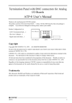
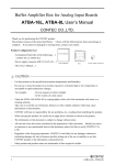
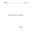
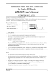
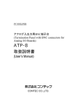
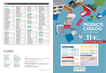
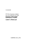
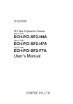
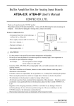
Termination Panel with BNC connectors
for Analog I/O Boards
ATP-8L User’s Manual
CONTEC CO.,LTD.
Thank you for purchasing the CONTEC product.
The product consists of the items listed below. Check, with the following list, that your package is
complete. If you discover damaged or missing items, contact your retailer.
Product Configuration List
User's Manual
- This User’s Manual…1
AI03
AI02
AI01
AI07
AI06
AI05
AI04
AO01
AO00
CN2
- Signal name label sheet…1
User's Manual
AI00
CN1
- ATP-8L Termination Panel…1
11
20
1
10
ATP-8L
Signal name label sheet
CAUTION
-
Use it in a regulated system requirements (temperature and humidity).
-
Do not use or store the product in a location exposed to extremely high or low temperature or
susceptible to rapid temperature changes.
Example: - Exposure to direct sun
- In the vicinity of a heat source
-
Clean the ATP-8L by wiping lightly with a soft cloth moistened with water or a cleaning solution.
Take care to avoid the use of benzene, thinners or other volatile solutions which may cause
deformation or discoloration.
-
CONTEC will bear no responsibility for any problems, etc., resulting from modifying this product.
-
When carrying the product, be careful not to apply direct vibration or shock to the board.
Notes
-
The information in this document is subject to change without notice.
-
All relevant issues have been considered in the preparation of this document. Should you notice
an omission or any questionable item in this document, please feel free to notify CONTEC CO.,
LTD.
-
Regardless of the foregoing statements, CONTEC is not liable for any damages whatsoever
(including damages for loss of business profits) arising out of the use or inability to use this
CONTEC product or the information contained herein.
-
Other product and product names are trademarks of their respective holder.
ATP-8L
1
ATP-8L User’s Manual
1. About the Termination Panel
ATP-8L are the termination panel with BNC connectors for CONTEC’s analog I/O board
AIO-160802L-LPE, AI-1616L-LPE, AO-1604L-LPE, ADA16-8/2(LPCI)L, AD16-16(LPCI)L,
DA16-4(LPCI)L, ADAI16-8/2(LPCI)L, ADI16-16(LPCI)L, DAI16-4(LPCI)L AIO-160802LI-PE,
AI-1616LI-PE, AO-1604LI-PE of LowProfile size and PC card ADA16-8/2(CB)L *1.
This terminal box eases your connection of external devices and signals.
Note that a part of the analog I/O signals cannot be used when AI-1616L-LPE, AI-1616LI-PE,
AO-1604LI-PE, AO-1604L-LPE, AD16-16(LPCI)L, DA16-4(LPCI)L, ADI16-16(LPCI)L and
DAI16-4(LPCI)L are used.
*1 For more details on this, refer to “5. Specifications”.
1.1. Features
Compact designing
With its compact designing, you can place this BNC connector terminal box at your Personal computer.
By removing the connection cable, you can carry this box with your easily.
Lightly designing by Aluminum
It is lightly designed by using an aluminum in consideration of portable.
Easy to connect external signals
Allow you to connect analog signal through a BNC cable.
through M3 screw terminals.
All other digital signals are connected
Signal name label sheet
A name label sheet of digital signals of AD board or cards is bundled.
Sticking this name label helps you to link the external digital signals to our board or PC-Card products.
2
ATP-8L
ATP-8L User’s Manual
2. Connect an Board
2.1. Terminal Pin and the Corresponding Board / PC-Card
Connector Pin Assignment
Table 1
Terminal Pin and the Related Board / PC-Card Connector Pin Assignment
Signal name on
Description
ATP-8L
Signal name on Supported Item
BNC connectors
AI00 - AI07
Analog inputs signal.
Analog Input00 - Analog Input07
AO00 - AO01
Analog outputs signal.
Analog Output00 - Analog Output01
Trigger input signal that starts one of analog to
AI External Start Trigger Input
Screw terminals
AISTART
AISTOP
AIEXCLK
AOSTART
AOSTOP
AOEXCLK
digital conversion sampling transactions.
Trigger input signal that stops an on going analog
AI External Stop Trigger Input
to digital conversion sampling transaction.
Clock input signal for analog to digital conversion
AI External Sampling Clock Input
transactions.
Trigger input signal that starts one of digital to analog
AO External Start Trigger Input
conversion sampling transactions.
Trigger input signal that stops an on going digital
AO External Stop Trigger Input
to analog conversion sampling transaction.
Clock input signal for digital to analog conversion
AO External Sampling Clock Input
transactions.
DI00 - DI03
Digital input signals.
Digital Input00 - Digital Input03
DO00 - DO03
Digital output signals.
Digital Output00 - Digital Output03
CNTGATE
Counter gate control input signal.
Counter Gate Control Input
CNTUPCLK
Pulse input signal for Up counting transaction.
Counter Up Clock Input
CNTOUT
Counter output signal.
Counter Output
DGND
Ground for all the digital signals.
Digital Ground
Reserved
Reserved.
Reserved
-
For an AIO-160802L-LPE, ADA16-8/2(LPCI)L, ADAI16-8/2(LPCI)L, AIO-160802LI-PE board
and ADA16-8/2(CB)L PC card
Eight channels of analog input signals, two channels of analog output signals, digital I/O signals,
counter I/O signals, trigger input signals for analogue I/O signals can be connected through ATP-8L
terminal box.
-
For an AI-1616L-LPE, AD16-16(LPCI)L, ADI16-16(LPCI)L, AI-1616LI-PE board
Only the first eight channels in sixteen channels of analog input signals, digital I/O signals, counter
I/O signals, trigger input signals for analogue I/O signals can be connected through ATP-8L
terminal box. The other analog input signals cannot be connected through ATP-8L terminal box.
-
For an AO-1604L-LPE, DA16-4(LPCI)L, DAI16-4(LPCI)L, AI-1616LI-PE, AO-1604LI-PE board
Only the first two channels in four channels of analog output signals, digital I/O signals, counter I/O
signals, trigger input signals for analogue output signals can be connected through ATP-8L terminal
box. The other analog output signals cannot be connected through ATP-8L terminal box.
ATP-8L
3
ATP-8L User’s Manual
2.2. Pin Assignment of Connector
Non Connect
Analog Ground
( for AO)
N.C
50
25
AO 00
AGND
49
24
AGND
Non Connect
Analog Ground
( for AO)
N.C.
48
23
AO 01
AGND
47
22
AGND
Analog Input 04
Analog Ground
( for AI)
AI 04
46
21
AI 00
AGND
45
20
AGND
Analog Input 05
Analog Ground
( for AI)
AI 05
44
19
AI 01
AGND
43
18
AGND
50
49
25
24
Analog Output 00
Analog Ground
( for AO)
Analog Output 01
Analog Ground
( for AO)
Analog Input 00
Analog Ground
( for AI)
Analog Input 01
Analog Ground
( for AI)
Analog Ground
( for AI)
AGND
17
16
15
Analog Ground
( for AI)
AI 06
42
41
40
AGND
Analog Input 06
Analog Ground
( for AI)
AI 02
AGND
39
14
AGND
Analog Input 02
Analog Ground
( for AI)
Analog Input 07
Analog Ground
( for AI)
AI 07
38
13
AI 03
AGND
37
12
AGND
Analog Input 03
Analog Ground
( for AI)
AO External Start AO START
Trigger Input
36
11
AI
START
AI External Start
Trigger Input
AO External Stop
Trigger Input
AO STOP
35
10
AI
STOP
AI External Stop
Trigger Input
AO External
Sampling Clock
Input
AO
EXCLK
9
AI
EXCLK
AI External
Sampling Clock
Input
Digital Ground
Digital Output 00
Digital Output 01
Digital Output 02
Digital Output 03
Digital Ground
Counter UP Clock
Input
DGND
DO 00
DO 01
DO 02
DO 03
DGND
CNT
UPCLK
DGND
DI 00
DI 01
DI 02
DI 03
DGND
CNT
GATE
Digital Ground
Digital Input 00
Digital Input 01
Digital Input 02
Digital Input 03
Digital Ground
Counter Gate
Control Input
Reserved
Reserved
CNT
OUT
Counter Output
Figure 1
11
12
13
14
4
2
1
33
32
31
30
29
28
8
7
6
5
4
3
27
2
26
1
2
3
15
16
17
18
DI01
DI03
DO01
DO03
4
AISTART DGND AOSTART DGND
Figure 2
27
26
Pin Assignment of Connector CN1
AISTOP AIEXCLK AOSTOP AOEXCLK
1
34
20
19
CNTGATE CNTUPCLK
5
6
7
8
DI00
DI02
DO00
DO02
9
10
CNTOUT Reserved
Pin Assignment of Digital Input and Output Signals (CN2)
ATP-8L
ATP-8L User’s Manual
2.3. Example of Using Signal Name Label Sheet
A name label sheet for M3 screw terminals is bundled with this ATP-8L terminal box.
You can stick one of these labels either on top of the screw terminals’ cover or at front side of ATP-8L
box by your preference, corresponding to your AD product.
11
12
13
14
15
AISTOP AIEXCL AOSTOP AOEXCLK DI01
1
2
3
4
AISTART DGND AOSTART DGND
16
17
DI03
DO01
18
19
20
DO03 CNTGATE CNTUPCLK
5
6
7
DI00
DI02
DO00
8
9
10
DO02 CNTOUT Reserved
SL-2983
Name Label Sheet
Stick one of these labels either
on top of the screw terminals’
cover or at front side of ATP-8L
box.
2.4. Application with Board / PC-Card
For the board such as AIO-160802L-LPE, Connect it to the CN1 by using the CONTEC option cable
(PCB50PS-**P). For the ADA16-8/2(CB)L, Connect it to the CN1 by using the CONTEC option
cable (ADC-68M/50M).
CAUTION
We suggest you to use a PCB50PS-0.5m option cable to connect the board and terminal box.
ATP-8L
5
ATP-8L User’s Manual
2.5. Connect External Signals
BNC Connectors
You use BNC connectors to
connect analog input and
output signals.
M3 screw terminals
You use M3 screw terminals
to connect digital signals.
3. Connection Drawing
ATP-8L
AI00 - 07
Analog Output 00 - 01
AO00 - 01
Digital Input 00 - 03
DI00 - 03
Digital Output 00 - 03
DO00 - 03
Analog Ground
Analog Ground
AI External Start Trigger Input
AISTART
AI External Stop Trigger Input
AISTOP
AI External Sampling Clock Input
AIEXCLK
AO External Start Trigger Input
AOSTART
AO External Stop Trigger Input
AOSTOP
AO External Sampling Clock Input
AOEXCLK
Counter Gate Control Input
CNTGATE
Counter Up Clock Input
CNTUPCLK
Counter Output
CNTOUT
Figure 3
6
Supported Item
Analog Input 00 - 07
Digital Ground
DGND
Reserved
Reserved
Connection Drawing
ATP-8L
ATP-8L User’s Manual
4. Dimensions
(18.6) 22
(12.5)
AI03
AI02
AI01
AI00
AI07
AI06
AI05
AI04
AO01
AO00
CN2
(2.2)
CN1
88
120
11
20
1
10
[mm]
Figure 4
Dimensions
5. Specifications
Table 2
Specifications of ATP-8L
Items
Supported Products
Specification
AIO-160802LI-PE, AI-1616LI-PE, AO-1604LI-PE, AIO-160802L-LPE,
AI-1616L-LPE, AO-1604L-LPE, ADA16-8/2(LPCI)L, AD16-16(LPCI)L,
DA16-4(LPCI)L, ADAI16-8/2(LPCI)L, ADI16-16(LPCI)L,
DAI16-4(LPCI)L, ADA16-8/2(CB)L
Analog Input
8ch (BNC connector, AI00 - AI07)
Analog Output
2ch (BNC connector, AO00 - AO01)
Control input of analog I/O
6ch (Screw terminals, AISTART, AISTOP, AIEXTCLK, AOSTART,
AOSTOP, AOEXTCLK)
Digital Input
4ch (Screw terminals, DI00 - DI03)
Digital Output
4ch (Screw terminals, DO00 - DO03)
Counter I/O
1ch (Screw terminals, CNTUP,CNTCLK,CNTOUT)
Operating Conditions
0 - 50ºC, 10 - 90%RH (no condensation)
Dimensions (mm)
120(W) x 40.6(D) x 88(H)
(Not include the height of screw terminal block and rubber feet)
Weight
ATP-8L
240g
7
ATP-8L User’s Manual
Table 3
Specification of Interface Connector CN1
Type of Connector
10250-52A2JL[mfd by 3M] equivalent
Type of mating connector
10150-6000EL[mfd by 3M] equivalent
AIO-160802L-LPE, AI-1616L-LPE, AIO-160802LI-PE, AI-1616LI-PE,
Connecting Cable
AO-1604LI-PE, AO-1604L-LPE, ADA16-8/2(LPCI)L, AD16-16(LPCI)L,
DA16-4(LPCI)L, ADAI16-8/2(LPCI)L, ADI16-16(LPCI)L, DAI16-4(LPCI)L
: PCB50PS-0.5P, PCB50PS-1.5P (Option)
ADA16-8/2(CB)L : ADC-68M/50M (Option)
Specification of Terminal Block
Screw type
OTB-55-20P-C mfd by Osada
Suitable Y-type terminal C3A mfd by JST Mfg. Co., Ltd.
M3
Dimension of
Y-type
terminal
[mm]
Dimensions
of Terminal
[mm]
6.4
5.6
Terminal
3.2
Table 4
19
8.8
11.1
15.8
7.62
Copyright 2003 CONTEC CO., LTD. ALL RIGHTS RESERVED.
CONTEC CO., LTD.
May 2008 Edition
3-9-31, Himesato, Nishiyodogawa-ku, Osaka 555-0025, Japan
Japanese http://www.contec.co.jp/
English http://www.contec.com/
A-46-798 (LYDA713)
Chinese http://www.contec.com.cn/
05092008_rev4 [10152003]
No part of this document may be copied or reproduced in any form by any means without prior written
consent of CONTEC CO., LTD.