1
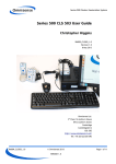
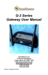
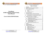
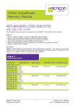
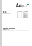
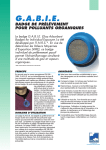
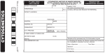
Series 500 Cluster Geolocation System
Series 500 Quick Start Guide
Chris Higgins, David Bartlett
RM008_QuickStart_1.0
Revision 1.0
25 April 2013
Omnisense Ltd.
3 Floor, St Andrew's House
59 St Andrew's Street
Cambridge
Cambridgeshire
CB2 3BZ
http://www.omnisense.co.uk/
Tel: +44 (0)1223 651390
rd
RM008_QuickStart_1.0
© Omnisense 2013
VERSION 1.0
Page 1 of 9
Series 500 Cluster Geolocation System
Table of Contents
1 System Components.................................................................................................3
2 Set up the hardware................................................................................................4
2.1 Unpack and charge the Cluster Nodes.....................................................................4
2.2 Set Up the CLS-503 (mini-ITX PC)...........................................................................4
2.3 Connect the gateway node to the CLS-503...............................................................5
2.4 Power up the system..........................................................................................5
3 Starting up for the first time......................................................................................6
3.1 The Status page................................................................................................7
4 Next step.............................................................................................................7
Revision History
Version
Date
Author
Notes
0.1
3/04/13
CH
Draft for review
0.2
17/04/13
DB, AT
Internal review
1.0
17/04/13
CH, DB
First Release
RM008_QuickStart_1.0
© Omnisense 2013
VERSION 1.0
Page 2 of 9
Series 500 Cluster Geolocation System
1 System Components
Please find:
Item
Description
Qty
1.1
GCN-523 Personnel node
1.2
GCN-523P High Performance personnel node
1.3
USB mains charger (dual)
1.4
USB to micro-USB adapter cables for GCN-523
2.1
GCN-533 Rugged node
2.2
GCN-533P High Performance rugged node
2.3
Mains charger and adapter cable for GCN-533
2.4
Solar panel and adapter cable for GCN-533
3.1
GCN-533C gateway device
3.2
USB power adapter cable for GCN-533C
3.3
USB serial port adapter cable for GCN-533C
4.1
GCN-553 gateway device plus antenna
4.2
USB serial adaptor cable for GCN-553 gateway
4.3
USB power adaptor cable for GCN-553 gateway
5.1
CLS-503 Collector (mini-ITX PC)
5.2
Power adaptor for Collector (12 V DC), with mains cable
5.3
Flat screen display monitor, with power and VGA cables
5.4
USB keyboard for Collector
5.5
USB mouse for Collector
5.6
Ethernet patch cable
6.1
S500Player Software
6.2
OMS-RM011 OMS500Player Tools Reference Manual
7.1
S500AnalysisTools Software
7.2
OMS-RM012 OMS500AnalysisTools Reference Manual
9.1
USB Memory stick containing documents and software
9.2
OMS-RM008 Quick Start Guide
9.3
OMS-RM007 API document
9.4
OMS-RM009 CLS 503 User Guide
9.5
OMS-RM010 Deployment guide
9.6
OMS-RM004 Cluster System Reference Manual
RM008_QuickStart_1.0
© Omnisense 2013
VERSION 1.0
Page 3 of 9
Series 500 Cluster Geolocation System
2 Set up the hardware
2.1 Unpack and charge the Cluster Nodes
Before using the system the Cluster nodes may need to be charged.
Connect the GCN-523 and GCN-533 to the chargers supplied with them using the adapter cables
provided.
2.2 Set Up the CLS-503 (mini-ITX PC)
Connect the PSU supplied to the CLS-503 and plug it into a mains socket.
If a monitor is provided with the system plug it into the mains and connect it to the CLS-503 using
the VGA cable supplied.
If a monitor is not supplied, any modern standard VGA or DVI monitor should work with the CLS503. A resolution of at least 1024x768 is recommended.
If the keyboard and mouse are supplied plug them into the first two USB ports as shown below. If
they are not supplied, any standard USB keyboard and mouse should work.
Using the Ethernet patch cable supplied connect the CLS-503 to a local LAN port. It is set up to
use DHCP to obtain a network address.
The picture below illustrates the required connections.
RM008_QuickStart_1.0
© Omnisense 2013
VERSION 1.0
Page 4 of 9
Series 500 Cluster Geolocation System
2.3 Connect the gateway node to the CLS-503
The description and picture below are for the GCN-553 gateway device, but the principle is the
same for the GCN-533C gateway although the gateway connectors are different.
Connect the USB to USB cable to the gateway and plug it into the third USB port on the back of
the CLS-503. This is to supply power to the gateway node.
Connect the communications cable into the fourth UISB port on the CLS-503, and plug the stereo
jack into the socket on the back of the GCN-553.
Fit the antenna to the antenna connector labelled “1” on the opposite end of the GCN-553 from
the USB connectors.
The picture below shows the back of the CLS-503 with all cables attached:
2.4 Power up the system
Turn on the monitor.
Turn of the CLS-503 by pressing the button on the front to the left of the product label. It will
illuminate blue.
If the gateway is a GCN-553, turn it on using the toggle switch just above the communications
cable. At least one of the LEDs on the top panel will illuminate.
RM008_QuickStart_1.0
© Omnisense 2013
VERSION 1.0
Page 5 of 9
Series 500 Cluster Geolocation System
3 Starting up for the first time
Turning on the PC it boots up, starts a web browser and shows the welcome page:
The system boots up and automatically logins in. The user is “oms” and the password is
“omspass”.
Go to the “Status” page, by clicking on the link on the left-hand side.
RM008_QuickStart_1.0
© Omnisense 2013
VERSION 1.0
Page 6 of 9
Series 500 Cluster Geolocation System
3.1 The Status page
When the system is not running the status table shows the state of play at the end of the last
run.The browser refreshes the table periodically.
The first column of the table is coloured red if a device has not been heard from recently. So if
the system is stopped, sooner or later all the devices will be marked as red.
Now click “start with graphics” to start Omnisense's location engine software.
RM008_QuickStart_1.0
© Omnisense 2013
VERSION 1.0
Page 7 of 9
Series 500 Cluster Geolocation System
4 Graphical display
The status page should now be saying that the system is running but the graphical tools can take a
little time to start up. Please be patient! The first screen displayed shows a matrix of the signal
strengths between all of the devices. It will look something like the picture above.
Strongly red boxes mean a good signal strength between the devices. Cooler colours indicate
weaker signals.
Omnisense's graphical tool has a number of screens but it only shows them one at a time. To
switch between them you need to type a single letter:
•
p to show the positions screen
•
r to show the rssi screen (the one above)
•
b to show the battery voltage screen
•
q to quit the application.
Try experimenting to switch between the screens. For example typing “p” moves to the positions
screen as in the next picture.
RM008_QuickStart_1.0
© Omnisense 2013
VERSION 1.0
Page 8 of 9
Series 500 Cluster Geolocation System
In this diagram the coordinator device is positioned at the origin and all the other devices are
clustered a few metres away.
Detailed description of the graphics and what they mean can be found in Chapter 4 of the “Player
Tools User Manual” RM011.
5 Next steps
Now that you have the system running it is time to think about how you will deploy it. Please turn
to the “Series 500 Deployment Guide” for some guidance.
You may also want to know more about the CLS 503 computer. Perhaps you want to change the
keyboard layout? Please turn to the “Series 500 CLS 503 User Guide”.
RM008_QuickStart_1.0
© Omnisense 2013
VERSION 1.0
Page 9 of 9