1
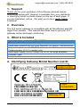
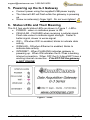
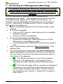
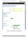
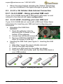
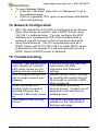
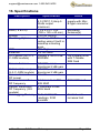
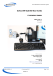
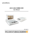
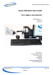
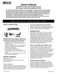
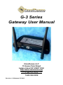
G-3 Series Gateway User Manual OmniSense LLC 72 Sams Point Road Ladys Island SC 29907 USA http://www.omnisense.com [email protected] 1.805.340.9625 1.843.522.0350 Revision 1.0 Released 5/7/2013 Table of Contents 1. SUPPORT ........................................................................................ 1 2. OVERVIEW ...................................................................................... 1 3. WHAT IS INCLUDED ....................................................................... 1 4. IDENTIFYING GATEWAY MODEL NUMBER AND ID ................... 1 5. POWERING UP THE G-3 GATEWAY ............................................. 2 6. STATUS LEDS AND THEIR MEANING .......................................... 2 7. ACCESSING G-3 MANAGEMENT WEB PAGE ............................. 3 8. CONNECTING G-3 GATEWAY TO THE INTERNET ..................... 5 8.1. W IRED ETHERNET INTERNET CONNECTION.................................. 5 8.2. W IFI INTERNET CONNECTION...................................................... 5 8.3. G-3-C-X 3G CELLULAR DATA INTERNET CONNECTION ................. 6 8.3.1. G-3-C-GSM - Using provided SIM card............................... 6 8.4. G-3-C-GSM - INSERTING YOUR OWN SIM CARD.......................... 6 8.5. GSM CONNECTION STATUS ....................................................... 7 9. USING G-3 GATEWAY IN DATALOGGING MODE ....................... 7 10. CREATE A MONITORING ACCOUNT ............................................ 8 11. ASSIGNING GATEWAY(S) TO A JOB SITE .................................. 8 12. INSTALLING SENSORS ................................................................. 8 13. VIEW SYSTEM DATA ONLINE ....................................................... 8 14. NETWORK CONFIGURATION ....................................................... 9 15. TROUBLESHOOTING ..................................................................... 9 16. SPECIFICATIONS ......................................................................... 10 17. DECLARATION OF CONFORMITY .............................................. 11 18. WARRANTY ................................................................................... 13 [email protected] 1.805.340.9625 1. Support Thank you for your purchase of OmniSense wireless remote monitoring equipment! Support is available from your distributor or directly by email or phone shown on the top of each page. If you are frustrated, call us. We want you to be a really happy customer! 2. Overview The G-3 series gateway is compatible with all OmniSense and GE HygroTrac sensors. This manual describes how to get your G-3 gateway online and begin monitoring. 3. What is Included Description G-3 series Data Acquisition Gateway Detachable Antenna with RP-SMA connector for Sensor Communication Detachable Antenna with RP-SMA connector for Cellular Communication (G-3-C-x models only) USB Power Supply 5VDC/1.0Amp (US, EU or UK plugs available) Ethernet Cable Instruction Manual 4. Identifying Gateway Model Number and ID model number Login Credentials Gateway ID Page 1 OmniSense G-3 Series Gateway [email protected] 1.805.340.9625 5. Powering up the G-3 Gateway Connect power using the supplied USB power supply The Internet LED will flash while the gateway is powering up Screw on antenna(s) finger tight. Do not over tighten! 6. Status LEDs and Their Meaning The G-3 has useful status LEDs as shown in Figure 1 - LEDs. POWER - when on indicates power is ON CELLULAR - FLASHES when receiving a cellular signal. Flash rate varies to indicate signal strength. Faster is better signal, slower is worse signal. WiFi - ON when WiFi is enabled, blinks to indicate data activity WAN/LAN - ON when Ethernet is enabled, blinks to indicate data activity INTERNET - When FLASHING indicates gateway is powering up. When ON indicates the G-3 has a working internet connection. When OFF the G-3 does NOT have a working internet connection. If its NOT ON the gateway is NOT ONLINE. Figure 1 - LEDs OmniSense G-3 Series Gateway Page 2 [email protected] 1.805.340.9625 7. Accessing G-3 Management Web Page As a general warning you should not change any settings outside of what is described in this manual. You can restore factory defaults by holding down the reset button for 20 seconds. The G-3 has a built in web server which serves up the management web pages. The management web server can be accessed directly using any PC, tablet or smart phone. To connect to the G-3 Management Web Page you must connect your PC, smart phone or tablet directly to the G-3 using either WiFi or hard wired Ethernet. Power on gateway and wait for the "Internet" LED to stop blinking to connect using WiFi From your PC, tablet or smart phone scan for available wireless networks Connect to SSID "OmniSense" to connect using hard wired Ethernet Connect G-3 Gateway's WAN/LAN port to your PC's Ethernet port using Ethernet cable You should see the "WAN/LAN" Link LED go on solid or blink open a web browser and enter "http://omnisense" in the address field You should then see a login page (see Error! Reference ource not found.) prompting for username and password. Use the default username and password from the label on the bottom of the gateway. TIP - The default username is "root" and the default password is the gateway ID. Note password and username are case sensitive and all letters are lower case. TIP - From the login page with no username or password required you can quickly get useful status like current cellular signal strength and number of active sensors since gateway was turned on. Bookmark this page for easy access. Page 3 OmniSense G-3 Series Gateway [email protected] 1.805.340.9625 Figure 2 - G-3 Management Login Web Page OmniSense G-3 Series Gateway Page 4 [email protected] 1.805.340.9625 8. Connecting G-3 Gateway to the internet To view your data in real time your gateway must have a internet connection. The G-3 can connect using Cellular (on G-3-C models), WiFi or hard wired Ethernet connections. Follow the steps in this section to connect the G-3 to the internet. To use your G-3 gateway in datalogging mode see section 9. power on gateway as described in section 5 follow the steps in either section 8.1, 8.2 or 8.3 depending on your method of connecting to the internet, to establish an internet connection If you have a internet connection then after a delay of up to 60 seconds you should see the "Internet" LED go on solid if the Internet LED does not go on the gateway is not talking to our server and your internet connection is not working. Check the troubleshooting guide in section 15 and/or our web site forum at shop.omnisense.com for troubleshooting tips. 8.1. Wired Ethernet Internet Connection Typically this is zero configuration and you do not need to access the G-3 Management Web Page when using a wired Ethernet connection Connect the gateway's WAN/LAN Ethernet port using the supplied Ethernet cable to your LAN, router, cable modem, DSL modem etc. to establish an internet connection You should see the "WAN/LAN" Link LED go on solid or blinking 8.2. WiFi Internet Connection login following instructions in section 7 Mouse over the "Network" drop down menu and click on "WiFi" click "Scan" and you should see a list of available wireless networks Click "Join Network" for the network you wish to join If the network you are joining uses wireless security then on the next page " Join Network: Settings" enter the "WPA passphrase" then click "Submit". On the next page do not change any of the default settings. Scroll down to the bottom and click "Save & Apply" Page 5 OmniSense G-3 Series Gateway [email protected] 1.805.340.9625 When the page finishes reloading the "Status" field shows you are connected if the signal strength is greater than 0% 8.3. G-3-C-x 3G Cellular Data Internet Connection 8.3.1. G-3-C-GSM - Using provided SIM card If your G-3-C-GSM came with a SIM card it will power on and connect to the internet with zero configuration. 8.4. G-3-C-GSM - Inserting your own SIM card If your G-3-C-GSM did not come with a SIM card follow these instructions for inserting your SIM card and configuring your connection Accessing the USB Stick MODEM 1. Open the gateway case by removing the 4 screws on the bottom of the gateway 2. Loosen two red thumb screws 3. Remove USB Stick MODEM to allow for access to SIM slot Inserting the SIM Card (see Figure 3 - Inserting the SIM Card) 1. Skip step 1 since the cap is already removed 2. Pull out the SIM card holder 3. Insert your SIM card into the holder as shown 4. Place the SIM card holder (with the fitted SIM) back in your USB modem Figure 3 - Inserting the SIM Card OmniSense G-3 Series Gateway Page 6 [email protected] 1.805.340.9625 Reassembly Insert USB Stick in its original position. Make sure it is fully inserted. Tighten two red thumb screws finger tight make sure Antenna connector is fully seated Close gateway case, insert 4 screws into bottom of case and hand tighten Configuring GSM Connection Login following instructions in section 7 Click on "Network" Click on "Edit" for the "WAN_3G" interface Enter the APN and optionally the PIN, Username and Password Click "Save & Apply" at the bottom of the page After about 30 seconds you should see the status show "Connected: 0h 0m 5s" as well as see signal strength, the carrier name (i.e. "T-Mobile") and other SIM and MODEM information. While its a good idea to write this down this same information will be available on the OmniSense web site's gateway detail page should you need it. 8.5. GSM Connection Status The rate at which the "Cellular" LED flashes varies with signal strength and faster is better The "Internet" LED comes on when a connection with the OmniSense server has been successfully made more detailed connection status is available on the G-3 Management Web Page which is accessed as described in section 7. 9. Using G-3 gateway in Datalogging mode The G-3 Gateway always operates in Datalogging mode if it has no internet connection. In this mode no internet connection is required when collecting data and all sensor readings are stored in the local FLASH drive. To upload the saved data to our server the Gateway will require an internet connection. Once it has an internet connection the stored data is automatically uploaded to our server. The time to upload all data varies depending on the amount of sensor readings being uploaded and the speed of the internet connection. Data is uploaded oldest readings first. By Page 7 OmniSense G-3 Series Gateway [email protected] 1.805.340.9625 default the Gateway can store 262,144 readings after which oldest readings are overwritten. This can be increased to more than 32M readings if required. 10. Create a Monitoring Account If you already have an account you do not need to create a new account. The OmniSense G-3 gateway can be used with existing GE HygroTrac accounts however all new accounts should be opened on the OmniSense Web site. go to http://www.omnisense.com, hover your mouse over "My Account" then click "create new account" fill in the form to create your account making sure you select the pricing plan that fits your use model You will be prompted to create a new job site. Fill in the form that describes the site you wish to monitor 11. Assigning Gateway(s) to a job site after completing the site setup in step 1 you will be on the "My Account" page. Click on "jobs Sites" to go to your job sites and you should see the job site you just created. Click on the "Gateways" link on that page to manage the gateways assigned to that job site Click on the "Add a new gateway" button Enter the Gateway ID found on the bottom label of the G-3 gateway and a description and click "Save" 12. Installing Sensors There are too many variables to address in this guide however case studies of typical sensor installations can be seen here http://shop.omnisense.com/blog. 13. View System Data Online Login at http://www.omnisense.com Click on "Jobs Sites" to go to the job sites page. To View Sensor Data From the "Jobs Sites" page click on "Sensors" to go to the sensors page. Click on any sensor reading to view a graph of that data Note you may have to wait up to 5 minutes for a sensor to show up on the sensors page OmniSense G-3 Series Gateway Page 8 [email protected] 1.805.340.9625 To view Gateway Status From the "Job Sites" page click on "Gateways" to go to the gateways page Click on a gateway ID to open a new window with details about that gateway 14. Network Configuration WiFi - By default the G-3's WiFi is configured as an Access Point (also known as master) with a DHCP Server using 192.168.1.x address range. You can configure the WiFi interface as a simultaneous WiFi Client as described in section 5 and still connect to the G-3 as an access point. Hard Wired Ethernet - The G-3 automatically acts as a DHCP Server with IP=10.168.1.98 if no other DHCP server is detected on the network or it will automatically act as a DHCP client if a DHCP server is detected 15. Troubleshooting PROBLEM "Cellular" LED Blinking (you have signal) but "Internet" LED never comes on (not getting internet connection) After changing settings you can no longer access your gateway When connected to a building LAN via wired or wireless Ethernet, the "Internet" LED never comes on The network uses a Proxy Server Page 9 SOLUTION If you are using your own SIM card check your APN, Username and Password settings Restore factory default settings by pressing the reset button for 20 seconds or until ALL LEDS blink on then off Your network is blocking internet access. Contact your IT department and ask them to enable access Configure the proxy server IP address on the "OmniSense" Settings web page OmniSense G-3 Series Gateway [email protected] 1.805.340.9625 16. Specifications Description Power Size (l x w x h) Weight Mounting Options WiFi Ethernet 3G Cellular (on G-3C-GSM models) Sensor Antenna Cellular Antenna (on G-3-C-GSM models) Sensor transmitter RF power Sensor transmitter RF frequency Sensor transmitter RF frequency (-EU models) Datalogging Memory Specification 100-240 VAC input, 5.0 VDC/1.0 Amp 5 Watts output maximum 7.5 x 4.9 x 1.6 in. (190 x 125 x 40 mm) 13.0 oz (429 g) Desktop. Wall or ceiling using 2 built in teardrop mounting eyes. 802.11gn 10/100 Mb/s Huawei E160G USB MODEM Notes USB power supply with Mini B type connector. Excluding Antenna(s) US models come with T-Mobile SIM Card RP-SMA, omnidirectional 2 dBi gain RP-SMA, omnidirectional 2 dBi gain 10 mW 64 channels in 902928 MHZ 3 channels in 868 MHz band FCC ISM band Default 262,144 readings, 32M possible Contact us to increase limit OmniSense G-3 Series Gateway Page 10 [email protected] 1.805.340.9625 17. Declaration of Conformity We, OmniSense LLC 72 Sams Point Road Ladys Island SC 29907 declare under our sole responsibility that the OmniSense Monitoring System to which this declaration relates, is in conformity with the following standards: For US and Canada Models Only FCC Part 15 This Product Contains Transmitter Module FCC ID: RY20002 and Transmitter Module FCC ID:TE7MR3020 This equipment complies with Parts 15 of the Federal Communications Commission (FCC) rules for the United States. Operation is subject to the following two conditions: (1) this device may not cause interference, and (2) this device must accept any interference, including interference that may cause undesired operation of the device. The equipment has been tested and found to comply with part 15 of the FCC rules. These limits are designed to provide reasonable protection against harmful interference in a residential installation. This equipment generates uses and can radiate radio frequency energy and, if not installed and used in accordance with the instructions, may cause harmful interference to radio communications. However, there is no guarantee that interference will not occur in a particular installation. If this equipment does cause harmful interference to radio or television reception, which can be determined by turning the equipment off and on, the user is encouraged to try and correct the interference by one or more of the following measures: • Reorient or relocate the receiving antenna. • Increase the separation between the equipment and receiver. • Connect the equipment into an outlet or on a circuit different from that to which the receiver is connected. • Consult the dealer or an experienced radio/TV technician for help. Page 11 OmniSense G-3 Series Gateway [email protected] 1.805.340.9625 FCC Part 15 Warning: Changes or modifications to this unit not expressly approved by the party responsible for compliance could void the user's authority to operate the equipment. Industry Canada (IC) This Product Contains Transmitter Module IC ID:6474A-0002. This digital apparatus does not exceed the Class B limits for radio noise emissions from digital apparatus set out in the interference causing equipment standard entitled Digital Apparatus, ICES-003 of Industry Canada. This device complies with Canadian RSS-210 regulations. NOTICE: The Industry Canada (IC) label identifies certified equipment. The Department does not guarantee the equipment will operate to the user’s satisfaction. For EU Models Only Data Acquisition Gateway The G-3 Series Gateway is in conformity with the following standards: EN55022:2006+A1:2007 EN 55024:2010 EN60950-1:2006 + A11:2009 + A1:2010 + A12:2011 following the provisions of the 2004/108/EC Electromagnetic Compatibility (as amended) and 2006/95/EC Low Voltage Directive (as amended). Sensors The Sensor Module is in conformity with the following standards: EN300 220-3 V1.1.1 (2000-09) EN301 489-3 V1.4.1 (2002-08) following the provisions of the Radio Equipment and Telecommunications Terminal Equipment. (R&TTE) directive: Directive 1999/5/EC. Ladys Island - May 7, 2013 Chris Hoogenboom President, OmniSense LLC OmniSense G-3 Series Gateway Page 12 [email protected] 1.805.340.9625 18. Warranty OmniSense LLC warrants its products against defects in material and workmanship for 12 months from the date of shipment. Products not subjected to misuse will be repaired or replaced. OmniSense LLC reserves the right to make changes without further notice to any products herein. OmniSense LLC makes no warranty, representation or guarantee regarding the suitability of its products for any particular application nor does OmniSense LLC assume any liability arising out of the application or use of any product or circuit and specifically disclaims all liability without limitation for consequential or incidental damages. The foregoing warranties are exclusive and in lieu of all other warranties, whether written, oral, implied or statutory. No implied statutory warranty of merchantability or fitness for particular purpose shall apply. Page 13 OmniSense G-3 Series Gateway