1
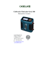
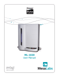
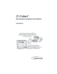
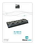
Optimizer Collect
User Manual
for MFC/MFM calibration with
Integrator 110 and Drycal
Table of Contents
Overview of Optimizer Collect..............................................................................................................................2
PC Requirements....................................................................................................................................................................2
Equipment Required...............................................................................................................................................................2
Installing Collect on your PC.................................................................................................................................2
Installation and registration.....................................................................................................................................................2
Communication port setup......................................................................................................................................................2
Calibration Setup.................................................................................................................................................3
MFC Calibration Setup.............................................................................................................................................................3
Gas Connection Diagram.................................................................................................................................................3
Electrical Connection to Integrator 110............................................................................................................................3
MFC calibration using Collect...........................................................................................................................................3
MFM Calibration Setup............................................................................................................................................................7
Gas Connection Diagram.................................................................................................................................................7
Electrical Connection to Integrator 110............................................................................................................................7
MFM calibration using Collect..........................................................................................................................................7
Appendix..........................................................................................................................................................11
Integrator 110 DB25 Pin Diagram.......................................................................................................................................... 11
Glossary............................................................................................................................................................................... 11
Troubleshooting.................................................................................................................................................................... 12
Technical Support..............................................................................................................................................12
Accuracy
Reliability
Convenience
1
Overview
Bios Optimizer is a windows based application that provides comprehensive features and functionalities for capturing
gas flow data from Bios DryCal calibrators and then importing this data directly to Microsoft Excel. The method outlined in this manual is for automatic multi-point calibration of analog mass flow device such as Mass Flow Controllers
(MFC) and Mass Flow Meters (MFM).
PC Requirement
• Windows® XP, Windows® Vista (32 bit version)
• Microsoft Excel® 2000, 2003, 2007
• RS232 port, or if your PC does not have an RS-232 port you will need a USB to RS-232 adapter
Equipment Required
•
•
•
•
Integrator 110
DryCal
MFC
MFM
Installing Collect on your PC
Installation Steps
1. Close all open applications, insert the Bios Optimizer Collect CD into your PC.
2. The setup wizard runs automatically. Click Software Installation on the installation screen.
3. Chose Next or Accept to confirm prompts as necessary.
For users outside USA, go to http://www.labtronics.com/DI/Downloads/Software-Updates.htm and download
Collect v6.1 Service Release 2 for the update if the regional and language options of your PC are not set to English.
Click on ‘Read me’ for the downloading procedure.
Registration
1.Launch Collect by clicking on the desktop shortcut or select it from your program list. Note the registration
code on the Registration screen and also the CD Key on the front of your Bios supplied CD jacket.
2. Go to web site http://www.mesalabs.com/bios-software-validation/.
3.Enter the required information in ‘Bios Optimizer Collect Activation’ screen and click ‘Submit’. An activation
code will be sent to you via email.
4.Log into Windows® as a User with Administrator rights and Launch Collect by clicking the desktop shortcut or
selecting it from your program list. On Windows® Vista, you must right-click on the icon and select ‘Run as
Administrator’ even if you are logged on as an Administrator to enter the activation key.
5. Enter the Activation Key on the Registration screen and click Ok to complete the registration.
Communication Port Setup
1. Launch Collect by clicking on the desktop shortcut or select it from your program list.
2. Select the method on the method list and then click on Edit gMethod Connection from the tool bar.
3. Click Edit on Method Connection window and then Setup on the Communication Setup window.
4.Select RS232 Setup tab on the RS232 Collector Setup window and select the correct communication port
that the serial cable is connected to under COM, verify the settings below and then click OK.
•
•
•
•
•
Baud Rate
Data Bits
Parity
Stop Bits
Flow Control
9600
8
None
1
None
2
Calibration Setup
Gas Connection Diagram
Integrator
110
Gas Supply
Pressure
Regulator
Pressure
Guage
MFC
DryCal
Pic 1: Gas Connection Diagram
• Connect the MFC and the DryCal to the gas supply as shown above.
• Connect tubing on the pressure gauge to the MFC inlet and on the MFC outlet to the DryCal inlet.
• Leave the DryCal Outlet open to the ambient.
•T
urn the gas supply on and adjust the pressure of the gas flow using the pressure regulator to the
rated inlet pressure of the MFC.
Electrical Connection to Integrator 110
Power Supply
PC
DryCal
MFC
Pic 2: Electrical connection to Integrator 110
• Connect a serial cable from the DryCal to the DryCal designated serial port of Integrator 110.
• Connect a serial cable from your PC to the PC designated serial port of Integrator 110.
• Connect a MFC configured cable from the MFC to the MFC designated parallel port of Integrator 110.
MFC multi-point calibration using Collect
1.Turn on the DryCal, access to the setup menu on your DryCal instrument and set the Cal Type to standardized
‘Std’ and Temp Corr to standardizing temperature of the MFC. Set the Sensor Factor to its default value‘1.000’.
2. Turn on the Integrator 110.
3.Launch Collect by clicking on the desktop shortcut or select it from your program list. Double click
MFC CALIBRATION on the method list (see pic. 3) and an Excel spreadsheet containing a Collect
sub-tool –bar will appear, (See pic. 4).
3
Pic 3: Collect FrontPage
4.Enter data in the ‘MFC Calibration Data Sheet’ and ‘Calibration Equipment Used’. Items in green indicates a
field where a data is entered, blue indicates a drop down where an item is selected and red indicates a field
where either data is entered or an item is selected that affects the operation and outcome of the flow rate
calibration The following items effect the calibration operation.
•M
FC Input Signal and MFC Output Signal selection must match the signal type used by the MFC
you are calibrating.
•M
FC Warm up Time and Time between Set points determines the timed delay in minutes on start
up and between set point changes. A time of 30 seconds can be expressed as 0.5 minutes.
•M
FC Rated Accuracy This entry will determine if the software declares the MFC in tolerance or
out of tolerance. Accuracy type is selected to either percent of Reading or as percent of Full Scale.
•N
o of Rdg in a setpoint This is the number of DryCal readings that will be taken per set point.
A higher number of readings will lead to improved accuracy, but takes longer to execute.
Collect
Toolbar
Pic 4: MFC calibration data sheet
4
5.Enter the desired set points at which the MFC will be checked in the ‘Set point’ column of ‘Calibration Check
Data’. A set point of 10% is entered as 10. The ‘Set point’ column can be populated with multiple set points
with any value from 0 to 100 and in any order. Collect will execute the setpoints sequentially. See pic 5.
Test
Message
Populate
Setpoint
Column
Collect
Toolbar
Delete MFC and
DryCal Flow values
before starting a test
Pic 5: Calibration Check data fields before starting a test
6.If previous ‘MFC Flow’ and ‘DryCal Flow’ values exist, delete those from the spreadsheet before starting a
test. The flow values must be deleted for proper operation.
7.Click ‘MFC CALIBRATION’ on the Collect toolbar and select ‘Start’.
8.Click ‘MFC CALIBRATION’ on the Collect toolbar and select ‘Start Test’. The test will now run automatically.
During the test, the status of the test will be shown in a message box. The message box will show:
a)‘Wait for Warmup xxx Mins’ is displayed in the spreadsheet and the program will wait for the
assigned period of time in ‘MFC Warmup Time’ before collecting readings from the DryCal or MFC.
b)After the warmup period, ‘Wait for Valve Change xxx Mins’ is displayed and the program will wait for
the assigned period of time in ‘Time Between Setpoint’ between setpoint changes.
5
c)For a zero setpoint, the program checks the MFC only and calculates the error in terms of full scale.
d)For a non-zero setpoint, the DryCal is initiated to take the number of readings assigned in the ‘No of
Rdg in a setpoint’ and the average of the flow rate reading is recorded in the spreadsheet as DryCal
Flow value. ‘DryCal Reading In Progress’ is displayed while the DryCal is taking readings.
e)After completion of DryCal reading, MFC flow rate reading is recorded for that setpoint. ‘MFC Reading
In Progress’ is displayed while MFC is recording readings in the spreadsheet.
f)The program automatically selects the next setpoint and repeats steps b-e until it executes the last
setpoint. ‘Test is complete’ is displayed once it finishes recording the MFC flow rate reading of the last
setpoint.
Pic 6: Calibration check data fields after the test
9.The status of the MFC is displayed as either ‘MFC IS IN TOLERANCE’ or ‘MFC IS OUT OF TOLERANCE’
based on the tolerance assigned in ‘MFC Rated Accuracy’.
10.Click ‘MFC CALIBRATION’ on Collect toolbar and select ‘Close’.
ote: ‘DryCal Flow’ changes to ‘DryCal Flow Multiplied By Sensor Factor’ as the ‘Sensor Factor’ value entered is not its
N
default value 1.000.
6
MFM Calibration Setup
Gas Connection Diagram
Integrator
110
Gas Supply
Pressure
Regulator
Pressure
Guage
MFC
MFM
DryCal
Pic 7: Gas Collection Diagram
•C
onnect the MFC, MFM, and the DryCal to the gas supply as shown above.
•C
onnect tubing on the pressure gauge to the MFC inlet, MFC outlet to the MFM inlet and MFM outlet to the
DryCal inlet.
• L eave the DryCal Outlet open to the ambient.
•T
urn the gas supply on and adjust the pressure of the gas flow using the pressure regulator to the rated inlet
pressure of the MFC.
MFM
Power Supply
PC
DryCal
MFC
Pic 8: Electrical connection to Integrator 110
• Connect a serial cable from the DryCal to the DryCal designated serial port of the Integrator 110.
• Connect a serial cable from your PC to the PC designated serial port of the Integrator 110.
• Connect a MFC configured cable from the MFC to the MFC designated parallel port of the Integrator 110.
• Connect a MFM configured cable from the MFM to the MFM designated parallel port of the Integrator 110.
MFC multi-point calibration using Collect
1.Turn on the DryCal, access to the setup menu on your DryCal instrument and set the Cal Type to
standardized ‘Std’ and Temp Corr to standardizing temperature of the MFM. Set the Sensor Factor to
its default value‘1.000’.
2. Turn on the Integrator 110.
3.Launch Collect by clicking on the desktop shortcut or select it from your program list. Double click
MFM CALIBRATION on the method list and an Excel spreadsheet containing a Collect sub-tool
will appear (See Pic. 9)
7
Collect
Toolbar
Pic 9: MFM calibration data sheet
4.Enter data in the ‘MFM Calibration Data Sheet’ and ‘Calibration Equipment Used’. Items in green indicates a
field where a data is entered, blue indicates a drop down where an item is selected and red indicates a field
where either data is entered or an item is selected that affects the operation and outcome of the flow rate
calibration The following items effect the calibration operation.
•M
FC Input Signal and MFM Output Signal selection must match the signal type used by the MFM
you are calibrating and the type of MFC controlling the flow.
•M
FM Warm up Time and Time between Set points determines the timed delay in minutes on start
up and between set point changes. A time of 30 seconds can be expressed as 0.5 minutes.
•M
FM Rated Accuracy This entry will determine if the software declares the MFM in tolerance or
out of tolerance. Accuracy type is selected to either percent of Reading or as percent of Full Scale.
•N
o of Rdg in a setpoint This is the number of DryCal readings that will be taken per set point.
A higher number of readings will lead to improved accuracy, but takes longer to execute.
8
Collect
Toolbar
Test
Message
Populate
Setpoint
Column
Delete MFM and
DryCal Flow values
before starting a test
Pic 10: Calibration Check data fields before starting a test
5.Enter the desired set points at which the MFM will be checked in the ‘Set point’ column of ‘Calibration Check
Data’. A set point of 10% is entered as 10. The ‘Set point’ column can be populated with multiple set points
with any value from 0 to 100 and in any order. Collect will execute the setpoints sequentially.
6.If previous ‘MFM Flow’ and ‘DryCal Flow’ values exist, delete those from the spreadsheet before starting a
test. The flow values must be deleted for proper operation of this software.
7.Click ‘MFM CALIBRATION’ on the Collect toolbar and select ‘Start’.
8.Click ‘MFM CALIBRATION’ on the Collect toolbar and select ‘Start Test’. The test will now run automatically.
During the test, the status of the test will be shown in a message box. The message box will show:
a)‘Wait for Warmup xxx Mins’ is displayed and the program is waiting for the assigned period of time in
‘MFC Warmup Time’.
b)After the warmup period, ‘Wait for Valve Change xxx Mins’ is displayed and the program is waiting for
the assigned period of time in ‘Time Between Setpoint’ between setpoint changes.
c)For a zero setpoint, the program checks the MFM only and calculates the error in terms of full scale.
d)For a non-zero setpoint, the DryCal is initiated to take the number of readings assigned in the ‘No of
Rdg in a setpoint’ and the average of the flow rate reading is recorded in the spreadsheet as DryCal
Flow value. ‘DryCal Reading In Progress’ is displayed while the DryCal is taking readings.
e)After completion of DryCal reading, MFM flow rate reading is recorded for that setpoint. ‘MFM
Reading In Progress’ is displayed while MFM is recording readings in the spreadsheet.
f)The program automatically selects the next setpoint and repeats steps b-e until it executes the last
setpoint. ‘Test is complete’ is displayed once it finishes recording the MFM flow rate reading of the
last setpoint.
9
Pic 11: Calibration check data fields after the test
9.The status of the MFM is displayed as either ‘MFM IS IN TOLERANCE’ or ‘MFM IS OUT OF TOLERANCE’
based on the tolerance assigned in ‘MFM Rated Accuracy’.
10.Click ‘MFM CALIBRATION’ on Collect toolbar and select ‘Close’.
Note: ‘DryCal Flow’ changes to ‘DryCal Flow Multiplied By Sensor Factor’ as the ‘Sensor Factor’ value entered is not its
default value 1.000.
It is recommended to use an MFC that has a flow range similar to the MFM. If this can not be met, ensure that the
flows set by the MFC setpoints are within the MFM’s flow range.
10
Appendix
Integrator 110 DB25 Pin Diagram
Pin No.
Description
1
Power Ground
2
N/C
3
Signal Ground
4
+ 15V 1.7A, MFC /MFM Power
5
GND2
6
N/C
7
N/C
8
N/C
9
N/C
10
N/C
11
N/C
12
Signal Voltage in MFC/MFM
13
N/C
14
N/C
15
Signal Voltage out MFC
16
N/C
17
N/C
18
Signal Current out MFC
19
N/C
20
N/C
21
N/C
22
Signal Current in MFC/MFM
23
-15V_1.7A MFC-MFM Power
24
N/C
25
N/C
Note: Connect pin 1 and 5 as power ground for -15 V
Glossary
MFC Error to Setpoint: The error between the MFC input and output.
MFC Error to DryCal: The error between MFC output and the DryCal.
Error to Setpoint: The error between MFC input and the DryCal.
Sensor Factor: This factor is used only when surrogate or proxy gas (nitrogen or air) is used to calibrate an MFC or
MFM originally rated for a process gas other than proxy gas. Sensor Factor varies by MFC or MFM manufacturers. The
sensor factor is multiplication factor applied to the DryCal measured flow.
Warm-up Time: It is the time taken by MFC and MFM to reach stable temperature. The MFC and MFM are allowed to
warm up to achieve performance within the specification. By most manufacturers, the recommended warm up time is
45-60 minutes.
Time between Setpoints: It is the time taken by MFC for the valve to react to its corresponding signal setting for
full flow. The recommended time is one-minute minimum. With this option, the software provides MFC the specified
amount of time for its valve to open up before initiating a reading.
11
Troubleshooting
Here is a list of several things to check if you are having difficulty.
Step 1: Verify that the integrator 110 and the DryCal are turned on.
Step 2: Verify that the DryCal, PC, MFC, and MFM are connected to their designated ports in the Integrator 110.
Step 3: Verify that the PC cable is connected to the PC.
Step 4: Verify that the input and output signals in the spreadsheet values selected for the MFM and MFC are
correct for your MFC or MFM.
Step 5: Verify that the DryCal flow and MFC/MFM flow values are deleted before clicking ‘Start’ in the Collect
tool bar.
Step 6: Refer to the ‘Integrator 110’ manual and verify that the Integrator 110, DryCal, and MFC/MFM are operating correctly manually.
Step 7: If the steps 1-6 checks out successful, close the program, reopen, and restart the test.
Technical Support
Contact Bios at 973-492-8400 or e-mail [email protected] for any technical support
Bios, a division of Mesa Labs
10 Park Place
Butler, NJ, USA 07405
Phone: 973.492.8400
Toll Free: 800.663.4977
Fax: 973.492.8270
Email: [email protected]
web: www.mesalabs.com
© 2013 Mesa Labs MK01-35 Rev C
12