1
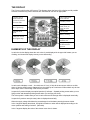
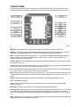
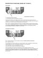
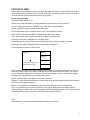
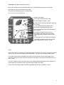
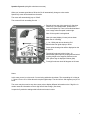
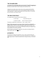
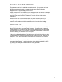
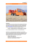
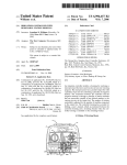
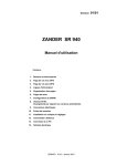
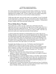
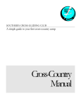
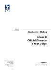
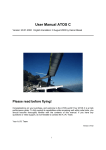
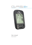
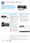
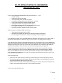
PILOT NOTES FOR THE C3 VARIOMETER
INSTALLED IN "KJJ"
The C3 offers a standard up/down audio vario just like an XK10 ...... plus
•
•
•
•
•
•
•
•
•
A digital averager
A speed to fly director with audio
A netto (air-mass) vario in speed to fly mode
Automatic switching between climb and speed to fly modes
A self contained pressure transducer digital altimeter
A final glide calculator with graphic/numeric display
Easy in flight adjustments for L/D, ballast, bugs and Mc.Cready
User adjustable settings for a host of parameters
Automatic recording of statistics for the last three flights
When connected to a separate GPS receiver it can
•
•
•
Take distance information from the GPS
Calculate wind strength and direction from GPS derived drift measurements
Provide final glide calculations to destination including around turning points
The instrument may seem to be complicated however it has been configured to suit "KJJ" and if used in
the manner advised herein it is almost as easy to use as an XK10. You simply switch on and go.
The instrument offers numerous configurations and options to suit the glider in which it is installed and to
satisfy the personal preference of the pilot. It is clearly not practical to have every pilot in the club making
changes to the setup and to the type of information to be displayed. In the interests of flight safety the
CFI insists that individuals should not alter any of the basic settings without prior approval.
This document does not purport to be an authoritative user manual. It aims to present the minimum
amount of information you need in order to understand basic use of the instrument with an attached
GPS, to soar at Bellarena and to use the final glide calculator to help you return to Bellarena safely.
Some elements of the manufacturer's manual are reproduced here and that manual can be seen in full
on the manufacturer's web site.
Some important notes...
•
•
•
Please take care when boarding or vacating to avoid breaking the C3 switchgear with your boots.
The instrument has been set up to display speeds in knots, height in feet and distances in nautical
miles (except analogue dials that remain in m/sec).
Until we have time to install manual switches, the changeover between vario mode and speed to fly
mode is executed automatically by the C3 and is related to airspeed.
If you have any queries please ask.
T. Snoddy
1
THE DISPLAY
The C3 has a multi-function LCD screen. This diagram shows the layout of the display and all possible
elements. Note that only certain elements are illuminated at one time as appropriate.
Circular vario in
climb mode and
speed to fly director
in cruise mode
Glide path arrows
above glide slope
Selected cursor
point
Glide path arrows
below glide slope
Vario climb mode
circle indicator
Tendency arrows
Averager in climb
mode, netto (air
mass) in cruise
mode
Cursor points
Battery warning
4 segment display of
altimeter line
5 Segment display
of chosen cursor
position
ELEMENTS OF THE DISPLAY
In vario the circular display shows the vario value. A petal displayed in the upper half means you are
climbing, and a lower half display means you are descending.
In vario mode it displays a vario -- At a climb rate of 5 m/s (10 kts) all the arrows are visible; at a climb
above 10 kts the arrows start to disappear from the middle up to a maximum of 20kts where only the last
arrow stays visible. Descending is the reverse procedure.
In speed to fly mode it displays an optical speed to fly indicator -- Upward pointing arrows when you are
flying too fast and downward pointing arrows when you are flying too slowly.
The circle symbol is visible when you are in vario mode and an average value is displayed numerically.
In speed to fly mode a netto (air-mass) value is displayed numerically.
When the supply voltage falls below the preset danger level the battery warning becomes visible.
In the 4 segment display the altitude, final glide information or other data is displayed according to the
cursor position and setting of switch 3. (See table)
In the 5 segment display the value of the chosen cursor item is shown.
2
CURSOR ITEMS
The information displayed on the 5 segment line is controlled by positioning the cursor at one of the
cursor points. Where user input is appropriate, changes to the value may be made with the +/- switch.
Aver. speed - Shows you the average speed on the leg you are flying. This value is set to "0" at switch
on.
Waypoint - Will indicate WP:GPS showing that distance information is taken from the GPS
Distance - The distance being used in the final glide calculation. If the GPS is in GOTO mode it will be
the distance to the active waypoint. If in route mode then the distance to final destination.
Wind - If the GPS is active and you have flown a circle recently, the wind direction and strength will be
shown. Otherwise you may see WIND:M and you may use the +/- switch to enter a head wind as
negative or tail wind as positive value.
Arrival height - Shows the required arrival height at the way point/destination. This has been set at 950
feet shown as 95 ft x 10
Volume - With Vol. you regulate the volume of the vario tones. The volume will increase automatically as
you fly faster. See later note concerning the external volume knob.
L/D - This shows the anticipated glide angle (GZ). For "KJJ" with 20m tips use 44. In 18 metre mode use
40. A quick in-flight correction (e.g. for bugs on wing) is possible.
W/L - Shows the wing loading (GF) in kilos per square metre. This has been entered as 35 kgs/sq m for
"KJJ" in 20m mode assuming two well-fed pilots and no water ballast. Use 37 kgs/sq m for 18 metre
mode.
Height - When the instrument is switched on the altimeter automatically shows QFE "0" feet.
Bat - Shows battery voltage.
Temp - Shows outside temperature from a probe in the front vent which must be open to enable
accurate readings.
McCready - Will show "0" at switch on. Set a suitable McCready value if required.
Average climb - Shows the value of the last thermal used. Thermal is defined as the time from switching
from speed to fly mode to vario mode and then switching back again from vario mode to speed to fly
mode. This value will be less than the average shown over 20 seconds. The value is set to "0" at switch
on.
Note - Switching on the instrument puts the following values to 0 :- average speed, wind, McCready and
average climb. The cursor point is set to volume.
3
DESCRIPTION OF SWITCHES (FROM LEFT TO RIGHT)
Power Switch
1 = C3 switched on with vario and speed to fly delay 1 – Use this position for normal use.
0 = C3 switches off after 9 seconds
2 = C3 switched on with vario and speed to fly delay 2
When the power switch is in the middle position 0 the C3 is switched off, but it does not switch off
immediately. It shows AUS on the display and after 9 seconds it switches off totally. If the power switch is
returned to 1or 2 before the expiry of 9 seconds the C3 is switched on.
Note: If the C3 is accidentally switched off in flight a loud audible warning is sounded, and at the bottom
of the screen a countdown begins (AUS 9…0) and the C3 switches off. If the switch is moved to position
1 or 2 before the countdown is complete the C3 will resume operation. After switching on again all
previous settings are restored e.g. height if C3 is set to QFE.
Vario/Speed to Fly Switch
Vario = vario mode
Auto = automatic switch from vario to speed to fly mode – Use this position for normal use.
Sollf. = speed to fly mode
The Vario/Speed to Fly switch enables you to choose between a vario or a speed to fly indicator being
optically displayed on your C3, with acoustic information from your loudspeaker.
In the vario position a vario will be displayed on your C3.
In the Sollf. Position a speed to fly indicator will be displayed.
In the Auto position the C3 switches automatically from vario to speed to fly and vice versa.
The criteria for switching can be given on the one hand by flying faster than a certain air speed (vario will
be switched off and speed to fly indicator on) or by flying slower than a certain airspeed (vario will be
switched on and speed to fly indicator off); or on the other hand by using a pilot operated external switch
yet to be fitted.
4
Start/Stop Switch
Stop = flight computer stopped - height is generally shown on the 4 segment display but will vary with
cursor position
Start = flight computer started - the final glide calculator begins to work. The glide path arrows become
active, each arrow = 50 feet. Three up arrows means you are at last 150 feet above final glide slope. The
actual height above / below glide path is shown on the 4 segment display.
Cursor Switch
^ = moving the cursor upwards
v = moving the cursor downwards
Using the cursor switch, you can move the cursor to the desired position.
To get from one side to the other, you just step over the last item at the top or the bottom and the
cursor jumps to the other side. Pressing the cursor and the plus/minus switch down together resets the
cursor back to the top right of the display(Vol.).
Plus/Minus Switch
+ = increases the displayed value
- = decreases the displayed value
The plus /minus switch enables you to change the value of the items you choose with the cursor.
To decrease the value you press the switch down to -.
To increase the value you lift the switch to +.
If you hold down the switch the value will change continuously. (Note - you can make entries faster than
the processor can handle and overshoot your requirement, be patient !.)
5
LETS GO FLYING
We will assume that the basic set up has not been interfered with, that "KJJ" has 20m tips fitted, that no
water ballast loaded and that the crew are two well-fed pilots. The following routine will give you all that
you need from the instrument with the minimum of user input.
Firstly start up the GPS
Put aircraft master switch to "on"
Switch on the GPS instrument by pressing and holding the red button for a few seconds.
The GPS may give a warning on land data, if so, press "enter" to acknowledge.
Wait for the GPS to acquire satellites and to locate itself.
The GPS will switch from the satellite screen to one of the navigation screens.
Press "GOTO" and check that "BELA" (for Bellarena) is the active waypoint
If not, use the large rocker button to scroll down to "BELA" and press enter
Use large rocker button to highlight "ok" and press "enter "
If the screen shows a map on the left and four data points on the right then setup is complete
Otherwise press "page" repeatedly until the required page is displayed
The required screen layout will look like this...
Map area
Speed
Distance
Bearing
Pointer showing position
and heading on map
Track
The map area will outline major roads, coastlines, lakes, towns and user defined waypoints. It does not
show any air-space data. Your position is indicated by a pointer at the centre of the map. Your current
track is indicated by the direction of the arrow. The map is orientated "north up" and will scroll up/down
and left/right as required leaving your position at the centre.
Speed - This will indicate your speed over the ground in knots.
Distance - This will indicate the distance in nautical miles to the selected waypoint and this will be sent to
the C3 for the final glide calculations.
Bearing - This indicates the "true bearing" from your present position to the selected waypoint.
Track - This indicates your current "true" track over the ground. Making the track reading equal the
bearing reading will ensure that you travel straight towards the selected waypoint. If the track is less than
the bearing then turn right, if the track is more than the bearing then turn left.
Note:
When stationary, the pointer heading and track information is erroneous.
6
Now start up the C3
Move the "1/0/2" (leftmost) power switch upwards on the front panel unit.
The C3 will take a few seconds to start.
The 5 digit line will briefly say "WP:GPS" to indicate that it is receiving distance information from the GPS
The digital altimeter will be set to zero (QFE) and will subsequently indicate height above airfield level.
Note that the height is displayed in tens of feet.
Climb mode will be set.
The circle symbol will be visible.
Ensure that the "vario / speed to fly" switch on the front unit is set to Auto.
Move the centre switch on the front unit to "Start" to enable the final glide calculator.
Further inputs may be made from either front or rear panel units.
The cursor will be at Vol. You may adjust the audio volume as required by the +/- switch. (See later note
on volume control)
The volume will increase automatically as you fly faster.
If necessary, place the cursor at L/D, check that the 5 digit line reads GZ:44.
If necessary, move the cursor to W/L, check that the 5 digit line reads GF:35.
Set a Mc.Cready value if required.
Launch.
The C3 will enter speed to fly mode during the aerotow - the circle symbol will be extinguished.
7
Climb mode (with glide calculator set to start)
When you slow down below 52 kts after release the C3 will automatically change to climb mode
Climb and sink tones will be heard from the audio
The cursor will automatically jump to "Arrival height "
The screen will look something like this ......
Pseudo vario pointer
Circle symbol indicating climb mode
20 second digital averager in knots
Tendency arrow showing if thermal is improving
or decaying
1, 2 or 3 Glide path arrows showing 50 ft
above/below final glide slope per arrow
Cursor point showing what will be displayed on
the 5 digit line
The 4 digit line shows height in feet x 10
above/below glide slope for pre-set arrival /
safety height at the waypoint selected on the
GPS.
(A minus sign will be illuminated if below glide)
The 5 digit line shows pre-set arrival or safety
height at destination set at 95 x 10 feet
Notes:
In this case you are in climb mode. The averager shows a climb rate of 4.7 knots. The thermal is tending
to decay. You are 530 ft above glide slope for destination. Your pre-set arrival/safety height is 950 ft.
Your actual arrival height at destination will be the sum of the pre-set arrival or safety height plus or
minus the value shown on the 4 digit line. Beware the minus sign. In this case you are likely to arrive at
148 x 10 feet.
The cursor may be moved to any other cursor point to display different information on the 5 digit line. In
certain cases the information on the 4 digit line will also change. (See chart).
In vario mode the analogue dials will present a standard total energy vario display in m/sec.
8
Speed to fly mode (with glide calculator set to start)
When you increase speed above 58 kts the C3 will automatically change to cruise mode.
Speed to fly tones will be heard from the audio.
The cursor will automatically jump to "Wind".
The screen will look something like this ......
Pseudo pointer now giving speed to fly directions.
Pointer up = pull up/slow down, pointer down =
nose down/speed up. There is an audio dead band
over a range when the speed is about right.
Note: Circle symbol is extinguished
Netto (air-mass) display in knots (minus shown
when the air is sinking)
1, 2 or 3 Glide path arrows showing 50 ft
above/below final glide slope per arrow
Cursor point showing what will be displayed on the
5 digit line
The 4 digit line shows height in feet x 10
above/below glide slope for pre-programmed arrival
or safety height at the waypoint selected on the
GPS. (Minus sign is displayed if below glide)
Five digit line shows wind 180 degrees at 18 knots
Notes:
In this case you are in cruise mode. You are being advised to slow down. The surrounding air is rising at
1.7 knots. You are 53 x 10 feet above the required glide slope. The wind is from 180 degrees (true) at 18
knots.
The cursor may be moved to any other cursor point to display different information on the 5 digit line. In
certain cases the information on the 4 digit line will also change. (See chart).
In speed to fly mode the analogue dial will show air-mass in m/sec.
9
THE VOLUME KNOB
An external volume knob has been fitted to the rear panel. This enables the instructor to
turn the audio volume up and down quite easily as and when required. To enable use of
this knob you should leave the volume setting on the instrument at 100.
If the glider is to be flown solo the volume knob on the rear panel should be left at
maximum (full clockwise) and the volume can be regulated in-flight by means of the
cursor control and +/- control on the front panel in the normal manner. For solo flying
the rear unit does is not need to be active.
THE ANALOGUE DIALS
The analogue dials are programmed to indicate as follows:
In climb mode.............
In speed to fly mode....
normal total energy vario
netto or air-mass movements
These dials are calibrated in metres/second. 1 m/sec = approx 2 knots.
Beware ! When showing netto or air-mass in speed to fly mode, the analogue dial
shows air mass movements, not climb and sink of the glider. If you encounter air that is
physically rising at 1 knot or 0.5 m/sec the analogue dial will show this positive (up)
value but the altimeter will not be impressed. This feature informs you of what the air is
doing regardless of the speed of the glider.
N.B. If you put the C3 into speed to fly mode on the ground, the analogue dials will
show a positive value. This is not a fault.
ACOUSTICS
The acoustic tone works in vario mode from - 20 to + 20 kts. The sink acoustic is a
continuous tone. In climb the acoustic is a continuous and broken tone. In speed to fly
mode, flying too fast is a continuous and broken tone. Flying too slowly is a continuous
tone.
10
THE REAR SEAT REPEATER UNIT
The rear seat control unit is fitted with three switches only. All cursor items and basic
set-up options are configurable from the rear seat. It addition, it is possible to have a
different cursor item selected in the rear and thereby have different information
displayed on the 5 segment display of the rear unit.
Display choices made on the rear unit will not change the front unit however all changes
to volume, glide angle, wing loading, McCready, arrival height, altimeter sub-scale and
any of the basic setup items will be changed on the main unit and will be used in
calculations.
Note that on the rear unit the left-hand Switch, the power switch, is used only for
entering setup and statistics modes, it will not power up or switch off the main front unit.
Instructors must set the three left-most switches on the front unit before boarding.
SWITCHING OFF
When you wish to switch off the unit you should move switch on the front unit to "0" and
allow the C3 to shut down over a period of 10 seconds. You will see the 10 seconds
counting down on the 5 digit line. This ensures that the statistics of the last three flights
are preserved in memory. If you switch off via the aircraft master switch or just remove
the aircraft battery, the stored data will be corrupted.
If the unit is accidentally switched off in flight, the audio will emit a high pitch tone while
it counts down to off. Do not misinterpret this as the ‘thermal of the year’. Restoring the
switch to "1" or "2" before the C3 has counted down to 0 will return the unit to normal
operation.
When the aircraft power is switched off via the master switch, the GPS will switch to its
own internal battery power. To avoid running down these batteries switch off the GPS
by pressing and holding the red button until the screen goes blank.
11
INFORMATION DISPLAYED ON THE 4 & 5 DIGIT LINES
This table outlines the different items of information that can appear on the 4 & 5 digit lines according to
cursor position and setting of glide calculator switch
Cursor point
Display
Glide calculator at STOP
Glide calculator at START
4 digit line
Altitude feet x 10
Height above below glide slope ft x10
5 digit line
4 digit line
Average speed
Altitude feet x 10
Average speed
Height above below glide slope ft x10
5 digit line
4 digit line
WP:GPS
Altitude feet x 10
WP:GPS
Height above below glide slope ft x10
5 digit line
Distance to waypoint/destination
derived from the attached GPS
Wind component on track
Distance to waypoint/destination
4 digit line
Wind direction and strength
(If GPS active and circle flown
recently. Not active on ground)
Altitude feet x 10
Wind direction and strength
(If GPS active and circle flown
recently. Not active on ground)
Height above below glide slope ft x10
5 digit line
4 digit line
Safety height (95 ft x 10)
Altitude feet x 10
Safety (arrival) height (95 ft x 10)
Height above below glide slope ft x10
5 digit line
4 digit line
Volume
Altitude feet x 10
Volume
Height above below glide slope ft x10
5 digit line
4 digit line
Glide angle (GZ)
Altitude feet x 10
Glide angle (GZ)
Height above below glide slope ft x10
5 digit line
4 digit line
Wing loading in kgs/sq metre (GF)
QFE in millibars/Hp
Wing loading in kgs/sq metre (GF)
QFE in millibars/Hp
5 digit line
4 digit line
Altitude feet x 10
Altitude feet x 10
Altitude feet x 10
Height above below glide slope ft x10
5 digit line
4 digit line
Battery volts
Altitude feet x 10
Battery volts
Height above below glide slope ft x10
5 digit line
4 digit line
External temperature (vent open)
Altitude feet x 100
External temperature (vent open)
Height above below glide slope ft x10
5 digit line
4 digit line
Mc.Cready setting
Altitude feet x 10
Mc.Cready setting
Height above below glide slope ft x10
5 digit line
Average rate of climb last thermal
Average rate of climb last thermal
Aver. Speed
Waypoint
Distance
4 digit line
Height above below glide slope ft x10
Wind
5 digit line
Arrival height
Volume
L/D
W/L
Height
Batt
Temp
McCready
Average Climb
Wind information is conditional upon the glider being in flight, the GPS having acquired position and a
circle having been flown within a reasonable time.
12
BASIC SETUP
The C3 has been configured by entering values and making choices as follows....
ITEM
SHORTENED TO
UNITS
SET AT
Screen contrast
Polar curve - standard class
Compensation
External vario/speed to fly switch
Auto change from vario to speed to fly
Auto change from speed to fly to vario
Average of numeric vario
Vario delay 1
Vario delay 2
Speed to fly delay 1
Speed to fly delay 2
Average of netto vario
Low battery warning
Temperature adjustment
Frequency (pitch)
Broken tone
Auto volume control
English or metric units
Tendency arrows
Pressure
Indicated airspeed
Dead band on speed to fly
Altimeter setting at switching on C3
Glide path
Type of analogue instrument
Zero on analogue instrument
Maximum on analogue instrument
Setting for analogue instrument
Automatic wind setting
Cursor point for specific switch
combinations
Cursor point for speed to fly setting
Cursor point for vario setting
Vario/speed to fly change over via
GPS
KONTR
POLAR
KOMP
WOELB
V-OFF
V-ON
INTEG
VAR 1
VAR 2
SOL 1
SOL 2
NETTO
BAT-S
T-JUS
FREQ
TAKT
ALAUT
W:SI/W:ENG
TEND
DRUCK
IAS
S-NUL
QFE/QNH
G.PFAD
A:TYPE
A:NUL
A:MAX
A:V-N
WIND A:WIND M
C.FIX
0 to 30
1, 2, 3 or 4
-25 to +125
0 or 1
Knots
Knots
Seconds
Seconds
Seconds
Seconds
Seconds
Seconds
Volts
Celcius
-10 to +10
-10 to +10
0, 1, 2, 3, 4, or 5
Ft,Nm,ft./min,kts,hPa
Ft/min
HPa
Kts
Ft/min
0 or 1
0 or 1
0 or 1
-50 to +50
Percent
0, 1, 2, 3 or 4
0 or 1
0 to 13
18
2
0
0
58
52
20
1.2
2.6
1.2
2.6
10
11
N/A
0
6
3
W:ENG
80
N/A
0
80
1
1
0
0
89
4
1
6
C.V>S
C.S>V
GPS.VS
0 to 13
0 to 13
0 or 1
N.B.
4
5
0
Individuals should not attempt to change the basic setup without prior approval of
the CFI. This is a flight safety issue. The foregoing is given as a reference for
restoring lost settings however the C3 retains all these basic settings even if the
power is disconnected.
13