1
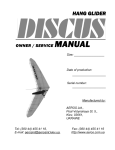
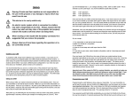
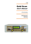
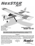
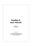
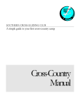
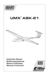
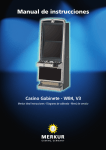
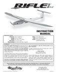
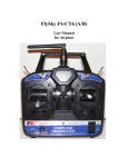
User Manual ATOS C
Version: 29.01.2002 English translation: 9 August 2002 by Heiner Biesel
Please read before flying!
Congratulations on your purchase, and welcome to the ATOS world! Your ATOS C is a high
performance glider. To fully exploit its capabilities while remaining well within safe limits, you
should become thoroughly familiar with the contents of this manual. If you have any
questions or need support, do not hesitate to contact the A.I.R. Team.
Your A.I.R. Team
Version: 01/02
1
1. Transport
•
By car
The carbon fiber D-tube can be damaged by point loading. For safe transport the glider should always
be supported by a large padded area. A ladder with several padded steps is one possibility. If the Dtube is supported at only two places, these supports need to be padded at least 4 inches in length,
and wide enough to support the full width of the glider. Anything less is likely to result in transport
damage, which can seriously reduce the strength of the main spar and the entire D-tube.
Do not tie down the glider too tightly, and use wide tubular of flat webbing to minimize point loading. If
the glider is likely to get exposed to rain, and especially to salt water, a watertight cover bag is strongly
recommended. If the ATOS C gets wet, dry it as quickly as possible to avoid staining the sail, or
causing corrosion of the metal parts. Exposure to salt water should always be followed by a thorough
rinse in sweet water. The carbon fiber parts do absorb a small amount of moisture, and should be
dried as soon as possible.
•
By ski lift or cable car
The same considerations apply, except that additional padding is usually required. A.I.R. sells a
watertight cover bag, which includes padded supports which can be velcroed to the cover bag at the
required points. During flight they can be stowed inside the D-tubes of the glider.
2. Setup
1.)
2.)
3.)
4.)
Avoid laying the D-tubes on rocks or uneven ground. If this cannot be avoided, consider placing
the nose on something soft, like a harness, or some padding. Remove the base bar from the Dtube where it is stored.
Connect the downtubes to the base bar. Careful, don‘t drop one of the downtubes; doing so can
damage the D-tube or one of the ribs.
Put the ATOS on the control bar, making sure it is stable. If it should fall over, the D-tube or the
fittings that attach the downtubes to the keel can be damaged.
ATOS standard control bar
Remove all parts stowed inside the D-tubes. Place the tip extensions and tip wands close to the
tips of the wing.
5.)
Open up the two halves of the nose lever as shown.
The wing can be damaged if this is not done before
the wings are spread.
6.)
Spread the wings far enough apart for the keel to touch the ground.
2
7.)
Hook the sail to the keel using the rings at the trailing edge. The keel can be moved a
little from side to side to make this easier. Avoid large displacements as these could
damage the flaps. The flaps must be behind the downtubes before the sail can be
connected to the keel.
8.)
9.)
Close the top zipper.
Tighten the nose lever and safety the pip-pin. Use the nose tube as a lever, if necessary. Make
sure the wingtips are as far forward as possible, otherwise excessive force may be necessary
on the nose lever. Hook up the front cables.
10.) Insert nose tube until the catch engages the hole in the keel.
11.) Insert the keel stinger.
12.) Insert the tip extensions until they are fully seated.
This is best done by opening the velcro between the
last two ribs and folding the sail back to fully expose
the end of the D-tube. The D-tube and the sail can
be damaged if the tip-extensions are not completely
inserted. Place the carbon inserts on the velcro of
the tip extensions, edge even with rib 9.
13.) Open the velcro at the tip of the sail and
insert the tip wand all the way into the hole
of the tip extension. The slot at the end of
the tip wand should be roughly parallel with
the trailing edge of the sail.
14.) Tighten the tip wand.
15.) Tighten the ribs starting from the end of the wing. After tightening rib 6 you should attach the
spoileron lever to the spoileron surface by means of the provided bungee loop. The ribs are
tightened by fully inserting the metal fitting on each rib, and only then turning them with thumb
3
and finger of one hand. Do not push or pull on the rib with your other hand, this runs the risk of
damaging the rib. If the sail is tight and you cannot exert enough force on the rib fitting, you can
use your other hand to push only on the very end of the rib. Gloves help! An optional tool is
available which greatly reduces the effort required to tighten the ribs. Be careful when using this
tool, it is possible to exert too much force and to break ribs. The tension at each rib can be
adjusted by moving the velcro attachment of the rib fittings. It is recommended to adjust the
tension after about 10 hours of flight, or whenever there are great changes in climate. Rib
number 6, the spoiler rib, is especially critical in this regard. Ribs 7 and 8 should be as tight as
practical so that the sail will remain clean smooth at high speeds.
The picture to the right shows the use of the
optional tool for tightening the ribs.
16.) Attach the spoileron to the
actuating lever.
17.) Attach the flap control cable via the pins to the rear of the flaps.
18.) Attach the control cables. Make sure that rib 6 is fully tightened at this point, otherwise the sail
or the D-tube could be damaged.
19.) Pull the flap cable through the catch on the base bar.
20.) Close the lower zipper.
21.) Attach nose fairing, making sure it makes a clean connection with the velcro.
Preflight check:
Important: Do a preflight check before every flight! Missing even a single step can lead to serious
accidents! It is best to work out a standard procedure, and to follow it every time. If you are interrupted
during your preflight check, start over! Many pilots start at the nose and do a complete circuit of the
glider.
Assembly check:
1.)
Check the pip-pin at nose lever is safetied.
4
2.)
3.)
4.)
5.)
6.)
7.)
8.)
9.)
10.)
11.)
12.)
13.)
14.)
Pip-pins at the base bar, as well as those holding the control cables must be pushed in far
enough for the little balls to be visible. The release button must not be depressed. Dirt, or ice
can keep the pip-pin from locking, so make sure each pin is fully locked.
Check for depressions and dimples in the D-tube.
Check that the spoilerons are attached to the lever via the bungee.
Check to see that the spoileron lever moves freely.
Open the sail between ribs 5 and 6, and check to see that the spoileron cable is not tangled,
damaged, or otherwise impaired. It should run along the rear of the spar between the pulleys.
Check to see if the spoileron cable shows wear at the points where it runs over the pulleys.
Open the bottom zipper and check to see that the spoileron cables are not tangled with the
cable connecting the left and right spoileron cable. Inspect cables and pulleys for wear. Close
bottom zipper again.
Actuate the flaps all the way to landing configuration, and check the condition of the flap cable.
Verify that the cable moves freely.
Check the condition of the bungees that pull up on the flaps.
Both flaps should deflect equally when the flap cable is tightened. They should no touch when
the flaps are fully retracted.
Verify that both spoilerons will actuate to at least 70°, by moving the wing up and down, or
moving the control bar. The spoilerons should move freely. Caution: pulling on the spoileron
cables should not move the surfaces; they can be actuated only through moving the control bar
or the wing.
Lift the nose of the glider with one hand while moving the control bar. There should be no more
than one inch of play before one of the spoilerons is deployed.
The coverbag and the padding can be stowed in the front of the D-tube. This moves the center
of gravity forward slightly, which affects trim speed. The effect of putting the bag and padding
into the D-tube is roughly equivalent to moving the hang-point forward about ½ inch.
3. Breakdown
1.)
2.)
3.)
4.)
5.)
6.)
7.)
8.)
9.)
10.)
11.)
12.)
13.)
14.)
15.)
Disconnect the spoileron cables.
Disconnect the flap cables.
Loosen the ribs, starting with the innermost ribs. Rib 8 must be folded inward toward the keel,
unlike all the other ribs. In order to do that, rib 7 has to be turned toward the keel far enough
for rib 8 to clear it. Once rib 8 has been folded inward, rib 7 can be folded outward.
Remove the tip wands and tip extensions.
Fold the sail around the D-tube from the front. Stow the tip lever inside the sail. Slide tip cover
bag over the sail.
Pull out the stinger.
Remove the nose cover and carefully loosen the nose lever. Make sure the stinger has been
removed, otherwise the flaps could be damaged.
Open top and bottom zippers, and place the zipper pulls at the trailing edge of the sail. If the
pulls are left at the front they can be damaged when the glider is folded up.
Fold the top zipper back toward the wing tips to avoid crushing it between D-tube and keel.
Attach padding for downtubes on the controlbar-keel junction.
Fold the D-tubes toward the keel. Make sure that the control cables have been detached. If
they are not, the D-tube and the sail can be damaged.
Stow the tip extensions, tip wands, stinger, and nose tube in the D-tube.
Place the cover bag over the glider, starting from the nose.
Turn over the glider and place carefully on the ground. This is best done by lifting the D-tubes
with one hand while rotating the glider with one of the down-tubes.
Slide the base bar into the left D-tube.
5
16.)
17.)
Place flaps and spoilerons flat on top of the D-tubes, white (top) side against white side. Make
sure that the spoilerons do not extend beyond the sides of the D-tubes.
Place the nose cover on the flaps. The carbon inserts can be placed over the outside of the Dtubes in the tip area. Make sure that the profile of the inserts matches that of the D-tube. Zip
up the cover bag.
4. Flight characteristics
• Start
The ATOS C is statically slightly tailheavy. After a few steps it will stabilize in a neutral attitude. During
the first few steps it is important, however, to keep the nose low. Generally it is better to keep
the nose lower than optimal. This makes the glider less sensitive to side gusts and keeps the
wingtips further off the ground.
It‘s a good idea to do some running on flat ground to get a feel for the behavior of the wing prior to the
first flight. The highly effective spoilerons make it possible to keep the wing stable and steady even
during gusty launch conditions.
For normal starts the flaps should be deflected about 15°. Launch technique is similar to that for high
performance flexwings.
• Flight
The ATOS C is controlled purely via weight shift. Pitch control is exactly the same as on any flexwing,
while roll is controlled via spoilerons, which are actuated through a horizontal shift of the pilot‘s body.
The forces needed to control the ATOS are considerably less than what a normal flexwing The glider
is quite stable in all three axes and requires little high-siding in turns. Unlike a flexwing, the ATOS
does not react to short control impulses. A properly flown turn requires a slight pull-in on the control
bar, since the spoilerons create a small amount of pitch-up when they are actuated. It is possible to
lose a significant amount of airspeed if one flies a series of roll reversals without paying attention to
airspeed.
Spoileron actuation of 50% or more creates a strong yaw moment, which can be advantageous when
entering a thermal, for example. Higher speeds can cause excessive yawing which can lead to PIO
yaw oscillations in turbulent air. Such oscillations dampen out quickly if the pilot avoids any roll input to
the glider.
Above 40 mph and with flaps at 70°, or above 45 mph with flaps at 0° to 15°, pilots should use
reduced control inputs. These speeds are reached when the base bar is roughly even with the
stomach.
In order to verify that the trim speed is correct, and that the glider does not exceed Vne an
airspeed indicator should be carried on the glider.
Do not attempt to spin the ATOS C! Spins can cause the glider to exceed its
design load limits!
Spin Prevention:
Incipient stalls can be stopped by centering and pulling in slightly on the
control bar. Depending upon the hang-point position and the height of the
pilot, a stall can begin when the base bar is pushed ahead of the head of the
6
pilot. While thermaling in smooth air the base bar will normally be between the
eyes and the nose of the pilot.
•
Thermaling
For normal thermaling 15° of flaps is optimal. Larger thermals or broken lift often require flatter turns
and less flaps. In turbulent air 5° of flaps works best, since this permits higher speeds.
Above 40 mph the best L/D glide is achieved with a flap setting of 5°. With this flap setting the glider
reaches its best L/D at around 33 mph, and even at 40 mph the L/D has not deteriorated significantly.
In light sink one should not fly any slower than 40 mph.
•
Landing
The flaps should be fully deflected prior to landing, since the glider has the lowest stalling speed at
this setting. The glidepath can best be controlled by varying airspeed, rather than flap setting. For first
landings we recommend pulling full flaps at 150 feet and flying a long final leg. The flare window is
comparatively large. Best landings are achieved by a strong flare late in the landing phase.
Typical mistakes: Flying the final leg too fast combined with roll inputs, which creates strong yaw
movements. Flap adjustment during the landing phase without paying attention to the actual landing
point. Getting too slow when going upright on the downtubes. The hands should be no higher than the
midpoint of the downtubes, so that it is still possible to pull in on the control bar to increase airspeed if
needed.
Tip: To keep the flap control cable from coming loose, throw it over the front of the base bar. This
keeps it out of the way, and even an accidental pull on it will not pull it out of the cleat.
•
Winch towing
A flap setting of 15° is optimal and permits good speed control. In addition, the glider will reach its
maximal towing altitude at this setting. It is essential to maintain adequate airspeed by keeping the
base bar roughly even with the head of the pilot. Flying slower results in less altitude gain, and less
speed reserve. A stall on a winch tow is a very dangerous event and requires quick and correct action!
•
Aerotow
15° flaps are optimal with no head wind. With increasing headwinds, lower flap settings are indicated
(5°). The ATOS will be more stable at lower flap settings, and the trim-speed of the glider is higher.
Important: Avoid flying below the towing aircraft! The downwash from the towplane can cause
a very strong pitchdown moment. This is especially true for trikes.
The ATOS C lands easily even with the flaps undeployed. This is especially useful if one experiences
a weak link break at low altitudes. Concentrate on airspeed and glidepath, and don‘t worry about the
flaps if you experience a line break shortly after launch.
7
•
Adjusting trim speed
Optimal trim speed lies somewhere between minimum sink speed and best L/D speed. The glider
should trim to approximately 30 mph with the flaps fully retracted. Slower trim speeds mean that the
glider could be easily stalled by pushing out minimally on the control bar. For initial flights we
recommend a higher than normal trim speed.
The glider will trim about 3 mph faster if the cover bag is stowed in the D-tube during flight, which
corresponds to moving the hangpoint forward about ½ inch.
Trim speed can be adjusted by moving the hangpoint. It is best to move the hangpoint no more than ½
inch at a time. If the velcro no longer holds securely, it is very important to replace both the hangloop
and the velcro on the keel. Otherwise, trim speed and handling could change in flight.
5. Maintenance
The composite materials used in the construction of the ATOS C wear and break quite differently from
conventional metals. Aluminum and steel are ductile and show characteristic deformations when they
are damaged or overstressed, although metal fatigue due to repeated loads beyond the elastic limits
of the metal can create very small cracks that are very difficult to detect.
Composite materials generally do not deform if they are overstressed. Other means of determining
damage include visual inspections at points of high load concentration, signs of delamination, or
testing the stiffness of a component by applying a load to it. These methods of inspecting composite
structures require some skill and experience. For this reason we recommend an inspection by an
ATOS dealer if there is any possibility of damage to critical components.
A dealer inspection is required every 200 hours, or two years, whichever comes first. The following
maintenance items should be completed by the owner. In case of questions, please contact a dealer
or the manufacturer.
•
Adjustment of the control cables
The factory adjusts the control cables to have about ½ inch of play to either side before the spoilerons
are actuated. This should be checked before every flight by lifting the nose and moving the control
from side to side.
During the first few hours of flight there is some stretching of the cables. This does not affect the
safety of the glider, but if there is more than an inch of slack the cables should be adjusted. This can
be done via the adjustment screw on each of the spoiler levers.
Whenever the spoiler cables are adjusted it is essential that the stop cable be adjusted as well.
•
Function of the stop cable
To avoid damage to the spoileron rib and lever, the spoileron cable has a stop. This consists of a
cable between the spoileron cable and the keel, which limits the travel of the spoileron cable.
8
•
Adjustment of the stop cable
The spoileron cable must be able to produce a full 80° of spoileron deflection. At this deflection the
stop cable should be taut. If the stop cable is too short it will not be possible to achieve the full
spoileron deflection, reducing roll control authority.
Adjust the length of the stop cable to provide about 80° spoileron deflection, and check before every
flight.
•
Cable replacement
Spoileron cables must be replaced every 200 hours, or every two years, or whenever they show any
visual wear or damage. The spoileron steel cables which connect to the control frame, and which
double as front control bar cables, must be replaced every 100 hours, and should be checked for wear
and function prior to every flight.
•
Checking the pulleys
All pulleys should be checked for wear and damage. They should turn freely, and without play or
noise. Check all of them at least every 50 hours.
•
Checking the ribs and rib tighteners
Ribs can be checked visually, and by touch. Squeezing the rib can show weak or damaged areas,
either through a characteristic crackling sound, or via a deflection of the material.
The connections between the ribs and the D-tube should be checked especially carefully by pushing
the end of the rib up and down a bit. Again, sound and deflection can indicate some damage.
Rib 6 also holds the spoileron lever, and should be checked especially thoroughly. Look for any
damage to the lever or its attachment to the rib.
•
Ribs and tip wands
Check the outer ribs and the tip wand if they have contacted the ground during a landing.
•
Control bar attachments
The bolts which attach the downtubes to the keel should be checked and lubricated ever 50 hours or 20 flights.
•
D-tubes
The D-tubes can be easily damaged through point loading, either during transport, or if they are
placed on rocky ground. Damage to the leading edge nose section of the D-tube can be detected by
running your hands over the D-tube and feeling for dimples, dings, soft spots, or depressions. Minor
damage in this area can often be repaired by epoxying a carbon fabric patch over the spot after filling
the area with an epoxy-microballoon mixture. Contact your dealer for help.
However, damage to the D-tube in the area of the spar, or anywhere along the innermost 5 feet of the
D-tube, may require a complete replacement of the affected D-tube. Only a dealer or the factory can
determine if the D-tube can be safely repaired in these areas, or whether a replacement D-tube will be
required. Crashes which cause major damage to the keel, or transport which may have created heavy
point loads to the D-tube, also require an inspection by a dealer, even if there is no immediately
apparent damage to the D-tubes.
9
•
Tip wands and rib tighteners
If the sail has gotten loose the cord at the tip wand can be tightened, as can the rib tighteners.
Adjustments may be necessary after the first few hours of flight. Damaged cables, cords, or webbing
should be replaced as soon as it is detected. Pay special attention to rib number 6, which holds the
spoileron lever, and to the tip wand cords.
•
Sail webbing
It is essential that the webbing, which attaches the rear of the sail to the keel, be taut when the wing is
fully set up. Loose webbing means that the wing will not have the correct sweep, and the CG will be
off, both of which will affect flying characteristics and safety.
Wing sweep should be checked every ten flights, or whenever temperature and humidity could affect
the sail. To check the sweep of the wing, attach a thin cord or string to the rib tighteners of the
outermost ribs. This string should cross the keel at the hole, but in no case more than ½ inch ahead or
1 inch behind this hole, when the keel is held horizontally. If this is not the case, adjust the webbing at
the keel to produce the correct wing sweep.
•
Flap cord
Check the flap cord every ten hours. The attachment points between the lines and flaps are especially
vulnerable to wear and damage, and should be checked often.
•
Flap bungee
Replace the flap bungee if it has weakened to the point where the flap will not fully retract when there
is no tension on the flap cord.
It is possible, however, that the bungee is strong enough, but the velcro attachment between flap and
the lower sail is too tight. Loosening this attachment and moving the flap further back can correct this
problem. It also possible to tighten the bungee at the point where it attaches at the front end of the
keel.
•
Sail
After extended use, all seams, straps, and attachments of the sail should be visually inspected. The
zippers should move freely. Storage in a dry, cool place, and minimal UV-exposure increase the life of
the sail. If necessary, tighten the webbing which attach the sail to the keel.
6. Storage
Ideally the ATOS C will be stored flat on a large and well-padded surface. At a minimum, the glider
should be supported at two places, preferably off the ground to avoid contact with moisture. If the
glider has gotten wet, take the glider out of the bag and open up the sail to let it dry.
UV light damages the sail fabric, and to a lesser extent the composite structure. It is therefore
recommended to minimize sunlight exposure of the glider. Fly only at night ;-}
7. Flight limits
Vne with 0 - 15° flaps
50 mph
10
Vne with 70° flaps
Maximum positive load
Takeoff weight range
50 mph
+4g
90-152 kg
8. Specifications
Span:
Aspect ratio:
Flap range:
Wing area:
Weight:
(Weight is approximate due to the use of composite materials)
42 feet
12.1
0 - 70°
146 ft2
77 lbs.
We are happy to answer your questions and appreciate tips and suggestions about
our products. Additional information can be found on our website http://www.a-i-r.de/
The A-I-R team hopes you will enjoy many pleasant and safe flights on your ATOS.
A-I-R GmbH & Co
Borsigstr.17 D-71277 Rutesheim
Tel.: +49 (0) 7152 351 251
Fax: +49 (0) 7152 351 252
www. A-I-R.de
11