1
Letecke zelvody a.s., 686 04 KUNOVICE CZECH REPUBLIC SAILPLANE FLIG-HT MANUAL Serial Nos.eligible : 029005 and subsequent ·
Model:
.
Serial No. :
029016
Registration:
N438BA
Document No. : Do - L23 . 1014.5
Date of Issue: Jan 4,2002
Thissailplane Flight Manual is FAA Approved for U.S. - registered sailplanes
in accordance with provision of14 CFR Part 21.29, and as reguired by FAA
Type Certificate Data Sheet No. G60EU.
'
Approved by the Civil Aviation Authority ofthe Czech Republicin Prague.
Signature:
Authority: CAA Pcague
Stamp:
Original date of approval : March 15,2002
This Sailplane Flight Manual must be carried in the sailplane at all times.
This sailplane is to be operated in compliance with information and
limitations contained herein.
~
L 23 SUPER - BLANI K
68604 KUNOVIGE
CZECH REPUBLIC
SAILPLANE FLIGHT MANUAL
Do - L 23. 1014.5
r--..
I
0.1
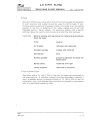
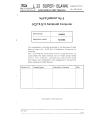
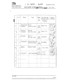
RECORD OF REVISIONS
Any revision or amendment of the present Manual will be issued in the
form of Bulletins, approved by the Civil Aviation Authority of the Czech
Republic, supplement of which will contain new (revised) pages. User's
duty is to make a note about revisions in the Record of revisions and to
replace existing pages with revised and effective ones. Revised or
amended parts of the text will be indicated by a vertical line in the left
hand margin and the revision No . and the date w ill be shown on the
bottom left hand of the page .
Manufacturer's adress : Letecke ZElvody a.s. 686 04 KUNOVICE CZECH REPUBLIC Telephone : + 420-632-81 7650 Fax: + 420-632-81 7653 e-mail: ots@let .cz Rev.
No.
Affected
Section
Affected pages
Date
Bulletin
No.
Date of
Bulletin
approval
1
0, 2,6
0-1, 0-3, 2-3 , 2-4,
6-6
Apr 9/02
L23/043a
Apr 24/02
I
Date inserted and
signature
I
-
Apr 9/02 CD
o- 1
~
L 2 3 S UPER - BLA N IK
68604 KUNOVICE
CZECH REPUBLIC
Rev.
No.
Affected
Section
SAI LPLANE FLI GHT MANUAL
Affected pages
Date
Bulletin
No.
Date of
Bulletin
approval
Do - L 23. 1014.5
Date inserted and
signature
)
}
Jan 4/02
0-2
cs L 23 SUPER - BLANIK
68604 KUNOVICE CZECH REPUBLIC
SAILPLANE FLIGHT MANUAL
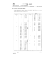
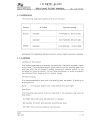
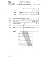
Do - L 23. 1014. 0.2 LIST OF EFFECTIVE PAGES
Pages identified as "Appr." provide information reguired to be furnished
by the Federal Aviation Regulations.
Date
Section
Page
Date
Section
Page
0
1
2
3
4
Apr 9/02
Jan 4/02
Apr 9/02
Jan 4/02
4
Appr. 15
Appr. 16
Appr. 17
Appr. 18
Appr.19
Appr.20
Appr. 21
Appr.22
Jan
Jan
Jan
Jan
Jan
Jan
Jan
Jan
4/02
4/02
4/02
4/02
4/02
4/02
4/02
4/02
1
1
2
3
4
5
Jan
Jan
Jan
Jan
Jan
4/02
4/02
4/02
4/02
4/02
5
Appr. 1
Appr. 2
Appr.3
Appr. 4
Appr.5
Jan
Jan
Jan
Jan
Jan
4/02
4/02
4/02
4/02
4/02
2
Appr. 1
Appr.2
Appr.3
Appr. 4
Appr. 5
Appr. 6
Appr. 7
Appr. 8
Appr. 9
Appr. 10
Appr. 11
Appr. 12
Jan 4/02
Jan 4/02
Apr 9/02
Apr 9/02
Jan 4/02
Jan 4/02
Jan 4/02
Jan 4/02
Jan 4/02
Jan 4/02
Jan 4/02
Jan 4/02
6
1
2
3
Appr. 1
Appr. 2
Appr. 3
Appr. 4
Jan
Jan
Jan
Jan
4/02
4/02
4/02
4/02
7
Appr 1
Appr. 2
Appr. 3
Appr. 4
Appr. 5
Appr. 6
Appr. 7
Appr.8
Appr 9
Appr. 10
Appr. 11
Appr. 12
Appr. 13
Appr.14
Jan
Jan
Jan
Jan
Jan
Jan
Jan
Jan
Jan
Jan
Jan
Jan
Jan
Jan
4/02
4/02
4/02
4/02
4/02
4/02
4/02
4/02 4(02 4/02 4/02 4/02 4102 4/02 8
3
4
Apr 9/02
CD I
4
5
6
7
1
2
Jan 4/02
Jan 4/02
Jan 4/02
Jan 4/02
Jan 4102
Apr 9/02
Jan 4/02
4
5
Jan
Jan
Jan
Jan
Jan
1
2
Jan 4/02
Jan 4/02
1
2
Jan 4102
Jan 4/02
Jan 4(02
3
4/02
4/02
4/02
4/02
4/02
I
I
9
I
3
0-3
~
68604 KUNOVICE CZECH REPUBLIC
L 23 SUPER - BLA NIK
SAILPLANE FLIGHT MANUAL Do - L 23.1014.5
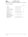
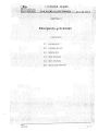
0 .3. TABLE OF CONTENTS
Section
General
( a non-approved section)
1
Limitations
(an approved section)
2
Emergency procedures
(an approved section)
3
Normal procedures
(an approved section)
4
Performance
(a partly approved section).
5
Weight and balance
( a non-approved section)
6
Sailplane and systems description
( a non-approved section)
7
Sailplane handling, care and maintenance
( a non-approved section)
8
Supplements
(a partly approved section)
9
Jan 4/02
0-4
~
686 04 KUNOVICE
CZECH REPUBLIC
L 2 3 SUPER - BLANIK
SAILPLANE FLIGHT MANUAL
Do - L 23. 1014.5
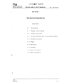
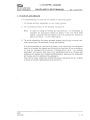
SECTION 1 CONTENTS
\
}
1.1
Introduction
1.2
Certification basis
1.3
Warnings, cautions and notes
1.4
Descriptive data
1.5 .1 Three-view drawing - Dimensions in ft
1.5.2 Three-view drawing - Dimensions in mm
Jan 4/02
1-1
~
L 2 3 SUPER - BLAN IK
68604 KUNOVICE
CZECH REPUBLIC
1.1
SAILPLANE FLIGHT MANUAL
Do - L 23. 1014.5
INTRODUC T ION
The sailplane flight manual has been prepared to provide pilots with
information for the safe and efficient operation of the L 23 SUPER-BLANIK
sailplane. This manual includes the material required to be furnished to
the pilot by JAR - 22. It also contains supplemental data supplied by the
sailplane manufacturer.
1.2
CERTIFICATION BASIS
This type of sailplane has been approved by the Civil Aviation Authority of
the Czech Republic in accordance with JAR-22, Change 4 issued April 1,
1980 including Amendment 22/86/1 Eft. Oct. 22, 1986 and AC 21.17-2.
1.3 WARNINGS, CAUTIONS AND NOTES
The following definitions apply to warnings, cautions and notes used in
the Flight Manual.
WARNING: MEANS THAT THE NON-OBSERVATION OF THE
CORRESPONDING PROCEDURE LEADS TO AN
IMMEDIATE OR IMPORTANT DEGRADATION OF THE
FLIGHT SAFETY
.
CAUTION: means that the non-observation of the corresponding
procedure leads to a minor or to a more or less long
term degradation of the flight safety.
Note: draws the attention on any-special item not directly related
to safety but which is important or unusual.
Jan 4/02 1-2
~
L 23 SUPE R - BLANIK
686 04 KUNOVICE
CZECH REPUBLIC
. 1.4
SAILPLANE FLIGHT MANUAL
Do - L 23. 1014.5
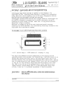
DESCRIPTIVE DATA
The L 23 SUPER - BLANIK sailplane is a cantilever, high-wing, two-seat
glider of all-metal structure. Wing tip extensions are optional.
Basic dimensions
Wing span . . . . . . . . . . . . . . . . . .
(with the installed wing tip extensions)
.53.15 ft (16 .2 m)
.59 .71 ft (1S.2 m)
Note: If the wing tip with supporting
wheel is installed wing span is .
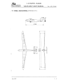
· 53.35 ft (16.26 m) Length
· 27 .S9 ft(S.5 m) Height
.6.23 ft(1 .9 m) Wing area
(with the installed wing tip extensions)
.206.13 sq ft(19.15 sq.m) · 215.27 sq ft(20.00sq.m) Aspect ratio . . . . . . . . . . . . . . . . .
(with the installed wing tip extensions)
· 13 .7 · 16.6 Mean aerodynamic chord . . . . . . . . .
(with the installed wing tip extensions)
· 4.11 ft(1.253 m) · 3.99 ft (1 .21 6 m) )
Jan 4/02
1-3
~
L 23 SUPER - BLANIK
686 04 KUNOVICE
CZECH REPUBLIC
SAILPLANE FLIGHT MANUAL
Do - L 23. 1014.5
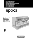
1.5.1 THREE - VIEW DRAWING ( Dimensions in ft)
27.89 0)
O)
0
T"""
T-
LO
I'-
T
ill
(1')
LO LO
I
cR
~
)
\
I
t"-I
v
Jan 4/02
II
\I
1-4
~
L 23 SUPER - BLANIK
686 04 KUNOVICE
CZECH REPUBLIC
SAILPLANE FLIGHT MANUAL
Do - L 23. 1014.5
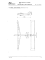
1.S.2THREE· VIEW DRAWING (Dimensions in mm )
8500
,....
rJ.
\
(
00
00
C\JC\J
coc.o
..- ..
\
I
r-l
v
U
II
II
)
Jan 4/02
1-5
~
686 04 KUNOVICE
CZECH REPUBLIC
L 23 SUPER - BLANIK
SAILPLANE FLIGHT MANUAL
Do - L 23. 1014.5
SECTION 2
Limitatio ns
CONTENTS
2.1
Introduction
2.2
Airspeed
2.3
Airspeed indicator markings
2.4
Weight
2.5
Centre of gravity
2 .6
Approved manoeuvres
2 .7
Manoeuvring load factors
2.8
Flight crew
2.9
Kinds of operation
2.10 Minimum equipment
2.11 Aerotow and winch-launching
)
2 .12 Other limitations
2.13 Limitation placards
)
Appr. Jan 4/02
2 - 1
~
L 23 SU PER - BLANI K
68604 KUNOVICE
CZECH REPUBLIC
2.1
SAILPLANE FLIGHT MANUAL
Do - L 23.1014.5
INTRODUCTION
Section 2 includes operating limitations and basic placards necessary for
safe operation of the sailplane, its standard systems and standard
equipment. The limitations in this section are FAA approved by the CAA,
Czech Republic. The values in parentheses are valid only when using wing
tip extensions.
2 . 2 AIRSPEED
Speed
KIAS
(km/h lAS)
Remarks
VNE Never exceed speed up
to a pressure altitude of
13, 780 ft (4200 m)
124
(230)
Do not exceed this speed in any
operation and do not use more
than 1/3 of control deflection
VRA Rough air speed
81
(150) Do not exceed this speed except in
smooth air, and then only with
caution. Examples of rough air are
lee-wave rotor thunderclouds etc.
81
(150) Do not make full or abrupt control
movement above this speed,
because under certain conditions
the sailplane may be overstressed
by full control movement
winchVw Maximum
launching speed
65
(120)
. Do not exceed this speed during
winch- or autotow-Iaunching
Maximum ae rotowin g
speed
81
(150)
Do not exceed this speed during
aerotowing
VLO Maximum landing gear
operating speed
124
(230)
Do not extend or retract the
landing gear above this speed
VA VT Manoeuvring speed
Note: VNE airspeed limits above 13,780 ft (4200 m) Pressure Altitude
are reduced as follows:
Pressure Altitude ft
VNE KIAS
)
*
13,780
20,000
25,000
30,000
35,000
124
(124 )
124
(114 )
116
(105)
108
(97)
100
(89)
*- Altimeter Setting at 29.92 in.Hg (1013 .25 hPa).
Appr. Jan 4(02
2-2 ~
L 23 SUPER· BLANIK
686 04 KUNOVICE
CZECH REPUBLIC
SAILPLANE FLIGHT MANUAL
Pressure Altitude m
*
I
4,200
-
-
VNE km/h lAS
6,000
- _
.
7 ,500
--
230
(210)
230
(230)
Do - L 23.1014.5
9,000
10,500
200
( 180)
185
(165 )
-
215
(195 )
2.3 AIRSPEED INDICATOR MARKINGS
i
Marking
KIAS
(km/h lAS)
Significance
Green arc
36 - 81
(67-150)
Normal Operating Range. (Lower limit is maximum
weight 1.1 VSI at most forward c.g. Upper limit is
rough air speed)
Yellow arc
81 - 124
(150-230)
Manoeuvres must be conducted with caution and
only in smooth air.
-
-
Red line
124
(230)
Yellow
triangle
49
(90)
Maximum speed for all operations
Approach speed at maximum weight.
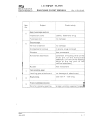
2.4 WEIGHT LIMITS
Maximum take - off and landing weight: 1168 Ib (530 kg) - with two occupants Empty weight with standard equipment
with standard equipment
. 683 Ib ± 2 %(695 Ib ± 2%) or .310 kg ± 2 %(315 kg ± 2%) and the corresponding centre of gravity position
..... .
.67.30 ± 1% MAC(68 .30 ± 1% MAC) Max. weight of all non lifting parts
. 822 Ib (811 Ib) or 373 kg (368 kg) Refer to weight and Balance ( Section 6 .0 ) to determine actual
empty weight / c .g. as established by the installed equipment
and manufacturing tolerances .
Note: ( Cont. )
Appr.
Apr 9/02 CD
2-3
~
L 23 S UP ER - BLANIK
686 04 KUNOVICE
CZECH REPUBLIC
SAILPLANE FLIGHT MANUAL
Do - L 23.1014.5
Pilot's weight (including parachute): - min imum pilot's weight (solo)
. 154 Ib (70 kg) It is necessary to use front seat removable ballast of 33 Ib (15 kg) when flown solo by a pilot (including parachute) weighing less than 154 Ib (70
kg) in the front cockp it.
Note:
Installation of the front seat ballast is described in Section
7, paragraph 7.2 of this Flight Manual.
- maximum pilot's weight ( solo) . . . 287 Ib (130 kg)
Maximum useful load ( occupants,
baggage, optional equipment)
485 Ib (475 Ib) or 220 kg (215 kg)
Maximum baggage compartment load
22 Ib (10 kg)
Appr. Apr 9/02
2-4 ~
L 23 SUPER - BLANIK
68604 KUNOVICE
CZECH REPUBLIC
)
SAILPLANE FLIGHT MANUAL
Do - L 23. 1014.5
2.5 CENTRE OF GRAVITY
Centre of gravity range
- front limit .. . .. . . .
23 % MAC i.e. 4.397 in
(112 mm) aft of
reference datum
- rear limit . . . . . . . . . . . . . . . . . . . . . . 40 % MAC i.e. 12 .783 in
(325 mm) aft of
reference datum
Wing tip extensions installation moves the center of gravity of the empty
sailplane 1 % MAC (0.493 in = 12.53 mm) to the back.
The reference datum is located 93.6 in (2.37 m)aft of the sailplane nose.
2.6 APPROVED MANOEUVRES ( UTILITY CATEGORY)
Sailplane is certified in the Utility Category. With the installed wing tip extensions all aerobatic manoeuvres are prohibited. Procedures Airspeeds - KIAS
Manoeuvre
SOLO DUAL ENTRY RECOVERY )
Loop
86
97
X
Section 4.4.6 item 1. Stall turn
92
97
X
Section 4.4.6 item 2. Lazy Eight
97
97
X
Section 4.4.6 item 3.
Spin 32
86
32
86
X
Chandelle(climbing) 97
97
X
Section 4.4.6 item 5.
Steep turn 92
97
X
Section 4.4.6 item 6.
Appr.
Jan 4/02
Section 4.4.6 item 4.
X
2-5
~
L 23 S UPER - BLANIK
686 04 KUNOVICE
CZECH REPUBLIC
SAILPLANE FLIGHT MANUAL
Do - L 23. 1014.5
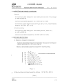
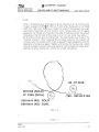
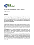
2.7 MANOEUVRING LOAD FACTORS
It is valid for maximum weight of the sailplane.
6
,-...
c
.....
0
......
()
co
'+
I"-
5
r.......
/
4
V
U
co
0
n = + 5.3
....... 3
/
....J
""
/
/
2
t!
/
o
V
:--.
- 1
-2
/
"
185
93
VA
50
~
100
l~ [\
VNE
SPE ED km/h
SPE ED KIAS
lAS
//
1\
......V
'Y
n = - 2.65
-3
FIG. 2 - 1
2.8 FLIGHT CREW
Minimum - one pilot, Maximum number of occupants is two. If the sailplane
is to be flown solo, the pilot must be sitting in the front seat and his weight
(including parachute) must be 154 Ib (70 kg) at least. If the pilot's weight
is less than 154 Ib (70 kg), it is necessary to use the cushion with 33 Ib
(15 kg) ballast.
WARNING: THE REAR SEAT MUST BE SECURED AGAINST FOLDING
AND SAFETY HARNESSES ON THE REAR SEAT MUST BE
CONNECTED, DRAWN TOGETHER AND SECURED.
2.9 KINDS OF OPERATION
The s ai I plane is ap prov'ed for Day VF R operations. Cloud-flyi ng is
permitted where operational regulations permit, and the minimum reguired
eguipment is installed and operable.
( Cant. )
- '
Appr.
Jan 4/02
2-6
L 23 SUPER - BLANIK
~
68604 KUNOVICE
CZECH REPUBLIC
SAILPLANE FLIGHT MANUAL
Do - L 23. 1014.5
WARNING: 1. OPERATIONS IN ICINGCONDITIONSARE PROHIBITED.OPERA
TIONS ARE LIMITED BY THE INSTALLED EQUIPMENT AS
LISTED IN SECTION 6.
2 . AEROBATI C FLIGH T TIME MUST BE RECORDED IN THE
SAILPLANE LOG BOOK TO COMPLY WITH CONTINUED
AIRWORTHINESS REQUIREMENTS.
3. ALL AEROBATIC MANOEUVRES ARE PROHIBITED WITH
INSTALLED WING TIP EXTENSION.
4. WITH INSTALLED WING EXTENSIONS:
ALL FLIGHT TIME WITH WING EXTENSIONS MUST BE
RECORDED IN THE SAILPLANE LOG BOOK TO COMPLY WITH
CONTINUED AIRWORTHINESS REQUIREMENTS.
5. THE NUMBER OF WINCH AND AEROTOW LAUNCHES MUST BE
RECORDED IN THE SAILPLANE LOG BOOK TO COMPLY WITH
CONTINUED AIRWORTHINESS REQUIREMENTS.
2.10MINIMUM EQUIPMENT
Instruments and minimum equipment must be approved types.
A. Instruments All Operations: - Airspeed indicator - Altimeter - Lap and shoulder straps B. Additional Instruments required for Cloud flying: - Magnetic compass - Turn and bank indicator - Variometer(Vertical Speed Indicator) Appr.
Jan 4/02
2-7
L 23 SUP ER - BLANIK
~
686 04 KUNOVICE
CZECH REPUBLIC
SAILPLANE FLIGHT MANUAL
Do - L 23. 1014.5
2.11 AEROTOW AND WINCH LAUNCHING
Aerotow
- the maximum cable strength or cable safety device (weak link) strength
is 1460 Ib (6500 N).
- maximum permissible speed VT
= 81 KIAS (150 kmlh lAS)
- the minimum cable length for aerotowing is 50 ft (15 m), recommended
length is 100-130 ft (30 - 40 m).
Winch-launching
- the maximum cable strength or cable safety device ( weak link)
is 1460 Ib (6500 N).
- maximum permissible speed Vw = 65 KIAS (120 km/h lAS)
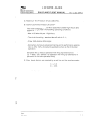
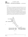
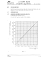
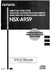
2.120THER LIMITATIONS
A. Maximum crosswind component
- maximum demonstrated crosswind component for safe approach, landing and
aerotow launching is 16 kt (8 m/s) for angle 90 0 .
Maximum demonstrated crosswind component for winch-launching:
e
24 kI
Ql 221ct
a
c.
E
a
20 Ict
c
()
"C c
RELATIVE ANGLE TO WIND DIRECTION
18 Ict
10 let
a....
6 k1
0
10'
16 let
14 Ict 12 let
~
en
o·
8 k1
80'
4 kt
2 kI
90'
FIG. 2 - 2
B.Maximum demonstrated operating altitude - 13, 780 ft (4,200 m)
( Cont. )
Appr.
Jan 4/02
2-8
~
L 2 3 SUPER - BLANIK
68604 KUNOVICE
CZECH REPUBLIC
SAILPLANE FLIGHT MANUAL
Do - L 23. 1014.5
C. Maximum Tire Pressure 37 psi (250 kPa).
D. Continued Airworthiness Life Limits:
The initial sailplane service life is specified to 6000 flight hours and 30000 landings under the following operating conditions: - Max. 4.83 take-ofts per 1 flight hour; - The winch launching - aerotow take-off ratio is 5 : 1; - Crew: 35% double, 65% single; - Elementary training-to-advanced training and to performance soaring ratio is 40% : 60%, whereby the aerobatics share is 2% of the total
operation .
Sailplane life LB versus operation with wing tip extensions is
LB = 6000 - 25 .x (where x is operation with wing tip extensions in
percents of the total operation time)
E. M ax. loads factors are marked by a red line on the a.ccelerometer:
n == + 5 .3
n ==- 2.65
)
)
Appr.
.I;:,n t1/n')
;J . g
~
L 2 3 SUPER - BLANI K
68604 KUNOVIC E
CZECH REPUBLIC
SAILPLANE FLIGHT MANUAL
Do - L 23. 1014.5
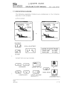
2.13L1MITATIONS PLACARDS
The following operat i ng limitations are emphasized on the limitation
placards in bo th cockp its:
a) front cockpi t
o
o
0
0
MIN. PILOT'S WEIGHT FOR SOLO FLIGHTS:
- WITHOUT BALLAST
.1 54 LB
121 LB
- WITH 33 Ib BALLAST
MIN. PILOT'S WEIGHT FOR SOLO FLIGHTS:
70 kg
- WITHOUT BALLAST
- WITH 15 kg BALLAST
55 kg
or
)
o
o
o
o
SEAT BACK
PEDAL ADJUSTMENT
CENTRE OF GRAVITY RANGE
FRONT LIMIT
23 % MAC
REAR LIMIT . . 40 % MAC
AIR VENT
b) both front and rear cockpits
r
\
'\
l~)
r
,
l~~)
AIR BRAKES
(e=C)
(~)
LANDING GEAR
CANOPY LIFT OFF
( 2=')
CANOPY JETTISON
see para 3.2.2
or
(~)
WHEEL BRAKE
BAGGAGE
(REAR SEAT ONLY)
Appr.
Jan 4/02
2 - 10
~
L 2 3 SUPER - BLANI K
686 04 KUNOVICE
CZECH REPUBLIC
SAILPLANE FLIGHT MANUAL
00 - L 23 . 1014.5
On customer'S request:
MAX. ALLOWABLE SPEED VS ALTITUOE '.
PRESSURE ALTITUDE (FT) UP TO
WITHOUT EXTENSIONS
WITH EXTENSIONS
13 780 20 000 25 000 30 000 35 000 124
124
116
108
100 124
114
105
97
89 or
MAX. ALLOWABLE SPEED (km/h lAS) VS ALTITUDE
PRESSURE ALTITUDE (m) UP TO 4200
WITHOUT EXTENSIONS
230
WITH EXTENSIONS
230
6000
7500
215
195
230
210
9000
200
180
10500 185 165 If installed wing tip extensions:
ALL AEROBATIC MANOEUVRES ARE PROHIBITED WITH INSTALLED WING TIP EXTENSIONS TRIMMER
RELEASE
V NE
124 KIAS
V RA
81-KIAS . . " .
or
V NE
230 km/h lAS V RA
150 km/h lAS Valid when lower or side hook is installed :
)
MAX. WINCH - LAUNCHING SPEED
MAX. AERO - TOWING SPEED
MAX. MANOEUVRING SPEED
65 KIAS
MAX. WINCH - LAUNCHING SPEED
81 KIAS or MAX. AERO - TOWING SPEED
81 KIAS
MAX. MANOEUVRING SPEED
120 km/h lAS
150 km/h lAS
150 km/h lAS
Val id when iront hook only is installed :
MAX. AERO - TOWING SPEED
81 KIAS
MAX. MANOEUVRING SPEED
81 KIAS
or
MAX. AERO - TOWING SPEED
150 km/h lAS
MAX. MANOEUVRING SPEED
150 kmi h lAS
)
Appr.
;J
11
L 23 SU PER· BLANIK 686 04 KUNOVIC E
CZECH REPUBLIC
SAILPLANE FLIGHT MANUAL
Do - L 23. 1014.5
OPERATING LIM ITATIONS
T HI S GLIDER MUST BE OPERATED
IN COMPLIANCE WITH THE OPERATING
LIMITATIONS STATED IN THE FORM
OF PLACARDS, MARKINGS AND MANUALS
MAX. GROSS WEIGHT
1168 LB
APPROVED MANOEUVRES:
LOOP
SPIN
STALL TURN
CHANDELLE(CLIMBING)
LAZY EIGHT
STEEP TURN
SOLO FLIGHT FROM FRONT SEAT ONLY
or
OPERATING LIMITATIONS
THIS GLIDER MUST BE OPERATED
IN COMPLIANCE WITH THE OPERATING
LIMITATIONS STATED IN THE FORM
OF PLACARDS, MARKINGS AND MANUALS
530 kg
MAX. GROSS WEIGHT
APPROVED MANOEUVRES:
LOOP
SPIN
CHANDELLE(CLIMBING)
STALL TURN
LAZV EIGHT
STEEP TURN
SOLO FLIGHT FROM FRONT SEAT ONLY
c) exterior markings
Near the static pressure sensor.
( STAT)
Appr.
Jan 4/02
2 - 12
;
,".>
'\ :
., .~
.,'"
., ',':.
-'
-.
~
68604 KUNOVICE
CZECH REPUBLIC
L 23 SUP ER - BLANIK
SAILPLANE FLIGHT MANUAL
Do - L 23. 1014.5
SECTION 4
Nor mal pro ce dure s
CONTENTS
4.1
Introduction
4.2
Rigging and de-rigging
4.3
Pre"flight Inspection
4.4
Normal operations and recommended speeds
4.4.1 Take-off and climb
4.4.2 Flight
4.4.3 Approach
4.4.4 Landing
4.4.5 Use of air brakes
4.4.6 Basic aerobatics
Appr. Jan 4/02
4 - 1
~
L 23 SUPER - BLANIK
68604 KUNOVICE · CZECH REPUBLIC
4.1
SAILPLANE FLIGHT MANUAL
Do - L 23. 1014.5 INTROD UCTION
Section 4 provides checklists and information on recommended ·
procedures for normal operation .
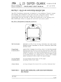
4 .2
RIGGI NG AN D D E-RI GG I N G
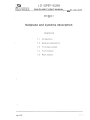
A.Wing removal
Four people are needed for the wing removal. The first holds the
fuselage, the second holds the wing tip , the third and the fourth hold the
wing root (see Fig . 4-0). Level the sailplane to the horizontal position.
Take off the fairings between the fuselage and the wing. Uncouple the
aileron control tie rods by unlocking safety pins and removing pins on
rocker levers, pivoted in consoles on the ribs No.1 (from the fuselage
side). Remove lock pins out of both front hinge pins and wing main pins
and knock out the front pin. Remove eletrical ground strap.
Move the wing gently up and down when installing or removing the pins .
Pull the wing from the fuselage by slow careful movement and sit the
wing vertica lly with the leading edge down on the special handling
equipment.
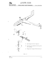
B.Wing installation
The process of wing installation is the opposite. For easier installation
of the centre hinge pins use the centering pin (or installation drift
pin)before inserting the main pins (see Fig. 4-0, Detail A). When slipping
wing hinges on fuselage hinges make sure that the globular joint of the
air brakes control (see Fig. 4-0 , Detail B) will be pOSitioned to fit into the
control dr ivers in the wing .
When assembling first slide in the wing main hinge pin and then the wing
front hinge pin.
CHemoval and installation of the wing tip extensions
Remove 12 bolts at the last wing rib fixing the wing tip and remove the
wing tip and/or wing tip extension.
Perform the installation in the reverse oder. Insert the extension and/or
by its guiding into the guiding tube at the last wing rib ,adjust it in the
proper position and fix with original bolts (10 pieces of M4 sunk bolt and
2 pieces of M5 fitted bolt with cylinder head) at both the wing
ends.Tighten all the screws and bolts.
( Cont. )
Appr. Jan 4(02
4 -2
~
686 04 KUNOVICE
CZECH REPUBLIC
L 23 SUPER - BLANIK
SAILPLANE FLIGHT MANUAL
Do - L 23. 1014.5
@
B
\
J
A - Centering the front hinge pin
B - Control joint between the wing and
the fuselage
C - Wing main hinges with the main pin
FIG. 4 - 0
Appr. Jan 4/02
4-3 L 23 SUPER - BLANIK
~
68604 KUNOVICE
CZECH REPUBLIC
SAILPLANE FLIGHT MANUAL
Do - L 23. 1014.5
D .H 0 r i Z 0 n t a 1st a b iii z e r ins t a II at ion
The process of horizontal stabilizer installation is the opposite . It is
recommended that the ho r izontal stabilizer and the automatic
connection rocker levers of the elevator trim tab control on the vertical
stabil izer , and on the horizontal stabilizer , are approximatelly parallel.
E.Horizontal stabil izer removal
Remove the safety wire from the front pin of the horizontal stabilizers (in
front of the leading edge of the vertical stabilizer on its top) . Rotate t he ·
pin handle 180° and pull out the pin . Elevate the horizontal stabilizer
leading edge about 30° up, slip out the horizontal stabilizers from pins
by pulling forward. It is recommended that the elevator to be in the
neutral position during removal. Put the horizontal stabilizers on the
special handling equipment support.
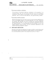
4.3
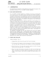
PREFLIGHT INSPECTION
The pilot must check the sailplane for proper condition in accordance with
the checklist walkaround inspection (before getting into the sailplane) .
It is recommended to perform the inspection as show in Fig.4-1 .
)
Appr. Jan 4/02
4-4 ~
68604 KUNOVICE
CZECH REPUBLIC
L 2 3 SUPER · BLANIK
SAILPLANE FLIGHT MANUAL
Do - L 23. 1014.5
Sequence of the walkaround inspection
1""-"\
~
\
'\
__ ®--c-,
t'
I
(
I
f
I
I
I
I
y
I
~
)
I
~-c>-) !
I
I
I
I
~
r
?,
I
I
I
f
J
I
/
\
\
\
~
I/ I
'--
I
FIG. 4 - 1
( Cant. )
Appr. Jan 4/02
4-5 L 23 SU P ER - BLANIK
~
686 04 KUNOVICE
CZECH REPUBLIC
SAILPLANE FLIGHT MANUAL
Do - L 23. 1014.5
4.3 . 1 WALKAROUND INSPECTION CHECKLIST
Item No. 1
2
Check/activity
Subject
Front fuselage section
Fuselage skin
no damage
Left & right static probes
ports clear
Cockpit canopy surface
no damage or dirt
Nose pitot tube
no damage or clogging
Cockgit
Instruments
nodamage
Altimeters
correct setting OFE (ON H)
Radio station (if installed)
proper operation
Front ventilation
for season
f-
Safety belts
3
no damage
Landing gear
Tire
4
no damage, correct inflation
Left wing
Wing skin including leading no damage
edge
Wing-tip fairing
(wing tip extension)
no damage or loose
Aileron skin
Ino damage to fabric cover or
trailing edge
Ailerons
free movement
Airbrake locking
~inges
locking no damage of hinges or
control tie rods
( Cant. )
Appr.
Jan 4/02
4-6
~
L 23 SU PE R - BLANIK
68604 KUNOVIC E
CZECH REPUBLIC
SAILPLANE FLIGHT MANUAL
Item
No.
5
6
7
8
)
9
Subject
Do - L 23. 1014.5
Check/ activity
Rear fuselage section
Ins p ection ports
cables , fasteners snug
Fuselage skin
no damage
Emgennage
Vertical stabilizer
no damage
Compensator pickup
in place, plug removed
Elevator
free movement
Horizontal stabilizers
condition of locking wire on the
fro n t pin of th e horizontal
stabilizer (in front of the leading
edge of th e to p part of the
vertical stabilizer)
Rudder
free movement
Tail landing gear
Landing gear attachment
no damage of attachment
Right wing
see Item 4 - left wing
Front fuselage section
Pins for canopy opening
proper position against hinges
~------------------------------~--------------------~------------
Appr. Jan 4/02
4-7 L 23 SUPE R - BLANIK
~
68604 KUNOVICE
CZECH REPUBLIC
SAILPLANE FLIGHT MANUAL
Do - L 23. 1014.5
4.3.2BEFORE TAKE-OFF CHECKLIST
Front seat
Before entering the front cockpit, adjust the front seat back-rest to a
position allowing control of the sailplane when fully strapped in.
Rudder control
The posit io n of the rudder pedals should be adjusted with the pilot fully
strapped in so th at both left and right pedals can be moved comfortably
to the full extent of their travel. The position of the rudder pedals in the
front cockpit can be adjusted by means of the crank. In the rear cockpit,
adjustment to one of three possible positions may be obtained by
removing the locking pin.
Note: This can be done only before the flight. Control column Check for full and free movement of the control column in all directions; move it to the left, to the right, forwards and backwards. Instruments Set the altimeters to zero or as desired by the baro-set knob. Check the other instruments and see that vertical speed indicators and airspeed
indicators read zero .
Cockpit canopy
Close and lock.
Safety belts
)
Fasten the safety belts. Set the elevator trim tab to the neutral position marked "0" . Air brakes Check for easy movement of air brake control. Confirm air brakes retracted for take off. Tow rope release Check the tow rope release mechanism for proper functioning. Appr. Jan 4/02
4-8 L 23 SUPER - BLANIK
~
68604 KUNOVICE
CZECH REPUBLIC ·
4 .4
SAILPLANE FLIGHT MANUAL
Do - L 23. 1014.5
NORMAL OPERATIONS AND RECOMMENDED SPEEDS
4. 4. 1TAK E-OF F AN D C LIM B
1.Aerotow launching
T he take-off technique by aero tow is entirely conventional. The elevator
and rudder efficiency is high enough during the initial stages of the
t ake-off run, that it is easy to prevent directional or roll oscillations by
use of rudder or ailerons, Set the elevator trim tab control to a position
between "zero" and "nose heavy " and hold the control stick in the neutral
position - on the landing gear and at liftoff speed pull the control stick
gently to unstick the sailplane. Hold the sailplane in horizontal flight at
a height of 3 ft (1 m) until the towing airplane starts to climb . The take-off
with cross wind is different from the normal take-off. It is necessary to
bank the wing into the wind ( in proportion to the wind speed) and to
unstick t he sailplane at a higher speed. The tow rope should be attached
to the front hook only.
Note: Before take-off close the ventilation in order that dust and
impurities do not get into the cockpit. The ventilation can be
opened during at climb.
2.Winch-launching
CAUTION: Use either side hooks or lower hook (depending on
which hook is installed).
WARNING: NEVER USE FRONT HOOK FOR WINCH-LAUNCHING.
The winch
control to
lauching is
gear when
launching is entirely conventional. Set the elevator trim tab
the neutral position. The recommended speed for winch
43 - 54 KIAS (80 - 100 km/h lAS). Do not retract the landing
performing the traffic pattern .
3.Aerotow
a)Climb
Retract and lock the landing gear (by pulling the handle in your
direction) when above ami n imum safe height of 66 ft and the m inimum
speed of 54 KIAS (100 km/h lAS) is reached. Trim the sailplane for the
clim speed . The sailplane angle of attack is fairly high when the climb
speed is low and the' view from cockpit is reduced considerably.
Therefore it is recommended that the towing aircraft to keep a climbing
speed of 54 - 70 KIAS (100 - 130 km/h lAS)
( Cont. )
Appr. Jan 4/02
4-9 L 23 SUPER - BLANIK
~
686 04 KUNOVICE
CZECH REPUBLIC
SAILPLANE FLIGHT MANUAL
Do - L 23. 1014.5
) T he pilot should avoid overcontrolling.
I
PrinCiples of aerotow are the same as for other sailplanes.
b )Level flight
The maximum speed for aerotow is 81 KIAS (150 km/h lAS). It is
necessary to trim the sailplane to reduce control forces and to decrea
se pilot fatigue during longer flights on tow. It is necessary to realize
that control sen si tivity increases with flight speed.
c)Oescend i ng
A satisfactory rate of descent 390 - 590 ft/min (2 - 3 m/s) can be
obtained when the towing aircraft maintains an airspeed at least of
54 KIAS (100 km/h lAS) .
)
Appr. Jan 4/02
4 - 10 L 23 SUPER - BLAN IK
LS
686 04 KUNOVICE
CZECH REPUBLIC
SAILPLANE FLIGHT MANUAL
Do - L 23. 1014.5
\ 4.4.2 FLIGHT
J
1.Turns an d circling
The sailplane is very manoeuvreable and controllable and its behaviour
is very good in t urn s wit h angles bank up to 60°,
2.Side slippi n g
The piloting technique of the si de slipping is entirely conventional. The
angle of bank of the sailplane should be between 10° and 20° .The side
slip is not very effective mean of loosing height in this sailplane. As, the
rate of descent may be effectively increased by the use of the air brakes.
If a constant airspeed is to be maintained during a side slip, the angle
of pitch must be constant. The air speed indicator is unreliable during
slip manoeuvers.
43 KIAS
(80 km/h lAS)
I
:
FIG. 4 - 2
)
Appr. Jan 4/02
4 - 11 ~
L 2 3 SU PER - BLANI K
68604 KUNOVICE
CZECH REPUBLIC
SAILPLANE FLIGHT MANUAL
Do - L 23. 1014.5
3.Stalls
Slow and continuous pulling aft on the control stick causes the sailplane
to stall. Ailerons and rudder should be used to control bank, if any.
Pre-stall warning starts (at the speed of about 5% higher than the stalling
speed) , in the form of buffeting of the rudder pedals and of all front
f uselage section. When stalled, the sailplane settles with a gentle
pitching . M ave the contro.1 stick forward and start the stall recovery.
CAUTION: Before stalling and spinning the following procedures
must be done:
Trim: neutral
Air brakes: retracted and secured
Cockpit canopy locked and secured
Ventilation shut
Rudder pedals: properly adjusted to allow full
deflections
Safety belts: fastened and tight
Loose objects: removed or secured
4.High Altitude Flight
)
Operation above 13, 780 (4,200 m) feet has not been demonstrated by
the manufacturer. A sailplane placard provides calculated maximum (
VNE) airspeeds above a pressure altitude of 13, 780(4,200 m) feet for
information only. High altitude fli g ht should be conducted in accordance
with any applicable operating rul e s .
Appr. Jan 4/02
4 - 12 L 23 SUPER - BLANIK
~
68604 KUNOVICE
CZECH REPUBLIC
SAILPLANE FLIGHT MANUAL
Do - L 23. 1014.5
\ 4 .4.3APPROACH
I
The following approach speeds are recommended.
Descent
Normal
Steeper
Air brakes
Approach speeds
retracted
41-46 KIAS (75 - 85 km/h lAS)
extended
43-51 KIAS (80 - 95 km/h lAS)
extended
51-60 KIAS (95 - 110 km/h lAS)
Anticipate mild sailplane ballooning when using higher approach speeds.
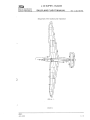
4.4.4 LANDING
Landing on the airport
The landing manoeuvre is entirely conventional. Use small elevator inputs
at the flare . The sailplane should touch down with the landing gear first
and then with the tail wheel if landed correctly(to reduce shock to the
tail wheel on ground contact). Do not flare prematurely in order to prevent
the sailplane from droping from a higher height.
Off-field landing
It is recommended to land with the landing gear retracted if landing on
a soft ground.
Note:
In this case extend the wheel before the next flight.
Post flight
The following operations must be recorded in the sailplane tog book as
they occur:
(1) Flight time with wing tip extensions installed.
(2) Number of winch and aerotow launches by type.
(3) Flight time during acrobatic manoeuvers.
Appr. Jan 4/02
4 - 13 ~
L 23 SUPE R - BLA NI K
68604 KUNOVICE
CZECH REPUBLIC
SA ILPLANE FLIGHT MANUAL
Do - L 23. 1014.5
4.4.5 USE OF AI R BRAKES
It is recommended to use the air brakes in following cases:
1. T o reduce landing especially roll on rough ground.
2 . To increa se a c curacy of the landing manoeuvre.
Note : In case of using air brakes during landing , It IS necessary to
maintain an approach speed of about 5 kts (10 km/h lAS)
higher, because the stall speed with fully opened air brakes is
about 3-4 kts(5 - 7 km/h lAS) higher.
3.To avoid exceeding the never exceed speed (vNE)during unusual atti
tude recoveries (for example during aerobatics).
It is recomme n d e d to use the air brakes in any case when the sailplane
starts to increase the speed and the pilot is uncertain of his orientation
or how to manage the situation. Configuration with" air brakes
extended" will ensure that VNE is not exceeded. Use of air brakes will
enhance the safety and makes handling easier because the extended
air brakes tend to stabilize the sailplane.
The control lever should be held firmly when operating the air brakes
to ensure smooth deployment and retraction.
Appr. Jan 4/02
4 - 14 ~
686 04 KU NOVICE
CZECH REPUBLIC
L 23 SU PER - BLAN IK
SAILPLANE FLIG HT MANUAL
Do - L 23. 1014.5
) 4.4.6BASIC AEROBATICS The L 23 SUPER-BLANIK sailplane is able to perform the listed approved
aerobatic manoeuvres. The rate of acceleration of this sailplane is high,
so great care must be taken not to exceed limitations given in Sections
2.2 , 2.6 and 2.7. Instruction g uidelines for performing approved aerobatic manoeuvres are
given on pages 13 to 19 of this Section. WARNI NG : ONL Y MANOEUVRES WI T H POSITIVE G LOAD FACTORS
ARE APPROVED.
)
)
( Cont. )
Appr. Jan 4/02
4 - 15 ~
L 23 SUPER - BLANIK
68604 KUNOVICE
CZECH REPUBLIC
SAILPLANE FLIGHT MANUAL
Do - L 23. 1014.5
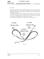
1.Loop
Enter a moderate dive with slight forward movement of the control stick
to gain a speed o f 86 KI AS (160 km/h lAS) when flying solo or 97 KIAS
(180 km/h lAS) when flying dual. Ra ise the nose of the sailplane by slight
backward movement of the control stick, taking care not to apply
excessive "g" forces, and maintain this rate of backward stick movement
throughout the first half of the loop, but do not use more than about
60 % of the control stick full deflection. The load factor must drop in the
inverted position. After passing the inverted position the speed will
increase and the control stick must be eased forward gradually until the
sailplane is flying level again. Before and during this manoeuvre rudder
should be used to prevent yaw and ailerons used to keep the wings level.
Maintain precise directional control for proper completion.
\
86 KIAS (SOLO)
97 KIAS (DUAL)
86 - 97 KIAS
"
6
®
~~~-
(160 - 180 km/h lAS
(160 km/h lAS) - SOLO
(180 km/h lAS) - DUAL
FIG. 4 - 3
( Cont. )
Appr. Jan 4/02
4 - 16 ~
L 23 SUPER - BLANIK
68604 KUNOVICE
CZECH REPUBLIC
SAILPLANE FLIGHT MANUAL
Do - L 23. 1014.5
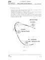
2.Stall turn
This manoeuvre should be begun at the speed of 92 KIAS (170 km/h lAS)
when flying solo or 97 KIAS(180 km/h lAS) when flying dual. Pull the
control stick gently backward to bring the nose to a position of about
60 0 to 70 0 above the horizon. Ease the control stick forward slightly to
maintain this attitude. As the speed falls to 70 - 76 KIAS (130 - 140 km/h
lAS), start to apply rudder slowly in the required direction of turn. As the
force on the rudder decreases, gradually apply full rudder.
Full deflection of the rudder should be reached when the sailplane heads
about 45° in the direction of turn. The ailerons should be used against
the direction of turn as necessary to prevent the sailplane rolling to the
inverted position. As the nose approaches the reciprocal heading,
neutralize the rudder, keep the wings level by use of the ailerons, and
ease out of the resulting dive, taking care not to apply excessive "g".
70 - 76 KIAS
®
(130 - 140 km/h lAS) .~
<\<:J
C:)
<0
~~
(170 kmih jA~) - SOLO
(180 km/h lAS) - DUAL
~ 92
KIAS (SOLO)
~ 97 KIAS ( DUAL)
FIG. 4 - 4
( Cont. )
Appr. Jan 4/02
4 - 17 L 23 SUPER - BLANIK
~
68604 KUN OVI C E
CZECH REPUBLIC
SA I LPLAN E FLIG HT MAN UAL
Do - L 23. 1014.5
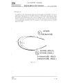
3 . Lazy eight
Move the control stick slowly forward to attain the entry speed of 97 KIAS
(180 km/h lAS) solo or dual. Perform the steep turn to the selected side,
smoothly pulling the control stick with simultaneous coordinated use of
ailerons and rudder.
At a speed of 54 KIAS (100 km/h lAS) transition the sailplane to a descent
a nd after reachin 9 a speed of 97 KIAS (180 km/h lAS perform the steep
turn to the opposite side, smoothly pulling the control stick with
simultaneous coordinated use of ailerons and rudder.
The flight path intersects at the lowest point of the manoeuvre.
97 KIAS
54 KIAS
(100 km/h lAS)
(180 km/h lAS) /
97 KIAS
®~
(180 km/h lAS)
FIG . 4 - 5 \,J
Appr. Jan 4/02
4 - 18 ~
L 23 SUPER - BLANIK
68604 KU NOVICE
CZECH REPUB LIC
SAI LPLANE FLI GHT MAN UAL
Do - L 23. 1014.5
4.Spin
T he sailpl an e performs the spin without any tendency t o enter a flat spin
at all operat i ng centre of gravity positions. The sailplane has the
tendency to recover from the spin by itself, when at the maximum flight
weight and the forward centre of gravity. Entering the spin is entirely
conventional. Pull the control stick slowly back to approach the stall, use
the full deflection of the rudder at the stall speed of aproximately 32 KIAS
(60 km/h lAS) (Fig . 4-3) and maintain full aft deflection of the control
stick . Initiate recovery from the spin by applying full opposite deflection
of the rudder . When the sailplane stops the rotation, neutralize the
rudder and Simultaneously ease the control stick forward. Recover the
sailplane from the dive in the usual way. The attitude during the spin is
60 0 to 70 0 nose down and the loss of height in one turn is aproximately
260 ft (80 m ) when flying solo and 390 ft (120 m) when flying dual. The
time of one revolution of the spin is approximately 3.5 secs.
Caution: 1. Before spinning accomplish the procedures given in
the Flight Manual, Section 4, paragraph 3.
2. lAS error.
The airspeed indications become erroneous at large
yaw angles, because the static vents on the sides of the
fuselage are by-passed asymetrically.
3. When the spin is performed as an aerobatic manoeuvre,
it is possible to maintain the spin by applying aileron
in the direction of the rotation.
Stop the spin rotation by applying full opposite rudder
and neutralize the ailerons. When the sailplane stops
the rotation, neutralize the rudder and ease the control
stick forward. Pull-out from the dive using standard
procedure.
Note: Airspeed indications well above the stall speed during a spin
may indicate a spiral dive rather than a spin.
J
( Cant. )
Appr. Jan 4/02
4 - 19 ~
68604 KUN OVICE
CZECH REPUBLIC
L 23 SUPER - BLANIK
SAILPLANE FLIGHT MANUAL
®
Do - L 23. 1014.5
32KIAS
(60 km/h lAS)
,~
))
,
-~®
43 - 54 KIAS
(80 - 100 km/h lAS)
)
(150 - 160 km/h lAS)
)
Appr. Jan 4/02
FIG. 4 - 6
4 - 20 ~
L 23 SUPER - BLAN I K
686 04 KUNOVICE
CZECH REPUBLIC
SAILPLAN E FLI GHT MAN UA L
Do - L 23. 1014.5
5.Chandelle (climbing)
Move the control stick slowly forward to attain the entry speed of 97 to
103 KIAS (180 to 190 km/h lAS) solo or dual .
Transition the sailplane to a steep climb at an angle of approximately
45° above the horizon (do not increase the angle).
At a speed of 76 KIAS (140 km/h lAS), apply the rudder to the selected
side of the turn and by coordinated positive use of the ailerons make a
transition t o gliding flight in the opposite direction at a minimum speed
of 43 KIA S (80 km/h lAS).
.®
~ .
76 KIAS
(140 km/h lAS)
97 - 103 KIAS
@(180 -190 km/h lAS)
....
.
~--"
FIG. 4 - 7
( Cont. )
)
Appr. Jan 4/02
4 - 21 L 23 S UP ER - BLAN IK
~
686 04 KUNOVICE
CZECH REPUBLIC
SA I LPLA NE FLI GHT MANUAL
Do - L 23. 1014.5
6. Steep turn
To perform this manoeuvre keep the entry speed of 92 KIAS (170 km/h
lAS) when flying solo or 97 KIAS (180 km/h lAS) when flying dual. Enter
the climb s i multaneously with a b ank of approx. 45°. After turning 150 0
start a transition to a glide angle such that the manoeuvre will be finished
in the opposite direction with t h e speed not decreasing below 43 KIAS
(80 km/h lAS).
CZ\
43 KIAS
~(80 km/h lAS)
~'---
~/
----.~--...~ 92 KIAS ( SOLO)
~
97 KIAS ( DUAL)
(170 km/h lAS) - SOLO
(180 km/h lAS) - DUAL)
FIG. 4 - 8
Appr. Jan 4/02
4 - 22 ~
68604 KUNOVICE
CZEC H REPUBLIC
L 23 SUP ER - BLANIK
SAI LPLA NE FLI GHT MANUAL
Do - L 23. 1014.5
SEC T ION 5
Perf o rmance
CONTENTS
5.1
Introduction
5 .2
Approved data
5.2.1 Airspeed system calibration
5.2 .2 Stall speeds
5.3
Additional information
5.3.1 Flight polar
)
Appr. Jan 4/02
5 -1
L 23 SUPER - BLANIK
~
68604 KUNOVICE
CZECH REPUBLIC
SAI LPLAN E FLIG HT MANUAL
Do - L 23. 1014.5
IN T ROD U C TI ON
Section 5 provides approved data for airspeed calibration and stall
speeds. Other non-approved information is provided.
5.2
APPROVED DATA
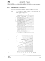
5.2 .1
AIRSPEED INDICATOR SYSTEM CALIBRATION.
( Assumes zero instrument error)
It is valid for maximum weight of the sailplane.
(/)
<{
150
280
.
(/)0
or
<{.c
140
~~
130
0--
I
"'0
Q)
Q)
0.
<{
"'0
-co
Q)
'/
240
120
110
200
~
100
90
'
80
co
70
160
.Q
0
V
120
60
V
50
40
f-?'
80
....-:V
r
r
V
V'
'I'
~-
r
~
'I
V
"
r/
"
ll"
30
20
1/
~
I
III
'
1/
V
40
10
/
0
V'
I
80
40
0
120
200
160
I
I
I
I
I
I
I
I
0
10
20
30
40
I
50
60
70
80
I
I
I
280
240
I
I
I
I
90 100 110 120 130 140 150
Flight speed - km/h lAS
- KIAS
)
Appr.
Jan 4/02
FIG. 5 - 1
5-2
~
L 23 SUPER - BLANIK
686 04 KUNOVICE
CZECH REPUBLIC
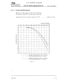
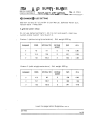
p. 2 .2
SA ILPLANE FLI GH T MANUAL
Do - L 23. 1014.5
STAL L SPEED S ( unacc e lerated )
The broken line is valid only when using the wing tip extensions.
Note: The stall warning speed is about 5 % higher than stall
speed for all configurations.
Stall speed for forward c.g. position
35
air brakes extended
I
CfJ <{ ;::
V
\
~
(j) Q) ,.-
0. (f)
ro
30 en
-I--"
- -
.---V
--- - --
\
\ f-
--
.--
-
.---
~~.
-
I-
I
.--
25
:..--
V
---
..
l--':' V .-
-----
/
~
V
.--
~
....)-f-"'" --
:..--- V
-
f
~-
-' -
-
_f
..-
,
air brakes retracted
,
I
I
20 1000
900
1100
Weight Ib
70
Cf)
~
..c
E
V
.:i:. air brakes extended
"0 ---+- "'"
<l) <l)
0. If)
60
--t---r ro
US
V
V
V air brakes retracted..-- V
V_
~ V ~
50
V- I--
\ ......
-- --
I
40
380
----
.---
400
420
440
-
- -
460
V V
~
-::::
~ k::
f-
--- --
---
- -- -"
r---
.-v'
-
.....
480
500
520
Weight kg
FIG. 5 - 2
Appr. Jan 4/02
5-3 ~
L 23 SUPER - BLANIK
686 04 KUNOVICE
CZECH REPUBLIC
) 5 .3
SAI LPLANE FLIGHT MAN UAL
Do - L 23. 1014.5
ADD IT IONA L I NFOR M ATI ON
5.3. 1
FLIGHT POLAR
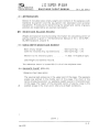
5.3. 1.1
FLIGHT SPEED POLAR
Maximum flight weight of 882 Ib and 1168 lb. Air brakes retracted, landing gear retracted, Airspeed w ith the angle of descent of 45°
. , . . . . . . . 124 KIAS Airspeed
00
-200
-400
<::
-a::
10
20
30
40
...... ....
-
50
60
Ri
'"
;::.
,
100
110
120
KIAS
130
140
~"""",
,,'"
.~
-600
~
.~
."
"\"
-800 .\
~
~
.\. ~
'\. ~
"\ "\.
-1000
u
:.e
90
I
:;:, 0
80
~r---.....
.~ ..,'"
70
-1200
'~
~\
.\
-1400
'\.
.\
''!I,.
,
.\
-1600
.\
,
l .\
-1800
-2000
1\
..~
-2200
L 23 without wingtip extensions, m = 1168 Ib
L 23 with wingtip extensions, rn = 1168 Ib
=
L 23 without wingtip extensions, m
882 Ib
L 23 with vvingtip extensions, m
8S2 Ib
=
FIG. 5 - 3
Jan 4/02
5-4
~
L 23 SUPER - BLAN IK
686 04 KU NOVICE
CZECH REPUBLIC
SAILPLANE FLIGHT MANUAL
Do - L 23. 1014.5
5. 3 . 1.2 F LIG HT SPEE D POLAR
Maximum flight weight of 400 kg and 530 kg. Air brakes retracted, landing gear retracted. Airspeed with the angle of descent of 45°
............... 229 km/h lAS Airspeed lAS (kmfh)
o
0
20
40
60
80
I~'
-1
-2
-3
100
120
140
~ ~
240
~
'\ ~\
~ -6
'\ '\
III
-7
'\
QI
>
220
"
~
-5
Q.1
Q.1
o
200
.~
til -4
t
180
~ t"-. E
"0
160
1\
-8
'\
'\
-9
~
\,
'\
-10
'\
-11
-12
=
L 23 without wingtip extensions, m 530 kg
L 23 with wingtip extensions, m = 530 kg
L 23 without wingtip extensions, m = 400 kg
L 23 with Wingtip extensions, m = 400 kg
FIG, 5 - 3
Jan 4/02
5-5
~
68604 KUNOVICE
CZECH REPUBLIC
L 23 SUPER - BLANIK
SA ILPLANE FLIGHT MANUAL
Do - L 23. 1014.5
SECTION 6
Weight and balance
CONTENTS
6.1 · lntroduction
6.2 Weight and balance record
6.3 Basic empty weight and moment
6.4 Balance chart
6.5 Balance record
6.6 Equipment list
6 - 1
Jan 4/02
~
L 23 SUPER - BLANIK
686 04 KU NOVICE
CZECH REPUBLIC
6.1
SAILPLANE FLIGHT MANUAL
Do-L23.1014.5
IN TRODU CT ION
Section 6 includes basic empty weight and moment of the sailplane with
standard equipment and the equipment list (standard and optional
equipment). Procedures for determining the weight and centre of gravity
position are explained by an example calculation.
6.2 WEIGHT AND BALANCE RECORD
Weight and balance record providing information for calculating centre of
gravity position is given in the Maintenance Manual of the L 23 SUPER
BLANIK Sailplane, chapter 8.
\ 6.3 BASIC EMPTY WEIGHT AND MOMENT
I
.;'
Basic empty weight . . . . . . . . . . . .
(with the installed wing tip extensions)
Moment to the reference plane
.
683 Ib(310 kg) ± 2%
695 Ib(315 kg) ± 2%
17,923.1 in-lb(206.5 kgm)
(see weight and balance record).
The reference datum is located 93.6 in aft of the sailplane nose.
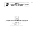
6.4 BALANCE CHART (FIG. 6-1)
1. Balance chart description
J
The varying load scales are in the upper part of the page. The separate
scales are plotted in the middle part of the page. The chart of the
centre-of-gravity position vs. sailplane weight is given in the bottom part
of the page. The region of the allowable centre of gravity range is the
slanted shape in the chart and it refers to all flight conditions.
( Cont. )
6-2
Jan 4/02
~
L 23 SUPER - BLA N IK
686 04 KUNOVICE
CZECH REPUBLIC
SAI LP LANE FLIG HT MANUA L
Do - L 23. 1014.5
2. Directions fo r the balance chart use
See FIG.6-1 on Page 6-4, Line
o.
· Make a dot on the Empty Sailplane Center of Gravity Range
corresponding with the value shown on the Balance Record on page
6 - 5.When the wing tip extensions are used, move the center of gravity
of the empty sailplane 1% MAC in aft direction. Draw a vertical down
to Line 1. The intersection of the vertical and Line 1 is Point A.
· Next, use Scale 1 at the top of the chart. Measure the distance from 0
on that scale to a number corresponding with the weight of the front
pilot + parachute + ballast seat (if used). Transfer this distance from
Point A to the left,draw a vertical, and mark the intersection with Line
2 as Point B.
· Next, use Scale 2. Measure the distance from a on that scale to a
number corresponding with the weight of the rear pilot + parachute.
Transfer this distance from Point B to the left, draw a vertical, and mark
the intersection with Line 3 as Point C .
· Next, use Scale 3 for any changes in the front instrument panel.
Measure the distance from 0 on that scale to a number corresponding
with the weight of any instrument added or removed. Transfer this
distance from Point C to the left (if an instrument is added), to the right
(if removed). Draw a vert ical , and mark the intersection with Line 4 as
Point D.
· Next, use Scale 4 for any changes in the rear instrument panel in the
same fashion as in the previous paragraph. That is how you arrive at
point E. Draw a vertical on down to the lower part of the chart.
Now, use the weight scale on the lower left part of the balance chart.
Mark the sum of all weights: Empty sailplane +front pilot + parachute
+ ballast seat + rear pilot + parachute + instrument changes +
baggage.
· Draw a horizontal line from the mark to the right. The center of gravity
position is at the intersection of this horizontal line with the vertical
from Point E.
· If this intersection is inside the slanted shape, the glider is loaded
correctly. If the intersection is outside, the glider has to be reloaded.
Note: The baggage weight is to include any battery, oxygen
bottle, water bottle etc. Items in the baggage compartment
have no influence on the centre of gravity position,but they
must be included to the sum of all the weights.
6-3
Jan 4/02
~
L 23 SUPER - BLANIK
68604 KU NOVICE
CZECH REPUBLIC
SAILP LANE FLI G HT MANUAL
300
Scale 1
Ib
Scale 2
Ib
Scale 3
Ib
Scale 4
Ib
250
200
Do - L 23. 1014.5
100
150
50
0
300
200
100
I
l
I
30
10
10
_LLI
fir
Line 0
62
EMPTY SAILPLANE CENTER OF GRAVITY RANGE
Front Pilot + parachute + seat balast
300
200
250
150
70
50
100
Line 1
Rur Pilot
.j.
300
parachute
200
100 A
Line 2
30
Fronllnstrument panel changes
10
Une3
10
Rear instrument panel changes
Line 4
D
Line 5
E
Weight Ib
Aft of r""r llot seat - no innuence
on centre of gravity position
23
40
1000r-------~~~~~~------_1
900 r----------Y~~~~~----_1
700~--------------~MM~WWWr~
23
40
FIG . 6 - 1
6-4
Jan 4/02
m
.................. "
III
::J
~
o
!,
Approved
i')
No.
Empty
weight
Ib
I
c/g
pas,
% MAC
Max, baggage (22 Ib)
No baggage (0 Ib)
Half baggage (11 Ib)
OJ
0°
I~
z
(')
Front seat
Rear seat
Front seat
Front seat
Rear seat
m
Rear seat
I Signed
Date
Max, I Min. I Max. I Min. I Max. I Min. I Max.
1.
'2;; 7-
1 I!U; ·7- I/7-C1
fL()
r
f)
C ,':2
.... Cl T
/b-/I
c::?
JJ
:o A
me
-oZ
cO
0)<
ro
om
(')
5"- '< " '~"'~"""'"
o
C 2. \,'" "~.;p
I~
.) ..(~
CI
' J" '\
• ../.r
':'J,.:;''i''
'1:[
',I '
::c
en
l>
r
r
w
m
c:
"0
l>
Z
2.
?-£ 6, L IflJ,
-
3.
1 1£87- 1-
1/33
1-- 128+1 _. If4if 1 -~ l,qttf\:;;t /--
/fb-~-
I
7-2 G; {?-
16"b~ 1
If> '~ I -
12 8 '71-
~i
"T1
i- ---i
I'lft If 1- I~£::;. 1- IfS-!J~ I .-- Ie&s ,:J-
,,'.'
S;,
'> ri"
Dt
.'
1.~2·~ ~\.~
\"~
7
(J)
"0
:::t:
-i
OJ
s:
l>
z
c:
l>
o
o
r
1. Single seat
I\.)
2. Tandem seater-max front pilot
o
3. Tandem seater-max rear pilot
(J)
0)
en
::IJ
r
I
r
r-v
C>
r
I
r-----~--J----t----+_--~----~--~--~---
~
m
Min. I Max. I Min. I Max. I Min.
/
~ Q 6/2. I(J),
0
»
r
»
Permitted crew + passenger weight (Ib) with:
OJ
N 0)
mO)
01
w
~
~
m
r
l>
-7\z
~
L 23 SUPER - BLANIK
68604 KUNOVICE
CZECH REPUBLIC
SA ILPLA N E FLIGHT MANUA L
Do - L 23. 1014.5
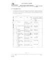
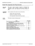
6.6 EQUIPMENT LIST
Standard (S) items must be insta lled for all operations. Optional (0) items
are available for installation. Installed items for each sailplane equipment
list will be marked w ith an "X " and included in the Empty Weight/c .g. pas
of the Balance Record.
- -
0
S
Subject
Altimeter
X
1
Type
Mass
Ib
(kg)
U15934P-3
front instr.panel
rear instr.panel
0.90
(0.41 )
Arm from the Date of
reference plane nstallation
(rib No.1) ft (mm) - 5.82 (-1774)
- 1.81 (-551)
.
X
2
Airspeed indicator LUN 1106.15-8
front instr.panel
rear instr.panel
0.88
(0.4)
- 5.83(-1777)
- 1.82(-555)
3
X Electric
LUN 1211.1
turn-and-bank/side front instr.panel
indicator
rear instr.panel
0.79
(0.36)
- 5.83(-1777)
- 1.82(-555)
4
X Vertical speed
indicator ± 1000
ft/min
or
Vertical speed
indicator ± 10
knots
LUN 1141.02
front instr.panel
rear instr.panel
1.06
(0.48)
- 5.87(-1789)
-1 .87(-570)
LUN 1141.04
front instr. panel
rear instr.panel
1.06
(0.48)
- 5.87(-1789)
- 1.87(-570)
--
-
..
X Vertical speed
indicator ± 6000
5
I
I
ft/ min
or
IVertical speed
l..
indicator + 60
knots
LUN 1147.12-8
front instr.panel
1.1
(0.5)
LUN 1147.23-8
front instr.panel
1.1
(0.5)
-
~
- 5.802(-1768)
I
- 5.802(-1768)
I
I
I
I
I
t
( Cant. )
CD Apr 9/02
6-6
~
L 23 SUPER - BLANIK
686 04 KUN OVICE
CZECH REPUBLIC
S
0
SAI LPLANE FLI GHT M ANUA L
Subject
Type
Mass
Ib
(kg)
6
X Magnetic compass LUN 1221.1-8
7
X Accelerometer
8
X Radio station
0.23
front instr.panel (0.105)
rear instr.panel
AM"10 front
instr. panel
0.55
(0.25)
Do - L 23. 1014.5
Arm from the
Date of
reference plane instalation
(rib No. 1)
ft (mm)
- 5.79(-1765)
- 1.79(-546)
- 5.51 (-1679)
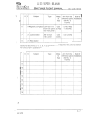
Optional (0) Items 3, 4 , 5, 6, 7 as applicable is required for pilot's station
for cloud flying operations.
S
0
Subject
Type
Mass
Ib
(kg)
Arm from the
Date of
reference plane instalation
(rib No.1)
ft (mm)
9
10
11
)
12
13 14 15 16 )
6-7
Jan 4/02
L 23 SUPER - BLANIK
~
686 04 KUNOVICE
CZECH REPUBLIC
SAILPLANE FLIGHT MANUAL
Do - L23. 1014.5
S ECTION 7
Sailplane and systems desc ription
CONTENTS
Jan 4/02
7.1
Introduction
7 .2
Saiiplane description
7.3
Front seat ballast
7.4
Front cockpit
7.5
Rear cockpit
7 _ 1
L 23 SUPER - BLANIK
~
68604 KUN OVICE
CZECH REPUBLIC
7.1
SAI LPLA N E FLIGHT MANUAL
00 - L23. 1014.5
IN TRODUCTIO N
The description and operation of the sailplane and its systems are given in the
Maintenance Manual of the L 23 SUPER - BLANIK Sailplane.
7.2 SAILPLANE DESCRIPTION
T he L 23 SUPER - BLANIK sailplane is a cantilever, high-wing , two-seat glider
of all-metal structure. The rudder, elevator and ailerons are fabric covered. In
the forward section part of the fuselage there are front and rear cockpits. Both
cockpits are covered with a two-part canopy which can be jettisoned in flight.
Both cockpits are equipped with all sailplane flight control including flight and
navigation instrument panels. The sailplane is equipped with tow hooks either
for winch or aero-tow take-off.
Wings including ailerons and air brakes,are attached to the fuselage at six
suspension points (three on each side).There is a possibilityof using the wing
tip extensions which enlarge the wing span from the 81 st series.They may be
connected to the standard wing instead of the laminated wing tips. The vertical
stabilizer is permanently fixed to the rear fuselage section. The horizontal
stabilizer is fastened by hinges on the top of the vertical stabilizer.
Elevator and aileron controls are actuated by control push rods and control
cables, the rudder control is pedal- operated also by control push rods and
control cables. Air brakes are controlled by control levers. The elevator trim
tab is controlled by the control lever.
The sailplane is equipped with the main landing gear and the tail landing
gear.The main landing gear is mechanically semi-retractable with an
oleo-pneumatic shock-absorber and a mechanical brake. The tail tanding gear
is equipped with a wheel and shock-absorber. Cockpits are ventilated by cold
air tapped from the nose part of the fuselage. The baggage compartment is
behind the rear cockpit. Both cockpits are upholstered.
7.3 FRONT SEAT BALLAST
)
A.Seat insta ll ation, Fig. 7-1
1. Disassemble and remove the seat from the front cockpit.
2. Put the seat with ballast into the free space and insert stirrups (pos.
2) in the rear part of the seat into the chamber on the rest suspender.
3. M a vet h e I eve r son the sea t sid e sup war d s (p a wi s will s h ift in the seat
. face) and fold the seat (pas. 1) to the floor.
4. Move the levers down'wards, the pawls will shift out and they must
)
Jan 4/02 shift in the hole on the floor frame (if the pawls do not shift in the
holes, move the seat to both sides to enable shifting the pawls in the
holes).
7-2
L 23 SUPER - BLANIK
~
68604 KUNOVICE
CZECH REPUBLIC
SAI LP LAN E FLIGHT MANUAL
Do - L23. 1014.5
B.Seat removal Removal is carrie d out in a reverse order to installation. 1
2
FIG. 7 - 1
)
Jan 4/02
7-3
LS
L 23 S UPER - BLA N IK
68604 KUNOVICE
CZECH REPUBLIC
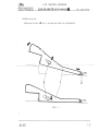
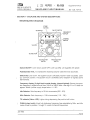
7 .4
SAI LPLANE FLIGHT MANUAL
Do - L23. 1014.5
FRO NT COCKP IT - STAN DA RD 28
12
18
11
30
9
Fig. 7-2
)
(1)Control column, (2)Rudder pedals, (3)Airbrake handle, (4)Elevator trim handle, (S)Wheel
brake handle, (6)Landing gear handle , (7)Rope release mechanism, (S)Rudder pedals
adjustment, (9)Cockpit hood opening handle, (10)Handle of canopy jettison, (11 )Air vent pull
rod with handle, (12)Turn-and-bank indicator switch, (13)Altimeter, (14)Airspeed indicator,
(1S)Turn-and-bank indicator, (16)Compass, (17) and (18)Vertical speed indicators, (19)Label
"Canopy lift off" , (20)Label "Airbrakes extended", (21)Label "Airbrakes retracted", (22)Label
"Elevator trim control", (23) Label "Wheel brake ", (24)Label "No smoking", (2S)Label "Tow
release ", (26)Label "Max. airspeeds", (27)ldentification number, (2S)Label "TURN-ANO-BANK
INDICATOR", (29) Label "Manoeuvers with wing tip extensions forbidden", (30)Label "Air vent ",
(31}Label "Landing gear extended", (32)Label "Landing gear retracted", (33)Label "Adjustment
of pedals", (34)Label "Max. pilot weight", (35)Label "Canopy jettison", (36)Label "Operating
limitations ", (37)Label "Seat position", (3S)Label "Center of gravity", (39)Radio control button,
(40)Battery for turn-and-bank indicator, (41)Microphone, (42)Deviation chart, (43)Label
"Max. alowable speed vs altitude''', (44)Positional pin of landing gear opened and locked
position (the landing gear handle must be located in front of the positional pin in flight
direction)
Jan 4/02
7-4
~
68604 KUNOVICE
CZECH REPUBLIC
L 23 SUPER - BLANIK
SA ILPLANE FLIGHT MANUAL
Do - L23. 1014.5
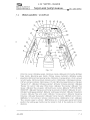
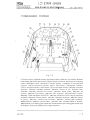
7.5 REAR COCKPIT - STANDARD Fig. 7-3
(1)Control column, (2)Rudder pedals, (3)Airbrake handle, (4)Elevator trim handle, (5)Wheel
brake handle, (6)Landing gear handle, (7)Rope release mechanism, (S)Cockpit hood opening
handle, (9)Oeviation chart, (10)Handle of canopy jettison, (11)Battery for turn-and-bank
indicator, (12)Turn-and-bank indicator switch, (13)Altimeter, (14)Airspeed indicator,
(15)T urn-and-ba nk indicator, (16) Compass, (17) Vertical speed ind icator, (1S) Label "Ai rbrakes
extended", (19)Label "Airbrakes retracted", (20)Label "Canopy lift off", (21)Label "Max.
airspeeds", (22)Label "Elevator trim control", (23)Label "Wheel brake", (24)Label "No
smoking", (25)Label "Tow release ", (26)Label "Max. airspeeds", (27)ldentification number,
(2S)Label "TURN-AND-BANK INDICATOR", (29)Label "Manoeuvers with wing tip extensions
forbidden", (30)Label "Canopy jettison", (31)Label "Operating limitations", (32)Label "Center
of gravity", · (33)Label "Landing gear extended", (34)Label "Landing gear retracted",
(35)Microphone, (36)Radio control button, (37)Label "Max. alowable speed vs altitude",
(38)Positional pin of landing gear opened and locked position (the landing gear handle must
be located in front of the positional pin in flight direction)
Jan 4/02
7-5
~
68604 KUNOVICE
CZECH REPUBLIC
L 23 SUP ER - BLANIK
SAILPLANE FLI GH T MANUAL
Do - L 23. 1014.5
SECTION 8
Sailplane handling, care and maintenance
CONTENTS
8.1
Introduction
8.2
Sailplane inspection period
)
Jan 4/02
8-1
L 23 SUPER - BLANIK
~
68604 KU NOVICE
CZECH REPU BLlC
I
8 .1
SA ILP LANE FLI GHT MANUAL
Do - L 23. 1014.5
IN TR ODUCTION
Procedures r e commended by the manufacturer for proper ground
handling, servicing and maintenance, which must be followed if the
sailplane is to retain new-plane performance and dependability,are
given in the Maintenance Manual of the L 23 SU PER - BLAN I K Sailplane.
,
8. 2
SAILPL AN E INSPECTION PERIOD
Maintenance and servicing of the sailplane are provided in the L 23
SU PER-B LAN I K sailplane Maintenance Man ual Do - L 23 1031.3 ( see
Section 5 ).
)
Jan 4/02
8-2
~
68604 KUNOVICE
CZECH REPUBLIC
L 23 SUPER - BLANIK
SA ILPLA NE FLIG HT MANUAL
Do - L 23. 1014.5
SECTION 9
Supplements
CONTENTS
9.1
Introduction
9.2
List of inserted Supplements
9.3
Supplements inserted
)
Jan 4/02
9-1
~
L 23 S UPER - BLANIK
68604 KUNOVICE
CZECH REPUBLIC
Date of
insertion Doc. No.
SAILPLANE FLIGHT MANUAL
Do - L 23.1014.5
Title of inserted supplement \'
.I
Jan 13/99
9-3
~
l23 SUPER - BlANIK
686 04 KUNOVICE
CZECH REPUBLIC
9 .1
SA ILPLANE FLIGHT MANUAL
Do - L 23.1014.5
INTRODUCTION
Section 9 of this Sailplane· Flight Manual provides supplemental
information for optional equipment which is installed on the sailplane
and additionaly it may contain the supplementary information on
sailplane operation.
The information contained in this document supplements or superseds
the basic Sailplane Flight Manual where covered in the sections
contained herein. For limitations, procedures and performance not
contained in this supplement, consult the basic Sailplane Flight Manual.
9.2·
LIST OF INSERTED SUPPLEMENTS
Date of
insertion
Title of inserted supplement
Doc. No.
1
Not used
2
Not used
3
Not used
Feb 15/02
4
ILEG SN 10 Sailplane Computer Feb 15/02
5
VHF DITTEL FSG 71 M Transceiver 6
Emergency Locator Transmitter Ameri- King AK-450 ELT Feb 15/02
7
Volkslogger VL-01 GPS Flight Data Recorder Feb 15/02
8
Front and rear cockpits
I
I
I
I
I
)
I
i
!
----+- - - - ~ "--
i
J
I
I
i
I
I
Jan 13/99
--
I
9-2
L 23 SUPER - BLANIK
686 04 KUNOVICE
CZECH REPOBLIC
SAILPLAN E FLI GHT MANUAL
Supplement No. 4
Do - l23 .1014.5
SUP PLEMENT No.4
I LEC SN 10 Sailplan e Computer
Serial Number
029005
Registration number
N410BA
This supplement must be attached to the Sailplane Flight
Manual when the ILEC SN 10 Sailplane Computer is
installed.
The information contained herein supplements or
supersedes the basic manual only in those areas listed
herein. For limitation, procedures and performance
information not contained in this supplement, consult the
basic Sailpl ane Flight Manual.
Revision No.
Description of Revision
. Revised Pages
"
,
,~,.'
.
"."
,
Date
'
"
"
Not subject to CAA approval.
)
Jan 4/02
1 of 4
L 23 SUPER - BLANIK
686 04 KUNOVIGE
CZECH REPOBLIC
!
SA I LPLANE FLIG HT MANUAL
Supplement No. 4
Do - L23 .1014.5
SECTION 1 - GENERA L - Not affected
SECTION 2 - LIMITATIONS
System function and accuracy was not judged by GAA Czech Republic.
Do not use ILEG as primary information source .
SECTION 3 - EMERGENCY PROCEDURES - Not affected
,
~.
" SECTION 4 - NORMAL PROCEDURES
I L EC S N 10 Sa i I plan e Comp u'ter
Note:
0
peratio n
Detailed description of t he operation is mentioned in the SN 10 User
Manual, Software Version 2.21, revision date 17-May-2001. Battery switch on the front instrument panel must be on before SN 10 switching on. SN 10 is switched on by turning clockwise of the Off/Vol knob. Audio . signals volume is set by means the same knob. WAR N I N G:
)
SN 10 is not a replacement for primary flight instruments and pilot's decisions. In case of incorect inputs, the SN 10 will
display incorect and possibly dangerous information. All
decisions during flight must be made by the pilot!
Suggested preflight checklist for competition mode:
(see lIec SN 10 User Manual, Appendix B)
- Verify altimeter setting in the Alt field
- Set desired finish altitude in the Fin field (field elevation plus safety
height)
- Check battery voltage in the Volts field
- Set timers if applicable (STI and RST min fie lds)
- Set the fina l gl ide Wind setting from the weather briefing
J
Set Water and Bugs (cant.) Jan 4/02
2 of 4
L 23 SUPER - BLAN IK
686 04 KUNOVI CE
CZECH REPOBLI C
SAILPLAN E FLIGHT MANUAL
Supplement No. 4
Do - L23 .1014.5
- Set t he p la n n ed T as k
- Flight recorder: Clear any prior-day flight record (Reset). Set point Cy linder size. Suggested preflight checklist f o r club mo d e:
(see Il ec SN 10 U ser Manual, Appendix B)
CAUTION: IF YOU TURN OFF THE SN 10 SOME SETTINGS WILL RESET
TO THEIR DEFAULT VALUE. DO NOT T URN OFF THE SN 10
AFTER YOU DONE YOUR CHECKLIST.
- Verify the altimeter setting in the Alt field . - Set desired arival altitude. over t he ground in the Arv field . - Set Water and Bugs (on the Clu .b Settings page) "
- Check battery voltage Volts (on the Club Settings page) Set the final glide Wind setting from the weather briefing (on the Club
Wind page)
Using the SN 10 with a Volkslogger
Description is mentioned in the SN 10 User Manual, Appendix G.
Volksloger flight data recorder is switched on automatically when SN 10
is switched on.
.
\
i
SECTION 5 - PERFORMANCE - Not affected
SECTION 6 - WEIGHTS AND BALANCE
SN 10 sailplane computer:
weight 1. 57 Ib (0.71 kg),
arm -72.05 in (-1,830 mm)
SN 10-2 repeater: weight 0 .93 Ib (0.420 kg), arm -22.44 in (-570 mm)
, Variometer RAZ : weight 0.40 ib (0.18 kg). arm -69.69 in (-1,770 mm)
J
,.'
Jan 4/02
3 of 4
L 23 SUPER - BLANIK
686 04 KU NO VICE
CZECH REPOBLIC
SAILPLANE FLIGHT MANUAL
Supplement No. 4
Do - L23 .1014.5
SECTIO N 7 - SAILPLANE AND SYSTEM DESCR IPTI ON
lIec SN 10 sailplane computer is installed in the sai l plane. Control boxes
with display are located on the front and rear instrument panel. Inputs
from temperature probe, pitot-static system and GPS unit from
Volkslogger are led into SN 10. Data are presented on the displays and
RAZ variometer which is located on the front instrument panel.
!l ec SN 10 Sailp l ane Computer controls
Off/Vol knob:
switches on SN 10 by turning clockwise and sets audio
signals volume. Repeater on the rear instrument panel has
not this knob.
Page/Help
knob/button:
selects SN 10 pages by turning , when it is held depressed
displays help text for the currently selected field. When you
release the button, the help text dissapears and the normal
screen is restored. For some fields a second page of help
is provided when you release button, press and release
button a second time to clear the second page.
Cursor/Enter
knob/button:
turning selects active field on the page,
pressing enters some data
Value knob:
turning changes the value of the currently selected field
1
J
) SECTION 8-
SAILPLANE HANDLING, CARE AND MAINTENANCE
Not affected
Jan 4/02
4 of 4
L 23 SUPER - BLANIK 686 04 KUNOV ICE
CZECH REPOB LIC
Do - L23 .1014.5
SAilPLANE FLIGHT MAN UAl
RECOMMENDED Il EC SETTING
See item 5.6 and 5.7 of the SN 10 User Manual , Software Version 2 .21,
revision date 17-May-2001.
5.6 GI id er pol ar setup
Do not use default setting for L 23 (it is not quite exact), create new
custom polars Custom 1
anp
Custom 2.
Custom 1 (without wing tip extensions) - Std. weight 530 kg
Airspeed
KIAS
kmfhour lAS
Vertical
speed
fpm
m/s
V
49
91
S
178
0.90
V
74.5
138
S
401
2.04
V
100
185.3
S
922
4.68
Custom 2 (with wing t ip extensions) - Std. weight 530 kg
Airspeed
KIAS
km/hour lAS
Vertical
speed
fpm
mJs
V
47.5
88
S
158
0.80
V
73.7
136.7
S
392
1.99
V
100
185.3
S
941
4.78
)
Insert this page behind Supplement No.4
Jan 4/02
1 of 2
L 23 SUPER - BLANIK 686 04 KUNOVICE
CZ ECH REPOB LIC
SA ILPLAN E FLI GH T MANUAL
Do - L23 .1014.5 5.7 Airspee d c alibration setup
KIAS
lAS km/hour
KCAS
32
60
36 66 43
80
45 83 54
100
55 102 65
120
65 121 76
140
76 141 86
160
87 162 97
180
98 182 108
200
109 202 121
225
123 228 135
250
137 253 CAS km/hour
)
)
Insert this page behind Supplement No.4
Jan 4/02
2 of 2 ~
L
68604 KUNOVICE
CZECH REPUBLIC
23
SUPER
BLANI K
Supp lement NO.5
SA ILPLA NE FLI G HT M A NUAL
Do - L23 .1 014 .5
)
SU PPLE ME NT N O. 5
V HF D ITTE L FSG 7 1M Transceiver
Serial Number
029005
Registration Number
N410BA
This supplements must be attached to the Sailplane Flight Manual when the VHF DITTEL FSG 71M Transceiver is installed . The informations contained herein supplements or supersedes the basic manual only in those areas listed herein . For limitations , procedures and performance information not contained in this supplement, consult the basic Sailplane Flight Manual. Revision No .
Revised Pages
Description of Revision
Date
-
)
Jan 4/02
1 of 5
~
686 04 KUNOVICE
CZECH REPUBLIC
L
23
SUPER
BLANIK
Supplement NO.5
SA I LPLANE FLIGHT MANUAL
Do - L23 .1014.5
SECTION 1 - GENERAL - Not affected
SECTION 2 - LIMITATIONS - Not affected
SECTION 3 - EMERGENCY PROCEDURES - Not affected
SECTION 4 - NORMAL PROCEDURES
Operating instructions for the VHF DITTEL FSG 71 M transceiver
Battery switch must be on before transceiver switching-on.
Turn ON the transceiver with the right toggle switch (lever up ON). Select the desired operating
frequency by rotating the increment/decrement knobs either clockwise or counterclockwise.
A clockwise rotation will increment the previous frequency while a counterclockwise rotation
will decrement the previous frequency. The larger inside knob will change the MHz-portion,
the smaller outside knob will change the kHz-portion. At one band-edge (000 or 975 kHz) the
following 25 kHz change will wrap around to the other band-edge. Transmission is switched
on by push-to-talk button on the front and rear control stick. Listening is ensured via speaker
box which is common for bath cockpits .
Frequency selection:
To select the desired operating frequency rotate the channel selector fully clockwise. To
tune the radio to a stored operating frequency rotate the channel selector switch to the
desired channel No. (1-10). The receiver is always tuned to the frequency appearing in
the display.
Set the left toggle switch to "Squelch OFFU-position (lever down) to override the automatic
squelch and rotate the uVOLuknob for desired listening level on the noise being produced
by the receiver. Set the left toggle switch to uSQu (lever up) to activate the automatic
squelch.
A warm-up period is not required. However, at temperatures of -20°C, the LC display
needs approx. 1 sec. until it is fully visible when frequency is changed .
For transmit operation select the desired freqUency, depress the push-to-talk button and
speak into the microphone. The microphone must be kept close to the lips in order to
cancel noise like from the engine etc. Enunciate clearly at a constant loudness. During
transmit operation, the yelow LED uTXu-indicator will light on the front panel, signaling that
the push-to-talk button is depressed.
During receive operation rotate the uVOLu knob for desired volume.
)
Caution:
Frequent transmitting and loud receiver volume reduce available operating time.
Jan 4/02'
2 of 5
~
686 04 KUNOVICE
CZECH REPUBLIC
L
23
SUPER
BLANIK
Supplement NO.5
SAILPLANE FLIGHT MANUAL
Do - L23 .1014.5
Programming the Channel Frequency Memory:
The FSG 71 M transceiver is equipped with 10 memory cells which are able to store one frequency each in the range from 118.000 to 136.975 MHz. The stored frequencies are non-volatile. Channel Frequency setting: -Rotate channel selector knob fully clockwise. -Select the desired frequency by rotating MHz- and kHz knobs. -Rotate channel selector knob to desired channel number (1 to 10). -Enter the frequency by depressing (approx. 1 sec.) the store button (STO) into the memory. If a frequency is already stored in that certain channel it will be overwritten. The function of the STO button is electrically delayed to reduce memory loss caused by accident touching. Recall of Stored Frequencies:
Rotate channel selector knob to desired channel number. The stored frequency will
appear on the display and the transceiver is tuned.
Caution:
If the built-in battery of the electronic memory is defective, the memory content is lost when
the unit is switched OFF. For safety reasons the memory battery should be changed every
five to six years by authorized personnel (recommended date of change see separate tag
unit).
Note:
Detailed operating instructions are mentioned in the Installation & Operation Manual Transceiver FSG 71 M (Document No. : 027.HB.OOE, Revision No.: (Reprint)1, Data/Issue: July 1998) ) SECTION 5 - PERFORMANCE - Not affected
SECTION 6 - WEIGHTS AND BALANCE
Transceiver block: \fl/eight 5.2 Ib (2 .36 kg), arm -38 in (-963 mm)
Battery F10023: Weight 7.6 Ib (3.45 kg), arm 14 .6 in (+ 370 mm)
Jan 4/02
3 of 5
~
L
68604 KUNOVICE
CZECH REPUBLIC
l
23
SUPER
BLANIK
Supplement NO.5
SAILPLANE FLIGHT MANUAL
Do - L23 .1014.5
SECTION 7 - SAIL PLA NE AND SYSTEM DESCRIPTIONS
VHF DlTTEL FSG 71 M controls
STORE
BunON
ON·OFF SWITCH
r-=~:-~::::::::--;""/-=:-1
FREQUENCY
DISPLAY
CHANNEL
SWITCH
VOLUME
TX INDICATOR
kHz SELECTOR
SWITCH
MHz SELECTOR SWITCH Switch ON/OFF: Lever down : power OFF, Lever up (ON): unit supplied with power.
Potentiometer VOL: To increase the receiving volume rotate the knob clockwise.
Switch SO: Lever down : the squelch circuit is off (basic receiver noise is audible). Lever
up: common position, the squelch circuit is activated (only reception of signals above
SQ-treshold) .
Frequency display (S-digit liquid crystal display, internal lighted): Shows the opera
tion frequency in digital form set from 118.00 to 136.97 MHz. Last digit "5" or "0" does not
appear. Blinks if power supply drops below 11 V DC.
kHz Selector: Sets frequency in 25 kHz increments (000 - 975).
MHz Selector: Sets frequency in 1 MHz increments (118. - 136.)
TX indicator(Yelow LED): Light.s during depressing the push-to-talk button.
)
CHAN (rotary knob): Knob fully clockwise: frequency free selectable by MHz- and kHz
knobs. Knob on position 1 trough 10: recall of channel frequencies.
Jan 4/02
4 of 5
~
68604 KUNOVIC E
CZECH REPUBLI C
L
23
SUPER
BLANIK
Supplement NO.5
SAILPLANE FLIGHT MANUAL
Do - L23 .1014.5
STO button: By depressing the STORE-button the displayed frequency is entered in one of
the 10 electronic memories provided that the CHAN switch is at one of the 1 trough 10
position.
SECTION 8 - SAILPLANE HANDLING, CARE AND MAINTENANCE - Not affected
)
Jan 4/02
5 of 5
~
L 23 SU PER - BLAN IK
686 04 KUNOVICE
CZECH REP OB LIC
SAI LP LA NE FLIGH T MANUAL
Supplement NO.7
Do - L23 .1014 .5
SUPPLEMENT No.7
Vol k slogger VL-01 G PS Flight Data Recorder
Serial Number
029005
Registration Number
N410BA
Th is supplement must be attached to the Sailplane Flight
Manual when the Flight Data Recorder Volkslogger
VL-01 GPS is installed .
The information contained herein supplements or
supersedes the basic manual only in those areas listed
herein . For limitation, procedures and performance
information not contained in this supplement, consult the
basic Sailplane Flight Manual.
Revision No. ,
Revised Pages
Description of Revision
Date
Not subject to CAA approval
)
Jan 4/02
1
nfl
~
L 23 SUPER - BLANIK
686 04 KUNOV ICE
CZECH REPOBLIC
SAILPLANE FLIGHT MANUAL
Supplement NO.7
Do - L23 .1014.5
SECTION 1 - GENERAL - Not affected
SECTION 2 - LIMITATIONS
System function and accuracy was not judged by CAA Czech Republic. Do not use VOLKSLOGGER as primary in f ormation source. SECTION 3 - EMERGENCY PROCEDURES - Not affected
SECTION 4 - NORMAL PROCEDURES
Vo l kslogger VL-01 GPS Flight Data Recorder operation
Note: o eta i led des c rip ti 0 n. 0 f the 0 per a t ion ism e n t ion e din the
VOLKSLOGGER User Manual, Edition 1.7.2, English 05-07-2000
for Volkslogger Firmware 3.6, Subrelease -174, Hardware 3.4.
Flight data recorder has no own power switch. It is switched on
automatically after Ilec SN 10 sailplane computer switching on because
these instruments are interconnected each other.
Data enering before flight ( for competition flights ):
(see VOLKSLOGGER User Manual item 5.6.)
It is necessary to enter desired data (pilot name, sailplane number, task
etc.) before flight into the digital flight declaration form.
)
SECTION 5 - PERFORMANCE - Not affected
SECTION 6 ~ WEIGHTS AND BALANCE
Volkslogger installation: weight 1.00 Ib (0.455 kg), arm -29.29 in (-744 mm) \
1
./
Jan 4/02
2 of 3
L 23 SUPER - BLANIK
~
68604 KUNOVI CE
CZECH REPOBLIC
SA ILPLANE FLIGHT MANUAL
Supp le m en t NO . 7
Do - L23 .1014.5
SECTION 7 - SAILPLAN E AND SYSTEM DESCR IPTIO N
V o lkslogger flight data recorder is installed in the sailplane. It is
app r oved FAI (FAI - Sporting Code, Section 3, Annex B) for competition
using. Maximum record capacity is up to 30 hours. Geographic attitude,
GPS altitude and barometric altitude are recorded.
Volkslogger contains GPS receiver with integral antenna. Volkslogger can
be used for navigation purposes and to obtain information stored in
database (25 pilot names, 25 task - each max. 10 way points and 500
waypoints - airport included).
Recorder is located on top of the rear instrument panel to ensure
receiving from GPS sate ll ites. It is controlled by three keys located on the
instrument front side next to display.
Volkslogger VL-01 GPS Flight Data Recorder controls
5
@
•
'\
@
•
•./
•
2
3
@
1 to 3 - control keys, 4 - GPS antenna, 5 - display, 6 - plug
) The keys have different functions depending on the display and the
operati ng mode of the recorder. For instance key 1 has the fu nction of an
escape key (exiting the menu level to the next higher level) . Key 2 has
the next function. You can select the displayed menu items with it. Beside
this, in modes where you can change a value, key 2 can be considered a
(-) key, as (+) key use key 3. Key 3 also has the property of an enter
key. With it you can go to the selected menu. Every key has an auto
repeat function, which means that if it is held depressed longer than
0.5 sec, it acts as if it is pressed repeatedly in rapid succession.
)
SECTION 8-
SAILPLANE HANDLING, CARE AND MAINTENANCE
Not affected
Jan 4/02
3 of 3
~
L
68604 KUNOVICE
CZECH REPUBLIC
23
SUPER
BLANIK
Supplement No.8
SAI LPLANE FLIGHT MANUAL
Do - L23 .1014.5
SUPPLEMENT NO.8
FRONT A ND REA R COCKPITS
Serial Number
029005
Registration Number
N410BA
\)
This supplement must be attached to the Sailplane Flight
Manual of the above mentioned sailplane serial number.
The informations contained herein supplements or
supersedes the basic manual only in those areas listed
herein. For limitations, procedures and performance
information not contained in this supplement, consult the
basic Sailplane Flight Manual.
Revision No.
Revised Pages
Description of Revision
Date
)
)
Jan 4/02
1 of 6
~
686 04 KUNOVICE
CZECH REPUBLIC
L
23
SUPER
BLANIK
Supplement NO.8
SAILPLANE FLIGHT MANUAL
Do - L23 .1014.5
SECTION 1 - GENERAL - Not affected SECTION 2 - LIMITATIONS - Not affected SECTION 3 - EMERGENCY PROCEDURES - Not affected SECTION 4 - NORMAL PROCEDURES - Not affected )
SECTION 5 - PERFORMANCE - Not affected
Jan 4/02
2 of 6
~
L
68604 KUNOVICE
CZECH REPUBLIC
23
SUP ER
BLANIK
Supplement NO.8
SAILPLANE FLIGHT MANUA L
Do - L23 .1014.5
SECTION 6 - WEIGHTS AND BALANCE
6.6
EQUIPMENT LIST
Standard (S) items must be installed for all operations. Optional (0) items
are available for installation. Installed items for each sailplane equipment
list will be marked with an "X" and included in the Empty Weight/c.g . pos
of the Balance Record.
S
1
2
0
Subject
Altimeter
X
Airspeed
indicator
X
Type
Mass
Ib
(kg)
Arm from the
Date of
reference plane installation
(rib No.1)
ft (mm)
U15934P-3
front instr.panel
rear instr.panel
1.75 - 5.82 (-1774)
(0.85) - 1.81 (-551 )
LUN 1106.15-8
front instr.panel
rear instr.panel
0.88 - 5.83(-1777)
(0.4) - 1.82(-555)
pJi1
t".':}5_,/
ii
~
§ .t-~
<<"Tr,
..
....
~"'--..
<
I'.
~
S-c 3.0 ~
/,"; :'"')P
;\.; ~~:>
~u
;1 f
/i
;l
" , -,.<
3
Vertical speed LUN 1141.04
X indicator
front instr. panel
rear instr.panel
± 10 knots
6~,
'3> .'& 2
(r"'.~"': '-'- ':'\.
1.06 - 5.87(-1789)
(0.48) -1.87(-570)
~ .•_
4
Magnetic
X compass
LUN 1221.1-8
front instr. panel
rear instr.panel
0.23 - 5.79(-1765)
(0.105 - 1.79(-546)
X
Accelerometer AM-10 front front
front instr. panel
rear instr. panel
0.55 -5.83(-1777)
(0.25) -1.82(-555)
. ---- -,,1; '
./
,
£}, ~~
,
'l ~
"
;;
~~~,5
' • •
5
";/1
l\_, ui~i<5\ _)
"
, l
".71'
;
~~~Pp
·r
r..: ~..
.,
,
<l :::- " '
.
,
1
)
(Cont.)
Jan 4/02
3 of 6
~
L
68604 KUNOVICE
CZECH REPUBLIC
s
6
0
23
SUPER
BLANIK
Supplement NO.8
SAILPLANE FLIGHT MANUAL
Do - L23 .1014.5
Subject
Type
Vertical speed SN 10
X indicator
front instr. panel
Mass
Ib
(kg)
Arm from the
reference plane
(rib No. 1)
ft (mm)
Date of
installation
t2
.~t.-Jl
0.73 -5.83(-1777)
(0.33)
"
j
.j' "7
.,
l~
·
(2
\f '
'\
' ."~~
/
••/
L
f
7
8
Sailplane
X computer
X
Repeater
SN 10B
front instr. panel
SN 10-2
rear instr. panel
1.54 -5.83(-1777)
(0.7)
0.92 -1.82(-555)
(0.42)
~'~»
jdI
.~'. :4,
'4
if '
-~~:~.i" /
(, J?~~'~YI~\) ! .
\"~
1'>".
9
X
Transceiver
DITTEL FSG 71M
front instr. panel
5.2 -3.16(-963)
(2.36)
'.
.' "
ci:3/~ 2
,F~'Ia
~
' ~~~~
f::~~
.
';~
~f>~ ~""".
10
X
Battery
Battery F10023
J
'- -
.../
5-" ~/t) 2
7.6
+ 1.21 (+ 370)
(3.45)
·
" J~.."\
Z?ia
, :~05/
,/
";~-,...---.;.#"':
11
)( FHltVT
!$i? of
POL '(uReTlfN ~~(5)
>.f.j.
(I, ~4)
~W
\.
...
{
. .
"
'
"'~
'',. '!;).J
. f
:
qq~ry
12
I
13
14 1
J
Jan 4/02
4 of 6
~
L
68604 KUNOVICE
CZECH REPUBLIC
23
SUP ER
BLANIK
Supplement NO.8
SA I LP LA NE FLI GHT MA N UA L
Do - L23 .1014.5
SECTION 7 - SA ILPLANE AN D SYSTEM DESCRIPTIONS
7.4
FRONT COCKPIT
14 7 15 45 46 1
12
24
48
47
)
29
9
-.....
FIG. 7-2
)
(1)Control column, (2)Rudder pedals, (3)Airbrake handle, (4)Elevator trim handle, (5)Wheel brake handle,
(6)Landing gear handle, (7)Rope release mechanism, (B) Rudder pedals adjustment, (9)Cockpit hood opening
handle, (10)Handle of canopy jettison, (11)Air vent pull rod with handle, (12)Fuses, (13)Vertical speed indicator
SN 10, (14)Airspeed indicator, (15)Accelerometer, (16)Compass, (17)Altimeter, (1 B)Vertical speed indicator,
(19)Label "Canopy lift off' , (20)Label "Airbrakes extended", (21 ) Label "Airbrakes retracted", (22)Label "Elevator
trim control", (23)Label "Wheel brake", (24)Label "Max. airspeeds", (2S)Label "Tow release", (26) Label "Max.
airspeeds", (27)ldentification number, (28)Sailplane computer SN 1DB, (29)DITIEL FSG 71 M transceiver,
(30)Label "Air vent", (31 )Label "Landing gear extended", (32)Label "Landing gearretracted", (33)Label "Ad justment
of pedals" , (34)Label "Max. pilot weight", (35) Label "Canopy jettison ', (36)Label "Operating limitations", (37)Label
"Seat position", (38)Label "Center of gravity", (39)Radio control button, (40)DATA PORT, (41)Microphone,
(42) Deviation chart , {43 ) Label "Max. alowable speed vs altitude", (44)Positional pin of landing gear opened and
locked position (the landing gear handle must be located in front of the positional pin in flight direction) ,
(45)Label"Manoeuvers with wing tip extensions forbidden", (46) Label "Max, airspeed with wing tip extensions,
(47)Battery indicator, (48)Switch Battery 1/Battery 2", (49)Battery switch ON/OFF, (50) ELT Remote unit
(optional) .
Jan 4/02
5 of 6
~
68604 KUNOVICE
CZECH REPUBLIC
7.5
L
23
SUPER
BLANIK
Supplement NO.8
SAILPLANE FLIGHT MANUAL
Do - L23 .1014.5
REAR COCKPIT )
FIG. 7-3 ) (1)Control column, (2)Rudder pedals, (3)Airbrake handle, (4)Elevator trim handle, (5)Wheel brake handle,
(6)Landing gear handle, (7)Rope release mechanism, (8)Cockpit hood opening handle, (9)Deviation chart,
(10)Handle of canopy jettison, (11)Radio control button, (12)Vertical speed indicator, (13)Repeater SN 10-2,
(14) Airspeed indicator, (15)Accelerometer, (16) Compass, (17)Altimeter, (18) Label "Airbrakes extended",
(19)Label "Airbrakes retracted", (20)Label "Canopy lift off", (21)Label "Max. airspeeds", (22)Label "Elevator trim
control", (23)Label "Wheel brake", (24)Not used, (25)Label "Tow release", (26)Label "Max. airspeeds",
(27)ldentification number, (28)Not used, (29)Not used, (30)Label "Canopy jettison", (31)Label "Operating
limitations", (32)Label "Center of gravity", (33)Label "Landing gear extended", (34)Label "Landing gear retracted",
(35)Microphone, (36)Not used, (37)Label "Max. alowable speed vs altitude", (38)Positional pin of landing gear
opened and locked position (the landing gear handle must be located in front of the positional pin in flight direction)
)
SECTION 8 - SAILPLANE HANDLING, CARE AND MAINTENANCE - Not affected
Jan 4/02
6 of 6