1
J206 PCIB40 Technical Manual
2192-09066-000-000
Introduction
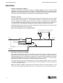
The PCIB40 is an 8-bit ISA bus add-on board providing 40 channels of digital I/O and three 16-bit
counter/timers. The digital I/O is organised into 5 groups of 8 bits. Each I/O channel may be
configured as an input or an output. The board also includes the facility to define the powerup/reset state of a group of output bits. This is extremely useful in ensuring the safe start-up of a
PC-controlled system. The 3 counter/timers are implemented using the industry-standard 8254
device. One timer can be used as a periodic interrupt generator while the other two timers can be
connected to external signals for frequency measurement and pulse generation.
The D-50 I/O connector conforms to Arcom’s standard Signal Conditioning System (SCS) and may
be used to drive a range of Signal Conditioning Boards (SCB); see Arcom’s PCbus catalogue for
more details.
Features
•
•
•
•
•
•
•
•
•
•
•
•
•
•
•
CE compliant design
40-channel digital I/O
Three 16-bit counter/timers with max count rate (input and output) 1MHz
Compact I/O addressing scheme (link selectable base address)
Link-selectable interrupt options (IRQ2,3,4,5,7)
Each channel has a current sink capability of 24mA @ 0.45V
and source current of 500µA @ 2.7V
Bit programmable for input or output
Group selection of powerup/reset state.
Board access LED (for all decoded addresses)
User controlled LED
8-bit bus interface
I/O connector conforms to Arcom Signal Conditioning System (SCS)
Operating temperature range, +5°C to +55°C
Power consumption from the host, max 300mA @ +5V
MTBF: 477,000 hours (using generic figures from MIL-HDBK-217F at ground benign)
Getting Started
•
•
•
•
•
Switch off PC
Install Board in supplied configuration
Switch on PC
Run TEST.EXE (supplied on utility disk)
An access/user LED should flash. If not check default link configuration. (Page 7)
3