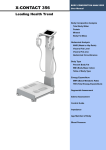
1
INSTRUCTION MANUAL
USE AND MAINTENANCE FOR
ELEVATING WORK PLATFORMS
EWP
KB 23-13 series
2013
KB-series
leadinginnovation
INDEX
0.
INTRODUCTION
1.
GENERAL INFORMATION
2.
SAFETY
3.
INSTALLATION
4.
DESCRIPTION OF THE MACHINE
5.
USE OF THE MACHINE
6.
MAINTENANCE
7.
SPARE PARTS AND ACCESSORIES
8.
ADDITIONAL INSTRUCTIONS
9.
ATTACHMENTS
User’s manual KB-series
i
leadinginnovation
INDEX
0. Introduction ....................................................................................................................................... 1
0.1. Applied Standards and Laws .................................................................................................... 1
0.2. Use of the manual ..................................................................................................................... 1
0.3. Storing the manual .................................................................................................................... 2
0.4. Disclosure limitations of the manual ......................................................................................... 2
0.5. Symbols used in this manual .................................................................................................... 2
0.6. Ways of reading and consulting the manual ............................................................................. 2
0.7. Update of the instruction manual .............................................................................................. 3
0.8. Glossary and pictograms .......................................................................................................... 3
1. General information.......................................................................................................................... 7
1.1. Identification data of the manufacturer ..................................................................................... 7
1.2. Warranty.................................................................................................................................... 7
1.3. Disclaimer ................................................................................................................................. 8
1.4. Definitions ................................................................................................................................. 8
1.5. Personnel in charge .................................................................................................................. 8
1.6. Attached manuals ..................................................................................................................... 8
1.7. General safety warnings ........................................................................................................... 9
2. Safety ............................................................................................................................................... 10
2.1. Intended use ........................................................................................................................... 10
2.2. Unauthorized uses .................................................................................................................. 12
2.2.1. Safe distance from slopes and ditches ............................................................................. 14
2.2.2. Warnings for operations carried out close to electric lines ................................................ 15
2.3. Operating environmental limits ............................................................................................... 16
2.3.1. Illumination ........................................................................................................................ 17
2.3.2. Beaufort Scale ................................................................................................................... 17
2.4. Operator's workstation ............................................................................................................ 18
2.5. Dangerous zone ...................................................................................................................... 18
2.6. Residual risks .......................................................................................................................... 18
2.7. Use of personal protective equipment .................................................................................... 19
2.8. Safety devices ......................................................................................................................... 19
2.8.1. Safety devices ................................................................................................................... 19
2.9. Warnings, prohibition and danger ........................................................................................... 20
2.9.1. Plates indicating warning, prohibition and danger in the cage .......................................... 22
2.9.2. Acoustic signals ................................................................................................................. 22
3. Installation ....................................................................................................................................... 23
3.1. Storage.................................................................................................................................... 23
3.2. Handling the machine ............................................................................................................. 23
3.2.1. Lifting the machine ............................................................................................................ 23
3.2.2. Load and unload the machine on and from the transport mean ....................................... 24
3.2.3. Transporting the machine .................................................................................................. 24
3.3. Cleaning the machine ............................................................................................................. 24
4. Description of the machine ........................................................................................................... 25
4.1. Main components .................................................................................................................... 25
4.1.1. Material supplied with the machine ................................................................................... 26
4.2. Main parts ............................................................................................................................... 26
4.2.1. Main parts of Undercarriage .............................................................................................. 26
4.2.2. Main components of the aerial part ................................................................................... 27
4.3. Overall dimensions ................................................................................................................. 28
4.4. Environmental conditions ........................................................................................................ 28
4.5. Illumination .............................................................................................................................. 28
4.6. Vibrations ................................................................................................................................ 28
4.7. Sound emissions ..................................................................................................................... 28
ii
User’s manual KB-series
leadinginnovation
4.8. Gas emission .......................................................................................................................... 29
4.9. Specifications .......................................................................................................................... 29
4.9.1. Diagram Working Area ...................................................................................................... 30
4.10. Tools ....................................................................................................................................... 30
4.11. Panels and management unit ................................................................................................. 32
4.12. Standard supply ...................................................................................................................... 33
4.13. Electromagnetic environment ................................................................................................. 33
5. Use of the machine .........................................................................................................................34
5.1. Control devices and management unit ................................................................................... 34
5.2. Emergency lowering control operation ................................................................................... 40
5.2.1. Starting the auxiliary battery.............................................................................................. 43
5.3. Inspections to carry out before using the machine ................................................................. 44
5.4. Use modes .............................................................................................................................. 44
5.4.1. Use of the platform with power supply .............................................................................. 44
5.4.2. Use of the platform (EWP) with combustion motor. .......................................................... 45
5.5. Start-up ................................................................................................................................... 46
5.5.1. Starting the combustion motor .......................................................................................... 46
5.5.2. Starting the electro-pump motor ....................................................................................... 46
5.6. Translation of the platform (EWP) .......................................................................................... 47
5.7. Stabilizing the platform (EWP)................................................................................................ 47
5.8. Opening the work platform...................................................................................................... 48
5.8.1. Manual Opening of the Platform: ...................................................................................... 48
5.8.2. Automatic Opening of the Platform ................................................................................... 49
5.9. Ascending with the work platform ........................................................................................... 49
5.10. Closing and stopping the EWP ............................................................................................... 50
5.11. Emergency Stop ..................................................................................................................... 51
5.11.1. Stop caused by the load limiter .................................................................................... 51
5.12. Removing the work platform ................................................................................................... 51
5.13. Under bridge configuration – Cage rotation............................................................................ 52
5.14. Removal Platform Arm............................................................................................................ 52
5.15. Crane Version (optional) ........................................................................................................ 53
5.15.1. Diagram Working Area (crane) ..................................................................................... 53
5.15.2. Mount Crane ................................................................................................................. 54
5.15.3. Precautions for for using the crane............................................................................... 54
5.16. Winch Stand (optional) .......................................................................................................... 55
5.16.1. Diagram Working Area (winch).................................................................................... 55
5.16.2. Main Parts of Winch ..................................................................................................... 55
5.16.3. Mount Winch ................................................................................................................. 56
5.16.4. Precautions for Using the Winch .................................................................................. 56
5.16.5. Using the Winch............................................................................................................ 56
5.16.6. Maintenance of Winch .................................................................................................. 56
5.17. Downtime ................................................................................................................................ 56
6. Responsibilities of Owners ............................................................................................................57
6.1. Basic Principles ...................................................................................................................... 57
6.2. Responsibilities Upon Purchase. ............................................................................................ 57
6.3. Manuals .................................................................................................................................. 57
6.3.1. Machine Manual(s). ........................................................................................................... 57
6.3.2. Manual of Responsibilities. ............................................................................................... 57
6.4. Maintenance, Inspection and Repair. ..................................................................................... 57
6.4.1. Maintenance. ..................................................................................................................... 57
6.4.2. Inspection. ......................................................................................................................... 57
6.4.3. Repairs. ............................................................................................................................. 58
6.5. Pre-delivery Preparation. ........................................................................................................ 58
6.6. Frequent Inspection. ............................................................................................................... 58
6.7. Annual Inspection. .................................................................................................................. 58
6.8. Maintenance safety precautions. ............................................................................................ 58
6.9. Replacement parts.................................................................................................................. 58
User’s manual KB-series
iii
leadinginnovation
6.10. Maintenance training. .............................................................................................................. 59
6.11. Training. .................................................................................................................................. 59
6.11.1. Operator training. .......................................................................................................... 59
6.11.2. Assistance to user......................................................................................................... 59
6.12. Familiarization upon delivery. ................................................................................................. 59
6.13. Operation. ............................................................................................................................... 59
6.14. Assistance to users and operators. ........................................................................................ 59
6.15. Record Retention and Dissemination. .................................................................................... 59
6.15.1. Record Retention. ......................................................................................................... 59
6.15.2. Proof of Training. .......................................................................................................... 60
6.15.3. Record dissemination. .................................................................................................. 60
6.16. Modifications. .......................................................................................................................... 60
6.17. Manufacturer’s Safety Bulletins. ............................................................................................. 60
6.18. Responsibilities upon Sale. ..................................................................................................... 60
7. Responsibilities of Users ............................................................................................................... 61
7.1. Basic principles. ...................................................................................................................... 61
7.2. Manuals ................................................................................................................................... 61
7.2.1. Machine manuals. ............................................................................................................. 61
7.2.2. Manual of Responsibilities................................................................................................. 61
7.3. Inspection and Maintenance. .................................................................................................. 61
7.3.1. Frequent Inspection. .......................................................................................................... 61
7.3.2. Annual Inspection. ............................................................................................................. 61
7.3.3. Pre-start inspection. .......................................................................................................... 61
7.3.4. Maintenance Safety Precautions....................................................................................... 62
7.4. Replacement Parts. ................................................................................................................ 62
7.5. Maintenance Training. ............................................................................................................ 62
7.6. Operator Training and Retraining. .......................................................................................... 62
7.6.1. Trainee Records. ............................................................................................................... 62
7.7. Familiarization Before Use. ..................................................................................................... 62
7.8. Work Place Inspection. ........................................................................................................... 63
7.9. Determination of Hazardous Locations. .................................................................................. 63
7.10. Operator Warnings and Instructions. ...................................................................................... 63
7.11. User as Operator. ................................................................................................................... 65
7.12. Shutdown of Aerial Platform. .................................................................................................. 65
7.13. Record Retention and Dissemination. .................................................................................... 66
7.13.1. Record Retention. ......................................................................................................... 66
7.13.2. Record Dissemination ................................................................................................... 66
7.13.3. Proof of Training. .......................................................................................................... 66
7.14. Modifications. .......................................................................................................................... 66
7.15. Manufacturer’s Safety Bulletins. ............................................................................................. 66
8. Responsibilities of operators ........................................................................................................ 67
8.1. Basic Principles. ...................................................................................................................... 67
8.2. Manuals ................................................................................................................................... 67
8.2.1. Machine Manuals. ............................................................................................................. 67
8.2.2. Manual of Responsibilities................................................................................................. 67
8.3. Prestart Inspection. ................................................................................................................. 67
8.4. Problems or malfunctions. ...................................................................................................... 67
8.5. Training, Retraining, and Familiarization ................................................................................ 68
8.5.1. General Training. ............................................................................................................... 68
8.5.2. Retraining. ......................................................................................................................... 68
8.5.3. Familiarization. .................................................................................................................. 68
8.6. Before Operation. .................................................................................................................... 68
8.7. Workplace Inspection. ............................................................................................................. 68
8.8. Prior to each operation. ........................................................................................................... 69
8.9. Understanding of Hazardous Locations. ................................................................................. 69
8.10. Operator warnings and instructions. ....................................................................................... 69
8.11. Record of training. ................................................................................................................... 71
iv
User’s manual KB-series
leadinginnovation
9. Responsibilities of Lessors............................................................................................................72
9.1. Basic principles. ...................................................................................................................... 72
9.2. Lessor as a Dealer.................................................................................................................. 72
9.3. Lessor as an Owner................................................................................................................ 72
9.4. Lessor as a User. .................................................................................................................... 72
9.5. Lessor as an Operator. ........................................................................................................... 72
10. Responsibilities of Lessees ...........................................................................................................73
10.1. Basic Principles. ..................................................................................................................... 73
10.2. Lessee as a Dealer. ................................................................................................................ 73
10.3. Lessee as an Owner. .............................................................................................................. 73
10.4. Lessee as a User. ................................................................................................................... 73
10.5. Lessee as an Operator. .......................................................................................................... 73
11. Responsibilities of Broker ..............................................................................................................74
11.1. Responsibilities upon sale. ..................................................................................................... 74
12. Maintenance .....................................................................................................................................75
12.1. Requirements ......................................................................................................................... 75
12.2. Introduction ............................................................................................................................. 75
12.3. Inspections carried out by the Manufacture............................................................................ 75
12.4. Hydraulic oil indicator.............................................................................................................. 76
12.5. Verification of the hydraulic oil level ....................................................................................... 76
12.6. Replacing the hydraulic oil ...................................................................................................... 76
12.7. Replacing the filtering cartridge of the hydraulic oil ................................................................ 77
12.8. Verification of leaks inside the hydraulic system .................................................................... 77
12.9. Verification of the proper operation of the controls. ................................................................ 77
12.10. Verification of the load limiter operation ............................................................................... 77
12.11. Verification of the oil inside the track reducers .................................................................... 78
12.12. Verification of the track tension ............................................................................................ 78
12.13. Replacing the track .............................................................................................................. 78
12.14. Greasing ............................................................................................................................... 79
12.15. Greasing the telescopic retracting arms .............................................................................. 79
12.16. Verification of the wear of the telescopic arm runners ......................................................... 79
12.17. Verification of the presence and integrity of the plates on the machine .............................. 80
12.18. Verification of the fastening screw tightening the rotating turret .......................................... 80
12.19. Verification of the hydraulic system operating pressure ...................................................... 80
12.20. Battery: inspections and maintenance ................................................................................. 80
12.20.1. Verification of the electrolyte ........................................................................................ 81
12.20.2. Replacing the battery .................................................................................................... 81
12.21. Periodical inspections and maintenance.............................................................................. 81
12.22. Lubrication general diagram ................................................................................................ 83
12.23. Lubricant tables .................................................................................................................... 83
12.24. Tightening torque table ........................................................................................................ 84
12.25. Periodical maintenance schedule ........................................................................................ 84
12.26. Troubleshooting ................................................................................................................... 85
13. Spare parts and acessories............................................................................................................86
13.1. Assistance .............................................................................................................................. 86
13.2. Spare parts ............................................................................................................................. 86
13.3. Accessories ............................................................................................................................ 86
14. Additional instructions ...................................................................................................................87
14.1. Waste disposal ....................................................................................................................... 87
14.2. Decommissioning and dismantling ......................................................................................... 87
14.3. Safe work procedures ............................................................................................................. 87
15. Attachments .....................................................................................................................................88
15.1. Machine drawers .................................................................................................................... 88
15.2. Electrical diagrams ................................................................................................................. 88
15.3. Hydraulic diagrams ................................................................................................................. 88
User’s manual KB-series
v
leadinginnovation
vi
User’s manual KB-series
leadinginnovation
0. INTRODUCTION
0.1.
APPLIED STANDARDS AND LAWS
This manual has been issued by the Manufacturer and is an integral part of the machine: it has been
issued in Italian, original language of the manufacturer, in compliance with point 1.7.4 of directive
2006/42/CE.
The platform (EWP) is conforming with the law provisions related to Directives 2004/108 EC and 2006/95
EC
In the applicable points, it is conforming to the harmonized standard UNI EN 280.
SAFETY STANDARDS
The device has been manufactured in compliance with the
Harmonized Technical Standards listed below:
0.2.
UNI EN ISO 12100-1
Safety of machinery - Basic concepts general principles for design – (Part 1:
Basic terminology methodology).
UNI EN ISO 12100-2
Safety of machinery - Basic concepts general principles for design – (Part 2:
Technical principles).
UNI EN ISO 13857
Safety of machinery - Safety distances to prevent hazard zones being reached
by upper and lower limbs.
UNI EN ISO 13850
Safety of machinery - Emergency stop - Principles for design.
CEI EN 60204-1
Safety of machinery - Electrical equipment of machines - Part 1: General
requirements.
UNI EN ISO 14121-1
Safety of machinery - Risk assessment - Part 1: Principles.
UNI EN 982
Safety of machinery. Safety requirements for systems and components for oil
hydraulic and pneumatic transmissions. Hydraulic fluid power.
UNI EN 983
Safety of machinery. Safety requirements for systems and components for oil
hydraulic and pneumatic transmissions. Pneumatics.
UNI EN 953
Safety Of Machinery - Guards - General requirements for the design and
construction of fixed and movable guards.
UNI EN 349
Safety of machinery - Minimum gaps to avoid crushing parts of the body.
UNI EN 280
Aerial platforms
ANSI/SIA A92.5:2006 &
CSA 354.1:2004 &
ANSI B30.5:2011
American National Standard Boom-Supported Elevating Work Platforms
USE OF THE MANUAL
This instruction manual provides information on transport, use and maintenance of the platform (EWP),
which is also referred to as machine.
Before starting the machine, the operator must have read and understood the instructions provided,
especially those regarding safety.
If doubts arise on the correct interpretation of the instructions, contact the Manufacturer or the authorized
Assistance Centers for any clarifications.
User’s manual KB-series
1
leadinginnovation
0.3.
STORING THE MANUAL
This manual is an integral part of the platform (EWP) and it must:
- be stored in a place easy to access, dry and repaired from sunlight;
- be attached to the machine in the event of transfer of property and it must be stored intact for the entire life
of the platform (EWP), until its demolition.
In the event it is lost or worn, a new copy must be requested to the Manufacturer.
0.4.
DISCLOSURE LIMITATIONS OF THE MANUAL
Technical information contained in this instruction manual are property of Cormidi Srl and must be
considered confidential. Therefore, its reproduction, even partial, without written authorization of the
Manufacturer is prohibited.
Moreover, using this manual for purposes different from that indicated is prohibited.
Any violations will be prosecuted to the full extent of the law.
0.5.
SYMBOLS USED IN THIS MANUAL
The symbols are used to highlight the operations involving risks, for safety purposes.
In order to operate safely, the highlighted instructions indicating useful information and important
procedures must be complied with.
DANGER:
indicates an imminent hazardous situation that may cause injuries or death for non-compliance
with the instructions.
ATTENTION:
indicates an potential hazardous situation that may cause serious injuries or death for noncompliance with the instructions.
CAUTION:
indicates a potential hazardous situation that may cause injuries to the operator or damage
the machine for non-compliance with the instructions.
0.6.
WAYS OF READING AND CONSULTING THE MANUAL
The manual is divided into chapters, according to an order of presentation of the information.
The index facilitates displaying information and allows identifying it quickly.
The instruction manual consists in a cover, index and a series of chapters (sections).
Every figure is combined with a progressive number for each chapter.
Abbreviations:
Sec.
= section
Chap. = chapter
Para = paragraph
Pg
= page
Fig.
= figure
Tab.
= table
Unit of measure.
The units of measure are those indicated in the international system (IS).
ATTENTION:
- This instruction manual provides some illustrations of the platform (EWP) with removed
guards or panels.
- Never use the machine without the guards and protection devices.
2
User’s manual KB-series
leadinginnovation
0.7.
UPDATE OF THE INSTRUCTION MANUAL
The Manufacturer reserves the right to modify the project and implement the machine without informing
the Customers or updating the Manual already delivered to the user.
Furthermore, in the event modifications have been applied to the machine at the Customer's premises,
which have been agreed with the Manufacturer and involve the modification of the Instruction Manual, the
manufacturer will send to the holders the chapters involved with its new global revision model.
According to the indications of the updated documentation, the user is responsible for replacing the old
chapters of the all the copies held with the new ones, as well as the initial page and index of the new revision
level.
The manufacture is responsible for the descriptions indicated in Italian; any translation cannot be fully
verified, therefore, if an incongruence is detected, refer to the Italian version and contact our Sales Office,
who will carry out the due modifications.
0.8.
GLOSSARY AND PICTOGRAMS
This paragraph indicates uncommon terms or terms with meaning different from the common one.
The abbreviations used are described below as well as the meaning of the pictograms to indicate the
qualification of the operator and status of the machine; their use allows providing information on the proper
and safe use of the machine quickly and univocally.
Dangerous zone: Zone inside and/or close to the machine, where the presence of a exposed person is a
risk for his/her safety and health.
Exposed person: Any person who is found, entirely or in part, in the dangerous zone
Operator: A person in charge to install, run, adjust, carry out maintenance, clean, repair and transport the
machine
Man-machine interaction: Any operation where the operator must interact with the machine during any
phase of the operation;
Qualification of the operator: Minimum level of skills the operator must have to carry out the operations
described above;
Number of operators: The number of operators, assessed by the manufacturer, must be suitable for
carrying out the described operation; therefore, a different number of operators can compromise the
expected result or endanger the safety of the involved personnel.
Status of the machine: the status of the machine includes the operation mode, e.g. the drive, stop, etc,
safety conditions on the machine, such as protection devices (include and excluded), emergency button
pressed, insulation type of energy sources, etc.
Residual danger: A danger that has not been possible to remove or reduce during the designing phase,
against which the protection devices are not (totally) effective; the manual provides information about it
and instructions and warnings to allow solving it (see 5.4 and 6.5.1 of European standards EN 12100-1
and EN 121000-2);
Safety component: Component used to ensure safety, whose failure or malfunction affects safety and/or
health of the exposed persons (e.g. lifting equipment, fixed, mobile or adjustable guard, electric,
electronic, optical, pneumatic or hydraulic device that interlocks a guard, etc).
Elevating mobile work platform (EWP): machine that allows one or more persons to reach high positioned
workstations being inside a work platform.
Work platform: Closed platform (cage) or cabin that can be moved under load in the required work position
and from which operations, such as repairs, inspections or similar, can be carried out.
Extendable structure: structure connected to the base frame and work platform. Consisting in pantograph
telescopic or articulated arms that allow handling the work platform.
Frame: Base of the EWP.
Outriggers: mechanisms used to stabilize the EWP, made with extendable arms and hydraulic jacks.
P&T: arm lifting and lowering movement arm around a fulcrum.
Jib: extendable articulated arm that connects the work platform (cage) with the telescopic arm.
Crane: fixed arm with a hook for the use of the machine as a crane.
Winch: fixed structure equipped with hydraulic winch for the use of the machine in the configuration winch.
Pictograms provide very important information/provisions, especially concerning safety. Failure to comply
with them can involve:
- danger for the safety of the operators;
- loss of the warranty;
- declination of the responsibility of the manufacturer
User’s manual KB-series
3
leadinginnovation
•
•
•
SAFETY PICTOGRAMS
Pictograms inside a triangle indicate DANGER.
Pictograms inside a circle impose OBLIGATION/PROHIBITION.
Pictograms inside a rectangular indicate a provision that if not carried out can involve serious danger.
Dangerous electric voltage
Prohibition to use any object to reach
heights exceeding that indicated in the
work area diagram.
Generic danger.
Prohibition to loads
platform.
Danger of crushing lower limbs.
Prohibition
to carry out
welding,
perforation, grinding or any other operation
that can weaken the structure without
authorization of the manufacturer.
Danger - Always stabilize on a solid and
consistent ground.
Danger, do not use with wind, which
intensity exceeds that indicated.
No access for unauthorized persons.
Wearing protective gloves must be worn.
Safety harness must be worn.
Foot protection must be worn.
Prohibition to pass through the limit
allowed of the live electric lines.
Head protection is mandatory.
using the
work
The label on the side indicates you must read and understand operator’s manual and all other
safety instructions before using this equipment (cod. C0900.07.82).
The label on the side indicates to read the technical documentation before carrying out any operation
(e.g. manual attached to the Motor) (cod. C0900.16.59).
The label on the side indicates to read the use and maintenance manual before using the devices
close to the plate, to avoid inconveniences (cod. C0900.07.90).
The label on the side indicates that the battery can be disconnected from the machine electric
circuit, by using the battery cut-off switch, linear the plate (cod. C0900.20.63).
SAFETY DISTANCE
Label that indicates serious danger to approach and stop in the machine range of
action, as there is an imminent risk of hazard (cod. C1094.02.02).
OPENING AND CLOSURE
Label that indicates the sequence of the actions required to open and/or to close
manually the arm of the platform (cod. C1094.03.62).
4
User’s manual KB-series
leadinginnovation
MAXIMUM SLOPES
Label that indicates the slopes that can be faced in safe conditions with the platform in the
transport configuration. Avoid surfaces with transversal slopes exceeding 4° and
longitudinal slopes exceeding 10°, to prevent the risk of tilting with possible serious
consequences for the operator's safety. Anyway, the ground must be solid and stable (cod.
C1094.01.62).
CRUSHING
Label that indicates a potential risk of crushing, which can cause serious injuries or death (cod.
C1094.09.02).
SHEARING
Label that indicates a potential risk of shearing, which can cause serious injuries or death (code
C1094.03.02).
HOT SURFACES
Invites to caution, as there is risk of burning due to the possibility to contact hot surfaces (code
C1094.07.02).
CAUTIOUS PROCEDURES
This label states to be cautious, remembers to take all the accident prevention
measures, regarding the use of personal protective equipment (cod. C1094.04.02).
The meaning of the pictograms is the following:
• Read the manual before starting the machine the first time, every time the operator
changes and every time a doubt on its operation arises;
• Wear hearing protection or other suitable devices;
• Wear suitable protective gloves;
• Wear suitable accident-prevention shoes.
Requirement label
Indicates the point where the operator safety belt MUST be secured, before ascending.
Warning label
indicates the operator the maximum workspace that the
platform (EWP) can reach.
Danger label
Indicates the presence (inside the panels) of current with 110 Volts voltage (or 220
Volts, depends on the configuration).
User’s manual KB-series
5
leadinginnovation
Information label
Information label which states operational procedures and restrictions.
Warning label
Indicates the maximum acoustic pressure value emitted by the machine.
Warning label
Indicates the point where the ground plate to the machine.
Warning label
Indicates the operator the maximum capacity depending on the version:
1) the maximum load that can be lifted;
2) the maximum number of operators inside the work platform.
Warning label
Indicates the maximum value of pressure under each stabilizers. Ground / floor
should be capable of sustain the maximum pressure from each of the four
stabilizers.
WARNING: Use always the platform with the factory plates under the stabilizers.
Warning label
The first indicates the lifting or fixing points, where the machine can be secured for
transport (cod. C0900.13.68). The second indicates the points for the fixing only by expressly
prohibiting the lifting (code C0900.13.71).
Label that indicates that the product meets the EU safety, health and environmental protection
requisites.
6
User’s manual KB-series
leadinginnovation
1. GENERAL INFORMATION
Identification plate
A
B
C
D
E
F
G
H
I
L
M
N
-
Model of the platform (EWP);
Serial number;
Year of manufacture;
Mass of the platform;
Maximum outreach extension of the platform is safe conditions;
Maximum dimensions on the ground with lowered outriggers;
Maximum pressure of the hydraulic system;
Electric system voltage of the platform;
Maximum weight in the work platform with two operators on board;
Maximum manual force carried out by the operator outwards the work platform;
Maximum wind speed allowed for working with the platform;
Maximum inclination of the machine frame allowed for working on the platform in safe conditions.
Note
Altering the data on the identification plate is strictly prohibited.
1.1.
IDENTIFICATION DATA OF THE MANUFACTURER
CORMIDI srl
Via Fonte, 342 - 84069 ROCCADASPIDE (SA)
tel. +39 0828-943688 - fax +39 0828-943963
e-mail: [email protected]
The machine has been manufactured in compliance with the European, US and Canada
Standards in force at the time it has been launched on the market.
1.2.
WARRANTY
Unless otherwise agreed, the warranty:
1) has a duration of 12 months from the date of delivery to the Customer;
2) entirely covers replacements or repairs of all the components of the platform (EWP) presenting defects in
the materials or processing;
3) The Cormidi Srl workshops are the only enabled to carry out operations under warranty;
4) replacements or repairs will be carried out as soon as possible at Cormidi Srl Authorized Workshops in
relation to the requirements of the Manufacturer and its personnel; any delay in applying the warranty
does not entitle the purchaser to claim damages or extend the warranty period.
5) This warranty does not cover:
a) electric components (lams, fuses, solenoids, etc.)
b) parts subject to normal wear (slides, gaskets, oil filters, etc.)
User’s manual KB-series
7
leadinginnovation
c) any other component not manufactured by Cormidi Srl (for which the relative warranty will be provided
by the original supplier).
6) The warranty becomes null and void in the following cases:
a) tampering with or modification of the platform (EWP) and its components;
b) alteration of pressures and/or removal of the seals of the hydraulic system valves;
c) improper use of the platform (EWP);
d) use of oils and filters different from those recommended by Cormidi Srl;
e) use of non-original spare parts or non-specific for the model;
f) operations carried out by workshops not authorized by Cormidi Srl;
g) use of non-suitable propulsion components (such as internal combustion engines) and with
characteristics different from those indicated by Cormidi Srl;
h) assembly of devices, accessories and equipment not approved by Cormidi Srl.
7) Cormidi Srl reserves the right to apply any modification deemed necessary to improve its products without
obligation to apply those modifications on recently manufactured platforms (EWP), which have been
delivered or that are in the process of being delivered or have been ordered.
8) For none of the above-mentioned clauses, the purchaser can claim direct or indirect damage, extension of
the warranty, termination of the contract or delay payments.
1.3.
DISCLAIMER
The manufacturer is not liable for:
- improper use of the platform;
- unauthorized modifications or interventions on the platform;
- failure to comply with traffic rules and standards regarding transport of the machine from one worksite to
another;
- failure to comply with the instructions, totally or partially;
- poor maintenance;
- use of non-original spare parts or non-specific for the model;
- event due to environmental disaster or socio-political events.
1.4.
DEFINITIONS
Dangerous zone:
any zone, inside and/or close to the machine, where a person is exposed to the risk of injuries or harmful for
health.
Exposed person:
any person who is found, entirely or in part, in the dangerous zone.
1.5.
PERSONNEL IN CHARGE
Operator:
the person or persons in charge of running the platform (EWP).
User:
the person, body or company that has purchased or rented the
machine for proper use.
Specialized personnel:
individuals who have achieved a specific study and thus are able to recognize the dangers arising from the
use of the machine and may be able to avoid them.
Authorized persons:
qualified personnel enabled by the user to carry out specific operations.
1.6.
ATTACHED MANUALS
For the proper use of the platform (EWP) refer to:
- use and maintenance manuals of the platform;
- instruction manual of the combustion motor.
8
User’s manual KB-series
leadinginnovation
1.7.
GENERAL SAFETY WARNINGS
Behaviors to be taken when using the platform (EWP) for yours and others safety.
- Do not allow unauthorized personnel to use the machine.
- Stabilize the platform on a steady ground, with limited inclinations and away from ditch edges,
excavations and manholes, etc. The ground must always be in the condition to react to the
maximum stress indicated on the outriggers plates.
- Start the machine only if the work zone is clear from operators and any obstacle that can detect
moving parts.
- The operator on the work platform must wear the protective helmet, the provided clothes and safety
belt, which must be secured to the work platform.
- Do not protrude from the work platform: keep the work position, resting the feet on the pavement.
- The provided helmet and clothes must be worn also by the operator at the base of the platform.
- Do not climb on the work platform when is already developed or get down of it if it has not reached
the rest position.
- All the operations required to reach the operation point must be carried out by the operator inside
the work platform.
- The operation from the ground is allowed only in emergency conditions.
- Activate the levers gradually and gently to avoid rough movements.
- Pay the utmost attention during the drive near docks, slopes or slippery surfaces.
- Operations carried out near electric lines of low voltage zones require the utmost attention and
caution to avoid accidental contacts with the platform (EWP) arms and lines; anyway, comply with
the relative standards in force.
- When operating near electric lines, the operator must request the manager or supervisor special
instructions and specific indications on how to carry out the work; these instructions will be
studied complying with the relative standards in force and must be strictly followed.
- Park the machine on a solid and flat ground, which must also be sufficiently
large to allow inspections.
If this condition cannot be implemented, and therefore the machine is
parked in an authorized slope, align it according to the direction of the
slope, never transversally, and apply safety wedges under the tracks.
- Stop the motor; if possible, remove the keys and immediately disconnect
the main electric switch at the bottom left, behind the track (Battery cut-off
switch, see fig. on the side).
User’s manual KB-series
9
leadinginnovation
2. SAFETY
2.1.
INTENDED USE
Before starting the Machine, read and follow the instructions contained in this Manual.
The machine can run indoors or outdoors, but always without rain, snow or strong wind (see technical
data).
The platform (EWP) can be used for high operations in the following sectors:
- construction (wall sandblasting, maintenance and coverings, structural reliefs and restorations);
- agricultural (plant pruning);
- industrial (electric line maintenance without current).
Any use different from that stated, not included or that can be supposed in this manual is considered
improper and, therefore, not allowed.
The manufacturer has made every effort in designing this machine, making it as much as possible safe.
The machine is also equipped with all the protection and safety devices, as well as all the required
information for a safe and proper use.
For this purpose, the following information has been added:
- Minimum qualification required for the operator;
- Number of operators required;
- Status of the machine;
- Residual risks;
- Required or recommended personal protective equipment;
- Prevention of human errors;
- Prohibitions/obligations on misconduct that can be reasonably
predicted.
The user can integrate the information provided by the manufacturer with additional work instructions on
the specific use, which, obviously, must not contradict that indicated in this Manual, in order to contribute to a
safe use of the machine.
IMPORTANT: The manufacturer is not liable for damage that the machine causes to persons, animals
or in the following cases:
- use of the machine by not suitably trained personnel;
- improper use of the machine;
- electric, hydraulic or pneumatic supply defects;
- improper installation;
- poor maintenance;
- unauthorized modifications or interventions;
- use of non-original spare parts or non-specific for the model;
- failure to comply with the instructions, totally or partially;
- failure to comply with specific national standards;
- disasters and exceptional events.
General requirements
•
•
•
•
•
•
•
•
•
10
Mobile elements must always be used according to that indicated by the manufacturer, as specified in this
Manual, which must always be available in the work site.
In order to prevent accidents and ensure safety, all the safety devices placed on the mobile components
must not be modified or removed, but be suitable preserved.
The user must immediately inform the employee or his supervisor about any defects or anomalies
detected on the mobile components.
always operate smoothly; do not start or release the controls roughly, to prevent unexpected and
dangerous oscillations:
replace the warning plates when worn;
always stabilize the platform on compact and solid surfaces;
if the operation must be carried out indoors, use electric power units; should this not be possible, ventilate
the room or discharge the gases outwards. Use masks or respirators;
ensure that no one passes under the platform when in operation; cordon off the dangerous zones.
ensure that the weight of the operators together with that of the equipment to carry on the cage does not
exceed the allowed value;
User’s manual KB-series
leadinginnovation
•
•
•
When working at a height, pay attention that no material hits the platform structure (trunks, pruning
branches);
when painting or sandblasting walls, ensure that debris, sand or other material does not deposit on the
machine structure, affecting its smoothness and wearing the arm, rods and gaskets, in order to safeguard
the proper operation of the platform and prevent the plates and indications from being illegible;
always keep a safety distance from the electric lines or live electric apparatus.
Checks and inspections
•
•
•
•
•
•
•
•
•
•
•
•
Inspections must be carried out as indicated in this Instruction Manual.
Should worn or defective parts not be immediately replaced, the manufacturer is not liable for damage
caused by accidents, which can occur.
Inspections must be carried out by a skilled person; they must be visual and functional checks, in order to
ensure the machine safety.
These include:
inspection of all the bearing structures, which must not have cracks, breakage, damage, deformations,
corrosion, wear or alterations compared to the original characteristics;
inspection of all the mechanical components;
inspection of all the safety devices installed on the machine;
inspection of all the connections with pins and screws;
functional inspection of the machine;
inspection of the state of the machine;
verification of the seal and efficiency of the hydraulic system.
The results of this inspection must be indicated on a specific sheet of the inspection register and
forwarded to the manufacturer of the machine.
ATTENTION: Detected anomalies must be removed before restarting the machine; the inspection
expert must indicate the repair on the sheet, authorizing the use of the machine.
Should operation anomalies be detected, set the machine out of service and carry out the specific
inspections and/or repairs before using it again.
• Ensure that after any maintenance operation, no object is left between the moving components.
• Wear approved accident-prevention clothes.
• Do not wear clothes or items that can get caught in the moving parts of the machine.
• Replace the worn warning and instruction adhesives on the crane and add those missing.
• Ensure that the work zone is suitable for the EWP performance and operations to be carried out.
• Ensure that the operation and work zones are suitably illuminated and visible.
• Should operations be carried out indoors, ensure that the room is suitably ventilated before starting the
combustion motor.
• Suitable delimit the workspace.
• Ensure no persons are found in the platform range of action.
• Ensure that no dangerous situations can occur for the safety of the persons.
• Ensure that the safety devices are operating and efficient.
• Removing or modifying the safety devices is prohibited.
• Use outriggers to stabilize the machine.
• Ensure that the outriggers rest on a solid ground.
• Use supporting plates in the event the ground is slippery and not solid.
• Pay attention that the outriggers do not rest on an uneven ground, as they can get damaged.
• Do not operate if the EWP is damaged.
• Do not overload the EWP.
• Comply with the EWP work diagram.
• When operating with low temperatures, perform some idle running so that the hydraulic oil can
reach the operating temperature.
• Unauthorized persons cannot circulate inside the workspace.
• Operating close to electric lines is prohibited.
• It is mandatory to keep at least 16.4 feet (5 meters) from the electric lines.
• Hold firmly on the work platform when ascending and descending.
• It is mandatory to use the safety belts during the several operations.
• The manual controls must be activated slowly and gradually.
• Avoid making the platform oscillating; e.g. with rough movements.
• Verify the stability of the EWP during the several operation phases.
• Keep a suitable safety distance from obstacles.
• Avoid contact with fixed (buildings, etc.) and moving (vehicles, cranes, etc.) objects.
• Do not perform towing or pushing operations with the EWP.
User’s manual KB-series
11
leadinginnovation
•
•
•
•
Ensure that the outriggers are in transport mode position, i.e. fully lifted, before handling.
Ensure that the EWP is in transport mode position, before handling with the tracked drive.
Ensure that the main/joint arm has been blocked before moving the machine.
Ensure that the height is suitable to prevent impacts against tunnels, bridges, subways or other obstacles
that can be met.
• When moving the EWP
• Drive slowly and with caution.
• Verify that the route is suitable for the platform dimensions.
•
•
•
•
•
•
•
Before use
Carry out the daily inspections as indicated in the chapter on maintenance.
Wear approved accident-prevention clothes.
Fasten the safety belts.
Close the protection device of the platform access.
Ensure that all the controls and safety devices are efficient.
Ensure that all the operators have been informed on the use and maintenance rules.
•
•
•
•
•
During use
Pay attention when moving, properly assess any obstacle.
Pay attention to the safety standards affixed on the platform.
Do not pull or push from the platform.
Do not protrude from the railing.
• After use
• Ensure that both the structure and platform are in the correct rest position and that the outriggers are fully
closed.
2.2.
UNAUTHORIZED USES
Standards and prohibitions
never position ladders or other structures inside the cage to increase height.
never operate close to high voltage electric lines and anyway the cage must always be
kept at least 16.4 feet (5 meters) away from the cables.
never use the EWP in presence of wind at a speed exceeding the values indicated in the
identification plate.
The operation from the ground is allowed only in case of emergency. All the operations
required to reach the intervention point must be carried out from the cage.
Pay attention that the outriggers do not lower on your or others feet.
Before use, verify the efficiency of the machine and its apparatus.
The EWP must always be kept in perfect conditions, following the maintenance
program described in the use and maintenance manual.
12
User’s manual KB-series
leadinginnovation
in the event of oil leakage in the hydraulic system: do not get too close to the leakage!
Oil sprays can cause serious injuries, as the oil in the hydraulic circuit is at high
pressure. Press the emergency stop button.
do not use the machine during storms. Danger of being hit by lightning.
connect the ground conductor to the ground loop, in order to protect against the indirect
contacts for external connection with voltages exceeding 24 V.
According to the accident-prevention standards in force, the operator in the platform must wear
the protective helmet and fasten the safety belt secured to the cage. The operator on the ground
must always wear the helmet.
Always ensure that no persons or animals are found in the range of action of the EWP before
starting any operation.
Pay attention to not drop any object or equipment from the cage.
Use the machine only in open spaces. In the event operations must be carried out indoors
(tunnels, buildings, etc.), there is the risk of carbon monoxide poisoning due to the discharge gases
of the vehicle.
never climb or get down from the EWP when lifted.
never unload or load objects from the EWP when lifted. Loading the cage with materials
or objects when it is already in height is prohibited.
in case of danger, press the emergency stop button.
do not set the EWP to rest by staying in the cage.
do not press with the EWP cage to the ground.
Therefore, using the EWP with capacities exceeding that indicated in the identification plate is
prohibited.
SAFETY STANDARDS TO COMPLY WITH DURING MAINTENANCE:
All maintenance operations not indicated in the manual must be carried out by authorized
personnel in workshops authorized by the manufacturer.
Press the emergency button and turn off the motor before proceeding with maintenance. Take
care of the environment: avoid oil leakage while topping up or replacements.
The used oils must be disposed of according to the standards in force.
User’s manual KB-series
13
leadinginnovation
never introduce the body, limbs, or fingers inside the articulated, cutting openings of the
machine, which are not monitored and without suitable guards, unless they are safely
blocked.
never use fuel, solvents or other flammable liquids, such as detergents: use instead
authorized, non-flammable and non-toxic marketed solvents.
Use compressed air to clean the components, protecting yourself with goggles with side shields
and limiting pressure at maximum 2 atm. (1.9 bar).
do not use open flames to illuminate when proceeding with maintenance operations.
before disassembling the fittings or piping, ensure that there are no fluids under
pressure: the oil that exits under pressure can cause serious injuries.
Immediately contact a doctor in the event of injuries or if fluids exiting from the pipes are swollen
accidentally.
In particular, remember that the fluid under pressure that leaks from a very small hole can be
almost invisible, but have sufficient force to penetrate into the skin.
To detect leakages, use a carton or a piece of wood that clearly detects the liquid.
Immediately contact a doctor in the event the fluid contacts the skin, as a nonimmediate medical treatment may cause serious infections or skin diseases.
Comply to the safety standards and ensure others do the same.
2.2.1.
SAFE DISTANCE FROM SLOPES AND DITCHES
Always position the EWP at a safe distance from slopes and ditches that are not highlighted.
fig. 2.2.1
The safe distance depends on the type of ground where the machine is positioned, which must be flat
and compact.
Commonly, the following empiric rule is followed:
- in the event ground is compact but used for filling, safety distance (a) must be doubled compared to the
depth of the ditch (h):
a = 2h
14
User’s manual KB-series
leadinginnovation
- in the event ground is compact, solid and coherent, safety distance (a) must be equal to the depth of the
ditch (h):
a=h
The safe distance is measured from the foot (ft) of the ditch.
The supporting surface (s) varies depending on the type of ground (see. tab.1 and 2).
The ground where the EWP must be positioned must support the weight of the machine at full load..
Before positioning the EWP, ask the supervisor (work director, worksite assistant, etc.) if cavities,
pipelines, wells, old tanks, floors of basements, manures, etc. can be hidden under the outriggers.
Depending on its geomorphological characteristics, the ground can support higher or lower surface
pressures. Table 1 indicates which is the surface pressure allowed under the EWP outriggers.
tab.1
Surface pressure allowed
Type of ground,
geomorphological characteristics
kg/cm²
lb/in²
Loose ground, not compact
Generally not solid; requires
special reliefs
Muddy, mushy, peat ground
Coherent, soft ground
2.0
28.4
Solid
1.0
14.2
Half-solid
2.0
28.4
Hard
4.0
56.9
Over
Over
10.0
142
Incoherent, compact ground, sand, gravel
Coherent ground
Rock, concrete, road pavement suitable for
the transit of heavy vehicles
tab.2
SURFACE PRESSURE ALLOWED (see tab.1)
MAXIMUM
BEARING
CAPACITY
1 kg/cm²
14.2 lb/in²
2 kg/cm²
28.4 lb/in²
4 kg/cm²
56.9 lb/in²
Overall supporting surface required
10t
2.2.2.
3.3 x 3.3 ft
1.0 x 1.0 m
2.3 x 2.3 ft
0.7 x 0.7 m
1.65 x 1.65 ft
0.5 x 0.5 m
WARNINGS FOR OPERATIONS CARRIED OUT CLOSE TO ELECTRIC LINES
Working with an aerial platform close to electric lines is always extremely dangerous, due to the
natural mobility and versatility of the machine.
Remember that electric discharges occur also if two bodies do not touch but it is sufficient to not
respect the safety distance.
In Italy the Presidential Decree 164 art. 11 indicates a minimum distance of 16.4 feet (5 m) for any
voltage value.
This value is minimum and involves all parts of the machine and equipment during operation.
Besides complying with the minimum distance allowed, prescribed by law, we recommend a series
of measures to take to reduce the risk of accidents.
Ask the Electric Company to interrupt the supply of power and ground the line. This solution is
the most effective and often less annoying. When power supply cannot be disconnected, keep all the
User’s manual KB-series
15
leadinginnovation
parts of the machine and load at a distance greater than 16.4 feet (5 m); considering that the lines
can oscillate due to wind.
Persons not required for the operations must stay as far as possible from the workspace. Set-up
so to allow a supervisor equipped with buzzer to monitor the operations and immediately inform
about the danger of electric discharges when the operation gets too close to the electric line.
Operate cautiously with slow movements. Use suitable personal protective equipment, such as:
insulation of the EWP machine, line proximity device, (consider that if the contact occurs outside the
covered zone of the sensors, there will not be any alarm triggered), movement reducer, etc. Consider
that humidity, dirt and oil can reduce the insulation power of the device and that only what is under
the insulation is protected.
The apparatus grounding offers little or no protection against electric discharge risks.
Operating close to radio and television stations, the EWP can receive an induced high voltage.
Take suitable measures in advance referring to the authorized technicians.
- It is prohibited using the platform (EWP) with flammable or explosive atmosphere.
- It is prohibited using the machine when it rains or snows.
- It is prohibited pulling or pushing horizontally or sideways with the platform.
- It is prohibited using the machine with a load exceeding that allowed on board of the platform (persons +
equipment).
- It is prohibited using the platform in presence of wind with speed exceeding the maximum value allowed
(see Para 6.3).
- It is prohibited placing billboards and similar on the platform, as they increase the wind load on the
platform.
- It is prohibited controlling the platform translation from the ground by walking close to it.
- It is prohibited controlling the machine from the ground with the operator on board of the work platform,
unless for emergencies.
- It is prohibited circulating with the machine on roads, as it is not certified for this purpose.
- It is prohibited resting any part of the platform on other fixed or mobile structure, when working.
- It is prohibited using the machine with the electric engine when it rains, snows on high and wet grass or
with a high level of humidity.
- It is prohibited using the work platform of electric tools when it rains,
snows or with a high level of humidity.
- It is prohibited using the platform with electric engine and/or electric tools
without the ground plate connected to the machine structure.
- It is prohibited over-loading the work platform when at height, in order to
prevent the machine from tilting.
- It is prohibited climbing on the railing of the work platform to reach the
highest levels.
- It is prohibited entering or exiting from the work platform when it is lifted.
- It is prohibited using the platform (EWP) with failed safety devices and/or
with missing protection devices.
- It is prohibited using the machine without wearing the helmet, the safety
belt and personal protective equipment.
- It is prohibited performing any modification on the platform (drilling,
welding).
- It is prohibited increasing the height or outreach of the work platform
(EWP) with additional means (e.g. ladders).
fig. 2.2.2.1
- It is prohibited using the platform close to high voltage electric lines.
- It is prohibited using the platform as a crane.
2.3.
OPERATING ENVIRONMENTAL LIMITS
The machine runs normally with the following environmental conditions:
- minimum temperature: 23 °F (-5 °C)
- minimum temperature: +104 °F (40 °C)
- humidity: 80% at 104 °F (80% at 40 °C)
- wind speed: lower than 28 mph (12.5 m/s) (Beaufort scale, see Para 2.3.2).
- altitude above mean sea level: 5000 ft (1500 m).
Maximum inclination of the ground during the drive:
- in the drive direction: 10°
- sideways compared to the drive direction: 4°.
16
User’s manual KB-series
leadinginnovation
Attention:
in presence of snow and/or ice, those slopes must be halved.
2.3.1. ILLUMINATION
The machine is not illuminated.
For operations carried out with poor light, the user must provide the involved zone with artificial
illumination, complying with the standards in force in the country where the machine is used.
The light must be such to allow identifying with absolute certainty:
- emergency devices;
- warning and danger plates;
- control plates;
Illumination must never create annoying or dangerous optical effects.
2.3.2.
BEAUFORT SCALE
Wind force
Descript.
Wind speed*
Wind effect in the internal zone
mph
Km/h
0
<1
Light air
1÷3
1÷5
Smoke drift indicates wind direction. Leaves
and wind vanes are stationary.
2
Light breeze
4÷7
6 ÷ 11
Wind felt on exposed skin. Leaves rustle. Wind
vanes begin to move.
3
Gentle breeze
8 ÷ 12
12 ÷ 19
Leaves and small twigs constantly moving,
light flags extended.
4
Moderate breeze
13 ÷ 18
20 ÷ 28
Dust and loose paper raised. Small branches
begin to move.
5
Fresh breeze
19 ÷ 24
29 ÷ 38
Branches of a moderate size move.
Small trees in leaf begin to sway. Small
amounts of spray are formed in the lakes.
6
Strong breeze
25 ÷ 31
39 ÷ 49
Large branches in motion. Umbrella use
becomes difficult. Whistling heard in overhead
wires.
7
Near gale
32 ÷ 38
50 ÷ 61
Whole trees in motion. Effort needed to walk
against the wind.
8
Gale
39 ÷ 46
62 ÷ 74
Some twigs broken from trees. Progress on
foot is seriously impeded.
9
Strong gale
47 ÷ 54
75 ÷ 88
Houses are slightly damaged.
Throws down chimney lids and tiles.
10 Whole gale
55 ÷ 63
89 ÷ 102
Widespread damage to vegetation.
Many roofing surfaces are damaged.
11 Severe storm
64 ÷ 73
103 ÷ 117
73
118
0
Calm
1
12 Hurricane
Calm, smoke rises vertically.
Widespread damage.
Hurricane
Devastation
* wind speed measured at 33ft (10m) above a flat surface.
All the EWP (except those specifically designed for indoor use) are designed to operate up to
the maximum wind speed indicated in the machine and on the instruction manual of the
manufacturer.
Operating with a wind speed exceeding that indicated can cause instability.
The wind speed generally accepted, according to which the machine has been designed, is
28 mph (12.5 m/s). This is also the maximum speed that allows the operator to work comfortably.
The speed can be measured from the platform by using a manual digital anemometer or,
more empirically, estimating it with the use of the Beaufort wind force scale.
We also recommend using an instrument to measure the wind speed to be
taken in height, to prevent excessive oscillations due to wind and, therefore,
danger of tilting over.
In the event of wind and gusts, do not use the EWP.
It is important to know that the wind speed increases the highest you are from the ground; it can also be 50%
stronger at 66 ft (20 m) compared to the ground level.
User’s manual KB-series
17
leadinginnovation
The wind cooling factor. In a calm day with temperature at 50 °F (10 °C), the weather is fresh but still warm.
With 20 mph (32 km/h) wind speed, the perceived temperature on face and hands is 32 °F (0 °C). Therefore, wear warm
clothes before starting the operations, even if temperature on the ground seems to be warm (if temperature is 32 °F /
0 °C, that perceived is 5 °F / -15 °C !).
Special attention must be taken when façade coatings are transported, as well as windows, panels and other similar
materials that can act as a "sail" and seriously compromise the machine stability, especially in presence of gusts of wind.
For the same reason, billboards and similar must not be affixed on the work platform, even if only temporary.
Moreover, the shelter and funneling effect of high or close buildings must be known and predicted, as it can increase
the wind speed in days where the speed of the wind in open zones is low.
2.4.
OPERATOR'S WORKSTATION
The operator can control the machine inside the work platform (cage); if the EWP is controlled externally,
he must always keep at a safe distance, outside the dangerous zone.
2.5.
DANGEROUS ZONE
The dangerous zone corresponds to the workspace in the condition
of maximum horizontal outreach of the platform.
Keep at least 33ft / 10m away from the machine turret.
fig. 2.5.1
2.6.
RESIDUAL RISKS
These risks cannot be fully reduced during the designing phase and with protection techniques, so they
are non-evident potential hazards.
Pay attention to the following residual risks that can occur when using the machine and that cannot be
removed.
Dangerous movements
Persons different from the operator cannot stay around the machine. Otherwise, immediately stop the
movements and oblige them to move away.
Electrical risks due to live parts and residue voltages.
Operations on the machine main electrical panel must be carried out only by skilled personnel and always
with the power supply disconnected.
Danger of mechanical nature.
Contact with the machine articulated components, such as:
- outriggers;
- column;
- arms;
can be cause of crushing and shearing of the limbs.
Danger of thermal nature
- Contact with hydraulic pumps can cause burns.
- Contact with the internal combustion or electric engines can cause burns.
- Contact with components of the hydraulic system can cause burns.
Further residual risks, according to the experience gained:
- danger due to an imperfect control of the trajectory by the operator,
- danger due to protruding parts of the machine,
- danger due to moving parts,
- danger due to instability,
- danger of crushing.
18
User’s manual KB-series
leadinginnovation
2.7.
USE OF PERSONAL PROTECTIVE EQUIPMENT
The operator on the work platform must wear the helmet and fasten the safety belt, which is secured to
the platform.
Even the operator at the base of the platform (EWP) must wear the helmet.
Moreover, wear specific protective clothes for the operation to carry out; for thispurpose, refer to the
employee or safety manager.
2.8.
SAFETY DEVICES
ATTENTION:
- Do not tamper with the safety devices and plates, as well as the protective guards, in any case.
- Before using the machine, ensure that these are installed and efficient, otherwise inform the
maintenance manager
The following safety devices are installed on the machine:
• Emergency stop on all the control stations, which turns off the truck or the hydraulic supply
source.
• Hydraulically controlled block valves on all the cylinders
• Mechanical stop devices of the outriggers
• Arm lock in drive position
• Automatic leveling of the platform
• Verification of the platform automatic leveling system failure, turning off the motor of the hydraulic
supply source.
• Arm maneuver consent automatic device with the machine properly stabilized on the ground.
• Control automatic system of the outrigger outlet.
• Control automatic device of the platform tilting movement.
• Control automatic device of the platform load.
• Recovery manual pump in emergency.
• Emergency manual devices of the emergency recovery controls.
• Emergency manual devices on all the control solenoid valves.
2.8.1.
SAFETY DEVICES
A
B
E
G
M
N
C
D
H
L
O
P
fig. 2.8.1.1
User’s manual KB-series
19
leadinginnovation
- Key of the safety devices:
A - Battery cut-off switch
Stops the electric circuit and blocks the machine operation; it is placed at the bottom left of the motor bonnet.
B - Emergency stop button
Red mushroom button. Press the button to immediately stop all the machine movements.
Rotate the button clock-wise to restart the machine.
D - Emergency manual pump
If controlled according to the descend procedure in emergency mode, it allows recovering the work platform
by the personnel on board and allows setting aside the machine.
E - Block valves
Are placed in every hydraulic jack. Block the movement of the jack in the event the supply pipe breaks or
should the oil supply lack, to prevent the work platform to fall to the ground.
G – Double detection device of the outriggers pins.
Prevents the operation of the machine if not correctly inserted.
H – Electronic level for the machine planarity.
Detects the planarity of the machine.
L – Temperature sensor
Indicates the motor over-heating.
M – Alignment detection device of the turret
Consisting in a micro switch that detects the position of the arm when it is aligned to the longitudinal axis of
the machine.
N – Closing locking mechanical device of the secondary arm.
O – Inclination detection electronic device.
Prevents using the machine if it is not stabilized within a set maximum value (see technical data). A buzzer
activates in the event such a limit is exceeded.
P – Control Button for Emergency Start.
When pressed the button allows to start the internal combustion engine in case of emergency due to the
absence or malfunction of the remote control or the receiver unit.
2.9.
WARNINGS, PROHIBITION AND DANGER
PROHIBITION: removing the safety labels and plates of the machine is strictly prohibited:
Immediately replace those worn and/or illegible.
CAREFULLY READ: During the designing phase, it has been made everything possible to
prevent any risks: where this was not technically possible, we have used specific
pictograms to highlight the potential and imminent risks. Special labels with indications and
descriptions are associated to the pictograms to highlight the possible danger, according to
standard UNI 9244-95 (E).
ATTENTION: Comply with the warnings of the plates; failure to comply with them can cause
serious injuries or death.
Ensure that the plates are always legible, otherwise replace them.
The following figure describes the position of the safety plates on the machine.
20
User’s manual KB-series
leadinginnovation
fig. 2.9.1 - Position of the safety plates
User’s manual KB-series
21
leadinginnovation
2.9.1.
PLATES INDICATING WARNING, PROHIBITION AND DANGER IN THE CAGE
fig 2.9.2
fig. 2.9.1
fig 2.9.3
2.9.2. ACOUSTIC SIGNALS
The figures below indicate the positions of the buzzers.
fig. 2.9.2.1
The buzzer is active when the machine is not stabilized and/or when is moving.
If the machine is stabilized, it is activated when the maximum load allowed in the work platform is
exceeded.
The buzzers of the acoustic indicators are placed on the turret and on the remote control front (see fig.
2.9.2.1).
22
User’s manual KB-series
leadinginnovation
3. INSTALLATION
3.1.
STORAGE
Should the machine be inactive for a long period, it must be stored indoors, protected against weather
agents and covered with a canvas.
- These environments must not be excessively humid and dusty.
- Avoid all the ambient conditions that can affect the platform (EWP) operation over time.
- Do not expose the rubber tracks to sunlight for more than three months.
- Grease the non-painted parts;
- Protect the machine against humidity and high differences in temperature;
- Protect the machine against corrosive substances.
The ambient temperature must be within -4 °F and 122 °F (-20 °C and +50 °C).
3.2.
HANDLING THE MACHINE
The machine must be handled by an authorized operator for using lifting devices and handling
materials and machines (strictly following the instructions of the manufacturer), complying with the
standards in force of the country where the machine is installed.
•
The machine can be displaced by using a normal mean of transport, suitable for transporting loads, and
same weight and dimensions of the machine (see technical documentation of the mean);
•
The machine can be lifted using a forklift or on the transport deck by means of ramps.
•
Always verify the correct balance of the machine weight when it is transported with a forklift, in order to
prevent unexpected displacements or accidental falls of the machine.
•
We recommend to always use means suitable for supporting the machine dimensions (see technical
sheet), in order to prevent, the machine, persons or objects from being damaged.
3.2.1.
LIFTING THE MACHINE
DANGER:
- Lift the machine using a crane with greater capacity compared to that of the platform (EWP)
mass (see § 4.2 "Technical data").
- Use intact strips, ropes, chains and hooks, with EC approval and suitable capacity for the load
to be lifted (see technical data).
- Harness the machine as indicated in fig. 3.2.1.1
- Once this operation has been completed, the operator must move away from the machine.
- Wear gloves to handle ropes and hooks.
Lift the machine by placing the harness in the points indicated by the plates fig.3.2.1.3 on the machine,
excluding those indicated in the plates fig.3.2.1.3 (cod. C0900.13.68), as shown on the side and in the figure
below.
fig. 3.2.1.2
fig 3.2.1.1
fig. 3.2.1.3
User’s manual KB-series
23
leadinginnovation
3.2.2.
LOAD AND UNLOAD THE MACHINE ON AND FROM THE TRANSPORT MEAN
DANGER:
- Pull the handbrake of the transport mean, to prevent it from moving.
- Use access ramps with suitable dimension and capacity.
- The length of the ramps must ensure a maximum slope of 10°.
- Ensure that the ramps are blocked to the load deck with the safety pins.
- Accurately clean the ramps and loading platform from dirt, oil, mud, snow and ice.
- Ensure that no one stands or transit in the involved zone of the loading operations.
- Close the platform, fully lift and close the outriggers.
- When ascending, the operator in charge must not perform sudden rotations with the tracked
carriage on the ramps.
- Always activate the controls gradually and smoothly, carrying out one movement at a time.
fig. 3.2.2.1
3.2.3.
TRANSPORTING THE MACHINE
DANGER:
- During transport, pay attention to the road signs that indicate height limitations- In the event the platform (EWP) protrudes from the transport mean rear, always use the
specific sign to indicate protruding loads.
The displacement of the machine from a worksite to the other, is
always a source of danger.
The machine must be secured to the vehicle platform by means of EC
approved ropes and tie rods, always connected to the points indicated on
the plates, and making them pass on the front and rear of the main arm.
These ropes and tie rods are also used for lifting the machine fig. 3.2.1.1.
3.3.
CLEANING THE MACHINE
DANGER:
- Do not wash or clean the machine if it is connected directed power.
- Do not use a pressure washer on any electrical components to prevent damaging them.
Never use fuel, solvents or other flammable liquids, such as detergents. Use authorized, non-toxic
marketed solvents.
When cleaning, be equipped with personal protective equipment (protective clothes, gloves, goggle,
etc.).
Dispose of the washing residues according to the standards in force.
We recommend using compressed air (better if hot) to dry all the components, keeping the jet at least
1ft / 30cm away from the surface to be dried.
24
User’s manual KB-series
leadinginnovation
4. DESCRIPTION OF THE MACHINE
The KB23-13 machine is a lifting hydraulic machine that allows one or two operators to reach suitable
workstations in the workspace.
Also called EWP (elevating work platform), the machine develops vertically and its maximum capacity is
200 Kg (441lb) or 250kg (550lb), depending on the version.
The machine, is installed on a self-propelled crawler, intended for access and aerial work, in places
where a trucked machine cannot be used (churches, museums, theatres, etc.); it is also suitable for areas
with low concentrated specific capacity (such as floors of garages or basements).
4.1.
M AIN COMPONENTS
The elevating work platform (EWP) consists essentially of:
Undercarriage
Made with electro-welded shaped steel sheets, the undercarriage is equipped with tracks with rubber
tread with a large supporting base, hydraulically activated; the four stabilizing crossbeams are fasten to
the undercarriage.
The platform rack rotation unit is secured to the upper part of the undercarriage.
Outriggers
The outriggers ensure sufficient stability of the machine during the several work phases.
Each outrigger is fastened to a hydraulic cylinder equipped with block valve and safety sensor on the
supporting foot.
Turret
Made with electro welded shaped steel sheets, the rotating turret is supported by lubricated sliding
bushings inside the swivel base hub.
The main arm is hinged to the end of the column, while the lifting cylinder of the main arm is hinged to the
base of the column.
Main arm
Made with electro welded shaped steel sheets with rectangular sections, it is activated by the main arm
lifting cylinder equipped with block valve.
Retraction arms
Made with electro-welded steel sheets with rectangular sections, they are activated by two hydraulic
cylinders with double effect, called "retraction arm cylinder", equipped with an hydraulically controlled
block valve and connected my means of steel rigid piping.
Self-lubricating runners are installed inside the main arm and retraction arms.
Joint
An hydraulic articulation is applied at the end of the last retraction arm, which is called "joint". This is
made with electro-welded shaped steel profiles with rectangular section.
The joint is activated by a connecting rod-cylinder system with 180° rotation.
The hydraulic cylinder of the joint has a double effect and is equipped with double hydraulically controlled
valve.
Work platform arm
A steel plate bearing the insulation unit is installed at the end of the joint. The steel plate consists in a
plate made with insulated materials and insulated bushes containing 4 high-resistant steel screws.
The screws and self-locking nuts fasten the plate, found at the end of the joint retraction arm, to a second
steel plate, installed on the bearing arm of the work platform.
The platform arm is made with electro-welded shaped steel sheets.
Work platform leveling unit
The leveling system is activated by a specific cylinder with double effect, equipped with a hydraulically
controlled blocking valve.
The leveling cylinder activation is controlled by a proportional directional solenoid valve, which is
activated by an automatic leveling electronic system installed on the work platform.
Work platform (cage)
The work platform is made with electro-welded shaped aluminium tubular with side opening for the
access of the operator. it is equipped with "self-knockdown" closing bar.
The cage has one or two fittings for the safety belts, depending on the type of cage, an electric socket for
the tools and a connector for the remote control.
User’s manual KB-series
25
leadinginnovation
Electro-pump
The electro-pump is used as propeller for the aerial part of the platform, indoors, where the combustion
motor cannot be used as it emits harmful carbon monoxide.
4.1.1. MATERIAL SUPPLIED WITH THE MACHINE
– Safety belts
– Safety ropes
– Remote control
– Manuals
– Certifications
4.2.
4.2.1.
M AIN PARTS
MAIN PARTS OF UNDERCARRIAGE
G
F
E
C
D
B
H
A
fig. 4.2.1.1
- Key of the main parts of the base carriage:
A - Supporting foot
B - Stabilizing arm
C - Stabilizing jack
D - Frame
E - Roller bearing unit
F - Hydraulic oil tank
G- Motor
H- Crawler
26
User’s manual KB-series
leadinginnovation
4.2.2.
MAIN COMPONENTS OF THE AERIAL PART
E
I
F
J
G
H
P
M
L
N
O
D
C
B
A
fig. 4.2.2.1
- Key of the main components of the aerial part:
A – Turret
B – Main arm P&T jack
C – Main arm
D – Main retraction arm
E – Joint
F – Secondary arm - Jib
G – Jib retraction arm
H – Plus
I – Jack Plus
J – Jack Jib
L – Cage arm
M – Cage automatic leveling jack
N – Work platform joint
O – Work platform support
P – Work platform (cage)
User’s manual KB-series
27
leadinginnovation
4.3.
OVERALL DIMENSIONS
fig. 4.3.1
4.4.
ENVIRONMENTAL CONDITIONS
Allowed temperatures from 41 °F to 104 °F (5 °C to 40 °C) with 50% of maximum humidity at 104 °F
(40 °C) or maximum 90% at 68 °F (20 °C).
Attention, the machine is not suitable for uses in flammable or explosive atmosphere, corrosive
environments with excessive dust. Moreover, it is not suitable for use at a height exceeding 5000ft (1500m)
a.m.s.l.
4.5.
ILLUMINATION
The worksite illumination must comply with the laws in force in the country where the machine is installed
and must ensure a good visibility in every point, without creating dangerous reflections and allowing a clear
reading of the control panels and detecting the emergency button.
As the machine is supplied without illumination devices, the workspace must be provided with suitable
illumination such to ensure values within 200 and 300 lux in every point of the machine.
4.6.
VIBRATIONS
In conditions of use in compliance with the indications, vibrations are not such to arise dangerous
situations.
The vibrations transmitted to the operator in the platform are not significant.
4.7.
SOUND EMISSIONS
The equivalent continuous A-weighted sound pressure level and the C-weighted instantaneous acoustic
pressure in the workspaces is not such to arise dangerous situations for the operators.
Other sound level measurements in the workspace must be carried out in accordance with that indicated
by the laws in force in the country of use.
The measurements carried out indicate the following levels:
Equivalent continuous A-weighted sound pressure level
LpA =
88 dB(A)
Equivalent continuous A-weighted sound power level (ensured)
LwA =
89 dB(A)
With motor HONDA iGX440
28
tab. 4.7.1
User’s manual KB-series
leadinginnovation
LpA - is the maximum level ensured of equivalent continuous A-weighted sound pressure close to the sound
emission source.
LwA - is the power level ensured in compliance with that indicated in the European directive 000/14/EC and
national implementing decrees.
4.8.
GAS EMISSION
- Gases produced by the combustion of fuel used by the internal combustion engine.
- Fuel vapors developed during the refueling phase.
- Hydrogen developed by the battery for starting the internal combustion engine.
4.9.
SPECIFICATIONS
Maximum permissible load
250 kg / 550 lb
Max nr. of Operators
2
Max outreach on the cage
11 m / 36 ft
Arm up work zone (80 kg / 176.4 lb)
11,75 m / 38,5 ft (± 5%)
Arm up work zone (200 kg / 441 lb)
10,3 m / 33,8 ft (± 5%)
Arm up work zone (250 kg / 551 lb)
9,7 m / 31,8 ft (± 5%)
Turret rotation
365° non continuous
Development up to platform height cage
20 m / 65.6 ft
Max working height
22.3 m / 73,1 ft
Weight without operator
3385kg / 7462 lb (± 2%)
Platform leveling
electronically controlled hydraulics
Work arm
with hydraulic extension
Controls
proportional hydraulics electronically controlled
Oil tank capacity
35 lt
Pumps:
3 pumps with gearboxes
System pressure
240 bar
Maximum gradient
10° in the driving plane
Max wind speed
28mph (12.5 m/sec)
Electric system voltage
12 V
Max horizontal load
50 daN
Maneuvering speed
0.72 m/sec / 1.61mph
Maximum tilt frame admitted
1°
Traction
crawler tracks with negative pressure holding brakes
Max offset speed
3.1 km/h / 1.93mph
Outriggers
with electronic control
With Internal combustion engine
Honda iGX 440 with electronic control
With Electro-pump
V 120
Hz 60
2.2 kw
User’s manual KB-series
850 kg/1874 lb crane config.
3163 kg / 6973 lb conf. gru (± 2%)
29
leadinginnovation
4.9.1.
4.10.
DIAGRAM WORKING AREA
TOOLS
To be used only in case of EMERGENCY:
1) manual hydraulic oil pump;
fig.4.10.1
2) button to enable the engine of the machine for emergency operation;
fig.4.10.2
3) valve manual controls for enabling the machine emergency operation;
30
User’s manual KB-series
leadinginnovation
fig.4.10.3
4) manual controls for activating the tracks;
fig.4.10.4
5) manual controls for activating the outriggers;
fig.4.10.5
6) manual controls for activating the aerial part;
fig.4.10.6
User’s manual KB-series
31
leadinginnovation
4.11.
PANELS AND MANAGEMENT UNIT
MIS – Remote control
fig. 4.11.1
MIS continuously interacts with the machine. The large and luminous LCD display shows the machine
functional parameters (from the lifted load to the machine inclination grade during the towing phase) and
other functions and parameters or any operation errors.
At this point, the key customization code can be added combining it with a specific name.
MSS – Master unit- Operation electronic panel
fig. 4.11.2
Master unit – MSS Management Safety System.
It is a powerful electronic software with a double control system that perfectly manages all the important
and safety functions of the machine.
It is also a powerful black box used to save the anomalies and way of
use of the machine, if it is coupled with the localization IPS-one device
(upon request).
MLS – Cage self-leveling unit
It is a powerful management unit of the work platform, which allows
keeping the work cage always horizontal; the self-leveling function is
always active (see fig. 4.11.3).
fig. 4.11.3
32
User’s manual KB-series
leadinginnovation
IPS-one (Information Position and Service)
IPSone is an additional unit (supplied upon request), which allows the machine to interact directly with the
manufacturer and with the machine's owner continuously. From your desk, you can comfortably know the
position of the machine and any related alarms or errors.
EMS – Motor control unit
This system selects the best speed possible depending on the control used, optimizing the speed to
have a fluid and safe drive as well as a considerable saving in terms of fuel.
If no control is activated for 10 seconds, the system sets the motor to the minimum, to save fuel; as
soon as the control is activated, the motor is automatically set at the optimal speed; if the pause lasts more
than 20 seconds, the motor turns off.
SSF – Computerized stabilization and destabilization
SSF is a powerful algorithm, which allows stabilizing and destabilizing the machine fully automatically,
with an extreme precision, the order of 0.5 grade level.
By pressing one single button, the position machine stabilizes or destabilized in less than 5 seconds
autonomously.
Twin Speed
The drive is equipped with a system with 3 hydraulic pumps to allow the machine to have two offset
speeds, which can be selected from the remote control.
4.12.
STANDARD SUPPLY
The machine is delivered ready for commissioning. It is equipped with:
• Use and maintenance instructions.
• Plate with CE marking.
• Certifications.
4.13.
ELECTROMAGNETIC ENVIRONMENT
All the machine components comply with Directive 2004/108/EC (and subsequent amendments) on the
electromagnetic compatibility.
The machine is manufactured to operate properly in an industrial electromagnetic environment, within the
Emissions and Immunity limits indicated by the following harmonized Standards.
• IEC EN 61000-6-2 - Electromagnetic compatibility (EMC)
• General Standards - Immunity for industrial environments (2006).
User’s manual KB-series
33
leadinginnovation
5. USE OF THE MACHINE
Start-up of the EWP
The elevating work platform must be used only by qualified and trained personnel, who has been
enabled to operate with such work equipment.
Before use
• Visually inspect the entire machine and ensure that there are no persons or materials that can
obstruct the regular operation or objects left on it.
• Carry out the daily inspections as indicated in the chapter on maintenance.
• Wear approved accident-prevention clothes.
• Ensure that all the operators have been informed on the use and maintenance rules.
• Fasten the safety belts in the cage.
• Close the access protection device to the platform.
• Ensure that all the controls and safety devices are efficient.
• Ensure that the cage is equipped with a rope that allows descending with hooks in case of
emergency.
During use
• Pay attention when moving, properly assess any obstacle.
• Avoid any collision of the platform or arms with the truck cabin or other parts of the machine.
• Pay attention to the safety standards affixed on the platform.
• Do not pull or push from the platform.
• Do not protrude from the railing.
After use
• Ensure that both the structure and platform are in the correct rest position and that the outrigger
cylinders are fully retracted.
5.1.
CONTROL DEVICES AND MANAGEMENT UNIT
Before using the machine, read all the general safety warnings indicated in chapter 2.
- Do not use the platform (EWP) if you do not have full mastery of the controls and required authorizations.
- The EWP must be positioned on a flat, solid and horizontal surface.
- Using the machine by unauthorized and/or trained personnel is prohibited.
fig. 5.1.1
remote control main panel
Selector switches
The function selectors are found at the bottom of the remote control.
A
34
B
C
D
E
F
G
H
fig. 5.1.2
User’s manual KB-series
leadinginnovation
Controls
The activation levers of the selectable controls are found at the center of the remote control.
Underneath the levers (see arrow) there is the luminous LED indicating that the corresponding control is
active.
Always activate the controls gradually and smoothly.
fig. 5.1.3
Load Led 100% - 90%
Luminous indicators showing an excessive load on the platform. The LED activation on the right (90%)
indicates that the load situation is critical and beyond which the machine will block.
When even the left Leds will activate (100%), the machine will block.
To restart the operation, decrease the load.
Where not possible, by waiting about 10 seconds, the machine will allow carrying out only movements that
take the load back to the machine center of gravity.
fig. 5.1.4
Display
The multi-functional display shows messages for the operator and data from the T-Can card.
fig. 5.1.5
The buttons at the side of the display allow adjusting luminosity.
- see attachment, messages on display -
SELECTOR SWITCHES
123User’s manual KB-series
A
The far left selector switch indicated in fig.5.1.2 allows selecting on which part of
the machine the function controls should be carried out:
1 - aerial part
2 - outriggers
3 - undercarriage
35
leadinginnovation
B
The 2-position selector switch, hare/snail allows selecting the platform movement speed by
using the tracked undercarriage (see fig.5.1.2).
C
The RPM +/- linear potentiometer allows adjusting the combustion motor revolutions (see
fig.5.1.2).
D
Emergency STOP button.
Emergency stop control (see fig.5.1.2).
In the event of danger or malfunction, by pressing the red STOP button, all the moving parts
will immediately stop
E
By positioning selector A on “2” – outriggers – and using selector switch E (see fig. 5.1.2),
the automatic descend/ascend of all the outriggers is obtained. Once the required lifting
position has been reached, release selector switch E, but keep the orange consent button
pressed to allow the automatic leveling of the work platform (symbols on the left side).
By positioning selector switch A on ‘1’ - EWP -, and using selector switch E, the cage starts
rotating on the vertical axis, to the left and right (symbols on the right side).
The selector switch has 3 unstable positions and it is enabled by simultaneously
pressing OK on the right side of the remote control.
F
Selector switch F on the right, fig. 5.1.2, allows the forward/backward rotation of the platform
cage, in EWP configuration (symbols on the left side);
In the CRANE configuration, it enables the operation of a hydraulic inlet, for the operation of
tools, such as winch, clamp, etc (symbols on the right side).
The EWP-Crane configuration is selected on the MSS Master unit, fig. 4.11.2.
The selector switch has 3 unstable positions and it is enabled by simultaneously
pressing OK on the right side of the remote control.
G
The selector switch allows activating/deactivating the operation of the combustion motor (see
fig.5.1.2).
The selector switch has 3 unstable positions and allows starting and stopping the
motor.
H
Luminous indicator to monitor the battery state of the remote control (see fig.5.1.2).
The flashing led (see arrow) indicates that the battery must be recharged or replaced
(it is mandatory to always have a spare battery available, in case of emergency in
height).
36
User’s manual KB-series
leadinginnovation
CONTROLS
Aerial part (see fig. 5.1.3)
A
B
C
D
E
A – rotation of the platform turret
B – rotation of the ascend/descend main arm
C – rotation of the ascend/descend second arm (Jib)
D – movement of the first retraction arm, enter/exit
E – movement of the second retraction arm, enter/exit
F – movement of the cage arm (Plus) forward/backward
In winch configuration, ascend/descend hook.
F
Stabilizers (see. fig. 5.1.3)
A
B
C
D
A – ascend/descend left rear stabilizing movement
B – ascend/descend left front stabilizing movement
C – ascend/descend right front stabilizing movement
D – ascend/descend right rear stabilizing movement
Undercarriage (see fig. 5.1.3)
A
B
A – forward/reverse left track movement
B – forward/reverse right track movement
Buttons on the side of the remote control
Buttons on the right side:
1 control consent OK button.
1 remote control Start green button.
It connects the transmitter to the receiver; press it for 3 seconds at the
beginning and the start the machine.
Buttons on the left side:
2 AUX buttons.
Available positions for additional controls.
User’s manual KB-series
37
leadinginnovation
Buzzer.
Alarm sound indicator.
Connector to pass in wire control version in the platform cage.
Disables the radio signal.
Magnetic key.
Inserted on the right side of the remote control, activates the operation.
The key can also be customized by requiring the codification, so that the remote control
"recognizes" the operator.
MANAGEMENT UNIT
fig. 5.1.6
A – Remote control receiver
B – Master unit
Unità ricevente
Led
Indication
Data error ch. B
(Yellow led)
It is normally on during operation.
It is off for the time of the data error duration
on channel B.
2
Passive emergency ch. B
(Red led)
It is normally off during operation.
On indicates that channel B of the system is
stopped.
In case of error of the system, the errors are
indicated by codified flashes.
3
Data error ch. A
(Yellow led)
It is normally on during operation.
It is off for the time of the data error duration
on channel A.
4
Passive emergency ch. A
(Red led)
It is normally off during operation.
On indicates that channel A of the system is
stopped.
In case of error of the system, the errors are
indicated by codified flashes.
5
RF busy
(Green led)
On indicates the presence of a radio signal
on the channel.
6
Power Supply
(Green led)
On indicates the presence of power supply.
7
Working
(Green led)
On indicates that the two safety relays have
been closed and that controls are now
enabled.
1
fig. 5.1.7
38
User’s manual KB-series
leadinginnovation
Auto power off
• The transmitting unit turns off automatically after three minutes of non-use. The function can be disabled
upon request and responsibility of the user.
• The transmitting unit turns off when the battery is fully discharged. In that case, before turning off, the led
positioned on the transmitter will rapidly blink (6 – power supply).
B – Master Unit - operation electronic panel.
I – RUN the light indicates the proper operation of the control unit.
II – SERVICE the light indicates that is time to have the machine serviced.
1:
2:
3:
4:
5:
6:
7:
8:
9:
10:
11:
12:
13:
With the light on, the "A" EWP superstructure movement function (S1) is enabled; it means that the four
outriggers rest on the ground.
The light on means that the column is at the center, i.e. the end-of-travel indicates that the column has
zero rotation on the bearing, compared to the undercarriage, in order to close the EWP for transport.
The light on indicates an excessive inclination of the substructure.
The light on indicates 90% of the moment limiter block.
The light on indicates 100% of the moment limiter block (block of the arm retraction maneuver and arm
lower).
The light on indicates that the machine is closed, allowing the movement of the outriggers or tracks by
means of switch S1.
The light on indicates that movement A of the EWP superstructure has been selected using switch S1
from the Remote control panel.
The light on indicates that movement B of the substructure outriggers has been selected using switch
S1 from the Remote control panel.
The light on indicates that movement C of the substructure tracks has been selected using switch S1
from the Remote control panel.
Three-position key selector switch. The work mode is selected by rotating the selector switch, removing
the key ensures that this does not change.
Emergency stop button of the machine. The platform blocks. To release it, rotate the emergency button
as indicated by the printed arrow.
Buzzer.
4-pin mil connector for programming the Master Unit.
(for cable connection of the Remote control, disabling the radio signal.)
User’s manual KB-series
39
leadinginnovation
Leveling sensor
electronic unit for leveling the platform before ascending.
Angular sensor
electronic unit for the platform vertical stability.
Cage leveling
MSS Management Leveling System.
Automatic management unit of the cage leveling.
5.2.
EMERGENCY LOWERING CONTROL OPERATION
Manual controls
The manual controls of the valves for enabling the machine emergency
operation are placed under the right side bottom guard. They must be
activated before using the emergency controls listed below.
Control activation (see fig.5.2.1.a – b):
Loosen the red ring-nut “A”, tighten the central screw “B” until locking it.
Loosen and remove the protection cap “C”.
Loosen screw “D”.
In the event of a momentary malfunction of the remote control or the receiver it
fig 5.2.1.
is possible to restart the combustion engine. Press the button on the side of the unit (fig. 5.2.3)
and while keeping it pressed in all subsequent stages wait 10 seconds, then restart the engine
with the key (fig. 5.2.4) and operate the control to be activated (see below).
In the event of engine failure or for any other reason, the manual pump and then the control to be activated.
At the end of the emergency, restore the controls in case of a new emergency.
fig 5.2.2.a
fig. 5.2.2.b
fig 5.2.3
fig. 5.2.4
Note
Refer to the manufacturer or authorized workshop to detect and repair the failure.
40
User’s manual KB-series
leadinginnovation
Manual Pump
The manual pump is housed in the motor bonnet.
Pump oil in the circuit using lever "B" of the manual pump, in order to use the
emergency manual controls. (fig. 5.2.5)
Puller
At the top of the motor bonnet, close to the hydraulic oil tank, there are the
valves controlling the undercarriage tracks. Press the right o left pawl of the
electro-hydraulic deviator, depending on the required effect.
fig 5.2.5
fig. 5.2.6
Opening/closing of the outriggers (stabilizers)
fig. 5.2.7
At the bottom left of the motor bonnet there are the
solenoid valves that control the outriggers.
The RR, FR, FL, RL, abbreviations identify the 4
outriggers:
RR - rear right
FR - front right
FL - front left
RL - rear left
fig 5.2.8
Manual controls of the aerial part
On the right side of the turret, by removing the plastic
protection device, there are the solenoid valves that allow controlling the platform aerial part only in case of
emergency (see pictogram below).
A
B
User’s manual KB-series
C
D
E
F
H
fig 5.2.9b
41
leadinginnovation
Clockwise
rotation
opening
A B C D E F
H
closing
counter-clockwise rotation
A–
B–
C–
D–
E–
F–
H–
fig. 5.2.9
open/close the main retraction arm
open/close Jib P&T
open/close Jib retraction arm
open/close the Plus P&T
open/close the main arm
clockwise/counter-clockwise turret rotation
Valve manual control knob.
Enables the emergency distributor controls, rotating the knob clockwise.
A
B
C
D
E
F
fig. 5.2.10
The operator on the ground must control the rotation until indexes F on column G on the carriage coincide
(fig. 5.2.11).
Subsequently, carry out the following operations:
- arm retraction
- arm lower
- pantograph lower.
F
G
fig. 5.2.11
42
User’s manual KB-series
leadinginnovation
5.2.1.
STARTING WITH AN AUXILIARY BATTERY
ATTENTION:
- Do not make the cable clamps contact each other during the start-up.
- Do not protrude above the batteries.
- To prevent risks of explosion, follow the correct order of the operations as indicated below.
CAUTION:
- Do not use a battery-charger to start in emergency mode.
- Verify that the auxiliary battery has the same electric characteristics of the discharged battery
(see data indicated on the battery).
If the battery is discharged, the combustion motor can be started using an auxiliary battery (whether it is
isolated or mounted on another device).
Remove the protection device to access the battery, which is
located at turret bearing rear, close to the hydraulic oil motor-tank unit.
fig. 5.2.1.1
fig.5.2.1.2
In the event a battery or other device is used, turn off its motor before connecting the batteries.
+ of the two batteries.
– of the auxiliary battery and to the grounding point of ground
-
Connect cable “D” to the positive poles
-
Connect cable “E” to the negative pole
cable “F”.
If the auxiliary battery is mounted on a device, start its motor with slightly accelerated rev speed.
Wait about one minute and then start the platform (EWP) motor.
When the motor is started, disconnect the cables starting removing the clamp from the grounding point
away from the battery.
-
For safety reasons, never use the platform with discharged battery.
Replace or recharge the battery, before proceeding using the platform.
Note ____
Should auxiliary batteries be unavailable, start the motor manually. Remove the guard on the motor bonnet left side, and
by following the procedure indicated in the motor manual, pull the manual starter.
Also refer to the manual attached to the combustion motor.
User’s manual KB-series
43
leadinginnovation
5.3.
INSPECTIONS TO CARRY OUT BEFORE USING THE MACHINE
CAUTION:
- Ensure that all the safety devices are installed and efficient.
- Ensure that all the protection devices are installed and efficient.
- Verify the level of the combustion motor fuel.
- Verify the level of the hydraulic oil in the tank.
- Ensure that the work platform is properly installed and locked with relative safety bar.
- Ensure that there are no leakages in the hydraulic system.
- Ensure that there are no obstacles in height or anything that can collide with the mobile parts
of the platform (EWP) when handling.
- Verify the proper distance from the live electric lines.
- Ensure that the key selector switch of the working platform is properly positioned on the
function to be used.
- Ensure that the ground plate has been connected to the machine base, in the event the
machine is connected to the power supply.
- Ensure that the platform (EWP) is properly stabilized (see Para 5.7).
- Ensure that the ground where the machine is stabilized is solid.
- Verify that all safety devices are operational
5.4.
USE MODES
ATTENTION:
Always examine the displacement path, in order to detect any risky zones.
Avoid piles of brushwood, bushes, logs, rocks.
Never pass on them or any other irregularity of the surface that can interrupt adherence or
traction regularity on the ground, especially in presence of slopes and differences in level.
Never exceed the allowed maximum slope of the ground (see Para 2.3).
Never go downhill, through undergrounds or patios, walkways, slippery or icy roads,
without having performed the due inspections on the inclination and seal of the tracks on
the surface to go through
CAUTION:
Do not perform maneuvers on hard and stony surfaces, such as river rock and gravel, or
abrasive surfaces, such as sand, stones, minerals, etc.
Avoid steering on asphalt and concrete to prevent premature wear on the tracks.
Avoid maneuvers on paved roads when their temperature exceeds 140 °F (60 °C), to not cause
premature wear of the tracks and damage to the road surface.
Do not operate with a loose track as not to make the rubber track exit.
Do not touch the track and cutting and/or sharpen objects. Avoid making the track contact with
fuels or synthetic oils; if this occurs, clean immediately.
Avoid using the machine in coastal areas, as salt air or salt in general corrodes the adherence
between the rubber parts and the inner metal core.
The machine must be transported with the platform closed and the operator at the side of the work
platform.
In case of particularly narrow passages, the work platform can be quickly dismounted from the support.
For dismantling the cage, see Para 5.12.
5.4.1.
USE OF THE PLATFORM WITH POWER SUPPLY
DANGER:
Ensure that the power supply line corresponds with the voltage and frequency indicated in the
technical data.
Ensure that the power cable is in excellent conditions; avoid bending or stretching it, as it can
stop the conductors.
In the event a cable extension is used, ensure that is suitable and with a greater section
compared to the power cable, in order to prevent dangerous overheating.
A ground plate MUST be rammed into the ground and connected to the specific terminal B on
the platform base, or to an efficient ground network, in the event operations are carried out
indoors.
44
User’s manual KB-series
leadinginnovation
The cable must be maximum 50 ft (15 m) long.
Connect the electric line to inlet"A".
The electric connection to the machine electro-pump disables the internal combustion engine
automatically.
fig. 5.4.1.1
- Electric connection for using tools on board the work platform
fig. 5.4.1.2
A) Power supply inlet of the work platform.
B) Tool socket in the work platform (drill, screwdriver, etc.) Tool maximum consumption: 3 Kw.
Other:
C) Coupling for compressed air tools.
D) User safety belt fastening ring.
5.4.2.
USE OF THE PLATFORM (EWP) WITH COMBUSTION MOTOR.
DANGER:
Never use the combustion motor indoors, unless there is an efficient intake and discharge of
lethal gas combustion system.
DANGER:
When work conditions are such to expose the operator to a high and continuous noise
(beyond 90 dBA) use ear protective plugs, according to the accident-prevention standards in
force.
NOTE: The platform internal combustion engine is controlled by a control unit. If no control is used
for more than one minute, it turns off to turn on again automatically as soon as any control of the
platform is enabled.
User’s manual KB-series
45
leadinginnovation
5.5.
START-UP
5.5.1.
STARTING THE COMBUSTION MOTOR
Open the motor bonnet using the key if blocked.
To start the combustion motor, follow the procedure
indicated below.
The key of the motor electrical panel must be in position
“ON” as indicated on the side.
The magnetic key “K1” must be inserted in the remote control.
C
Now, press the green button “C” placed on the right of the remote control for
three seconds to enable it.
Set the selector A of the motor revolutions to the minimum, press switch B
upwards and start the motor (fig. 5.5.1.1).
A
B
fig. 5.5.1.1
Note
Adjust the number of motor revs on a medium speed.
Use maximum speed only for translation
5.5.2.
STARTING THE ELECTRO-PUMP MOTOR
fig. 5.5.2.1
Once the machine has been connected to the mains, as previously seen in fig. 5.4.1.1., the machine can
be used in electric mode, controlled by an electro-pump.
To enable the electro-pump, activate differential switch A, taking the lever upwards.
By activating it from the machine, the platform will move electrically from now on.
To enable the socket placed in the platform cage, activate differential switch B, taking the lever upwards.
NOTE: When the platform is connected to the mains, the main battery of the machine is
automatically recharged.
46
User’s manual KB-series
leadinginnovation
5.6.
TRANSLATION OF THE PLATFORM (EWP)
The platform translation occurs by means of the tracked undercarriage and it is enabled by the selector
switch placed at the left bottom of the remote control.
fig. 5.6.1
1) Rotate the function selector to the bottom (undercarriage);
2) The lights on indicate that the undercarriage controls are active (see fig. 5.6.1);
3) Push the levers forward or backward to obtain the required displacement.
Beside this selector switch there is that of the translation speed that allows choosing
between slow drive (snail) or fast drive (hare).
Automatic straight drive
By selecting slow speed (snail), the automatic straight drive can be inserted, which
allows the straight movement and is very useful when the machine moves on the ramps (e.g.
to load it on the mean of transport).
The insertion procedure is very simple:
- select slow speed (snail);
- press the orange OK button, placed on the right of the remote control, for 3 seconds;
- press both the track activation levers, forward and backward;
- The machine advances straight; moreover, if one of the 2 levers is released, the
machine stops without rotating.
- To remove the straight drive function, press the orange OK button, on the right of
the remote control or rotate the speed selector switch to “hare”.
5.7.
STABILIZING THE PLATFORM (EWP)
DANGER:
- If the platform (EWP) is used on public roads, its presence must be highlighted and the
workspace must be indicated by means if specific signals.
- Pay special attention to the ground consistence where the outriggers rest and in case
place a repairing plate to achieve a better distribution of the load to the ground.
- Verify that the outriggers do not rest on manholes, sewers, basements and everything
that can collapse if under load.
The lowering and raising of the stabilizers can be done manually or automatically.
- In manual mode, activate the descend controls of the outriggers: by rotating the selector switch on the remote
control left to the center (stabilization), the manual controls of the outriggers will be activated (leds on)
User’s manual KB-series
47
leadinginnovation
To level, after having placed the outriggers to the ground, move the outriggers
(open/close) with small steps, watching the level on the undercarriage and retracting the
instrument level to the center (see fig. 5.7.1).
- In automatic mode, the outriggers ascend or descend can be selected by pressing the
instable selector switch upwards and simultaneously the green consent button, placed on
the right side of the remote control.
fig. 5.7.1
L
The outriggers descend to the ground and when all four touch the soil, the platform starts lifting.
All this happens with the automatic control of the platform planarity (leveling).
The flashing led “L” on the outriggers (see fig. above) indicates the correct position of the platform.
5.8.
OPENING THE WORK PLATFORM
Once the machine has been stabilized, proceed as follows to open the arm and allow the operator to
access the cage:
5.8.1.
MANUAL OPENING OF THE PLATFORM:
fig. 5.8.1
Rotate the function selector switch upwards (aerial part);
The lights on indicate that the controls are active (see figure 5.8.1 and bis).
1) Lift the main arm “B” until reaching a 55° angle with the horizontal part (movement
1, fig.5.8.2);
2) activate the retraction arm “D” making it protruding for about 0.6ft (20cm)
(movement 2, fig.5.8.2), releasing the mechanical safety closure (see fig. 5.10.3);
3) activate the Jib, secondary arm “C” bringing it vertically (movement 3, fig.5.8.2);
4) open the Plus “F”, lowering the cage (movement 4, fig.5.8.2).
A
B
C
D
E
F
fig. 5.8.1 bis
The cage remains perfectly leveled even without being handled by the operator, as the MSS
system manages the cage leveling automatically.
48
User’s manual KB-series
leadinginnovation
fig. 5.8.2
By activating the active controls, the cage is taken to a few tens of centimeters from the ground, to allow
the operator to get on board.
5.8.2. AUTOMATIC OPENING OF THE PLATFORM
If no obstacles are found close to the machine, the KB series platform can be open fully automatically,
while the operator follows the opening procedure described below, at a safe distance:
- Rotate the function selector switch upwards (aerial part);
- Press the orange OK button for 3 seconds.
The machine starts moving, following the steps described in the manual
procedure (fig. 5.8.2), but fully automatically.
Once it has been opened, the cage will be positioned in front of the machine
at a few meters from the ground, in order to allow a comfortable access to the
work platform for the operator.
5.9.
ASCENDING WITH THE WORK PLATFORM
ATTENTION:
Before ascending with the work platform, the board on the master unit panel MUST be blocked
by removing the function enabling key.
Turn the machine motor off using the remote control.
Enter the cage and connect the platform connector to the socket on the bottom of the remote control.
ATTENTION:
If the remote control is not connected, the platform can carry out only a limited number of
movements.
Once the remote control has been connected to the connector, it can be positioned in its fixed casing,
increasing safety when working.
Fasten the safety belt and connect it to the cage hook indicated.
User’s manual KB-series
49
leadinginnovation
Restart the remote control to turn on the motor and make the required displacements for ascending with
the work platform.
Before using the retraction arm of the main one, we recommend opening the Plus “F” using the
specific control.
A
B
C
D
E
F
fig. 5.9.1
Note: Before using the telescoping of the boom, it is recommended to open the Plus "F", with the
appropriate command seen before.
5.10.
CLOSING AND STOPPING THE EWP
Follow the inverse manual procedure described for the opening, to close the
platform (EWP) (see Para 5.8.1):
0) Rotate turret A until aligning arm B with the undercarriage (see fig. 5.10.1).
1) Take the main arm “B” to a 55° angle with the horizontal part (movement 1,
fig.5.8.2);
2) fully close the Plus “F”, (movement 4, fig.5.8.2).
3) activate the secondary arm “C” bringing it vertically (movement 3, fig.5.8.2);
4) activate the retraction arm “D” retracting it at about 0.6 ft (20 cm) from the complete
closure (movement 2, fig.5.8.2); now, pay attention to the lock of the mechanical
safety closure (tip/cylinder) when the telescopic arm fully closes, see fig. 5.10.3).
5) activate the secondary arm “C” and fully close it (movement 3, fig.5.8.2);
fig. 5.10.1
6) activate the retraction of the relative arm “D”. The centering tip (see fig. 5.10.3) must
insert inside the cylinder on the main arm, when the telescopic retraction arm fully closes.
fig. 5.10.3
7) Fully close the main arm “B” (movement 1, fig.5.8.2), until the cage
joint closes in the compartment obtained in the front part of the
undercarriage (see fig. 5.10.4).
The platform is closed
fig. 5.10.4
Once the platform has been closed, it can be moved or transported.
At the end of the operations, turn off the machine by pressing selector switch B downwards (see
Para 5.5.1) and always remove the K1 magnetic key from the remote control. Should the machine
not be restarted immediately, open the motor bonnet and remove also the key of the internal
combustion engine on the left.
50
User’s manual KB-series
leadinginnovation
5.11.
EMERGENCY STOP
A
Positions that can trigger the emergency stop:
- On board the work platform: in case of emergency, press button
“A” to immediately stop the machine.
- On the ground: in case of emergency, press button “B”, at the side
of the column, to immediately stop the machine.
B
To restore the machine:
1) remove the cause that triggered the emergency stop;
2) rotate the emergency clock-wise to remove the emergency block;
3) restart the motor and the machine.
5.11.1. STOP CAUSED BY THE LOAD LIMITER
If the maximum load allowed on the platform is exceeded, the limiting device stops the machine and all
its movements.
The anomaly is signaled by a continuous acoustic alarm.
To restore the machine operation, wait about 10 seconds; the system enables only movements that
decrease the outreach and, as a result, the work platform load. The continuous acoustic signal stops.
The lights that remain fixed on the remote control indicate the controls that can be normally used, while
the flashing lights indicate the controls that can be used only in one direction.
5.12.
REMOVING THE WORK PLATFORM
In the event the work platform cage must pass
through a too narrow passage, during the load and
unload operations from the mean of transport, for
maintenance or simply for replacing the cage, thanks to
the quick release it can be easily removed without using
wrenches or other tools.
The quick release is a special mechanism to connectdisconnect the cage with a pin quickly and safely.
The cage is made of aluminium and, therefore, is
light; however, to carry out the operation, two persons are
required.
The procedure is described below (see fig. 5.12.1-2):
1) take the work platform cage at the ground level;
2) remove the safety pin (1);
3) remove the pin from the other side (2);
4) lift the cage disconnecting it from the support (3)
5) place the cage on a wooden base or supports and
move the cage or the work platform.
User’s manual KB-series
fig. 5.12.1
fig 5.12.2
51
leadinginnovation
5.13.
UNDER BRIDGE CONFIGURATION – CAGE ROTATION
Should working at a negative height be required, under the
supporting surface of the platform, as it could be for maintenance on
the lower structure of a bridge, the KB series work platform can be
configured in the under bridge mode.
This way, the required point can be reached for maintenance or
repair operations, with the platform base resting on the pavement of the
bridge.
To configure the platform in the under bridge mode, follow the
procedure below, referred to the sequence shown in fig. 5.13.2 in the
following page.
- Position the Jib arm vertically and the cage arm horizontally (as in
figure A, .5.13.2), at a small distance from the ground (about 0.3ft /
10 cm);
fig. 5.13.1
- open the main retraction arm 1, as shown in figure B and move the Jib
arm vertically, until reaching at least 10 feet (3 meters) from the turret, in order to allow the subsequent
rotation of the cage arm;
- loosen the flange pins 2 of fig. B (see fig. 5.13.1) and remove the pins;
- The cage arm (see fig. C) lowers by a few inches, but remains connected to the Jib, allowing the
clockwise rotation 3 of the cage, which is taken towards the platform turret;
- place the pins back and tighten them (see fig. D);
- select the “under bridge” function on the MSS Master unit (see fig. 5.13.3);
- restart the platform and proceed working.
fig. 5.13.3
fig. 5.13.2
5.14.
REMOVAL PLATFORM ARM
The PLE can become a multifunctional machine by replacing the arm platform with a specific carrier that
will make the PLE suitable to be used as a crane, winch, etc..
DANGER:
Use only equipment designed and manufactured by Cormidi exclusively with KB machines. The
use of unsuitable equipment, will void the warranty, and can expose the user and the people
who are close by to great danger with the possibility of serious injury or death.
To install the arm with the equipment you must first remove the arm platform by carefully following the
steps below.
Move the secondary boom vertical "F", with the arm of the basket "L" level and lower the rack up a few
inches from the ground.
When the basket is in the vicinity of the ground
extract the support "S" from the drum (after removing the
pins "D"), as show in Fig. 5.14.2, to prevent the basket
from tipping and disconnect the arm from the machine
and secure it again.
fig. 5.14.1
52
User’s manual KB-series
leadinginnovation
DANGER:
Always switch off your engine before working on the hydraulic connections of hoses and
electrical of the machine, to avoid hazards due to leakage in hydraulic oil pressure or electric
shock.
fig 5.14.2
fig. 5.14.3
Once resting the basket on the ground, disconnect the cables and the connect the tubes of the
basket, in the junction "T".
Always turn off the machine to perform operations release or lock the connectors of electric cables or
hydraulic hoses.
Always disconnect the electrical connections "E" and then the hydraulic "H"
(see fig.5.14.3).
Quick connections "H" of the hydraulic lines of the drum must be connected
and disconnected using the same colors.
Unscrew and remove the two bolts of the arm (see fig. 5.14.3).
Start the machine and raise the arm "F" vertically enough to completely
disconnect the arm of the basket, always pay attention to the stability of the unit
(see Fig. 5.14.4).
fig. 5.14.4
Turn off the machine again.
5.15.
CRANE VERSION (OPTIONAL)
If the selected accessories of your machine include the crane, you will be given the crane boom, to use
the PLE as a crane for lifting loads.
5.15.1. DIAGRAM WORKING AREA (CRANE)
fig. 5.15.1
WARNING:
In the above DIAGRAM the working area is relative to the crane boom produced by Cormidi
specifically for use with your PLE: the use of other arms alters the equilibrium conditions and
exposes the user and the people who are close by to significant risk.
User’s manual KB-series
53
leadinginnovation
5.15.2. MOUNT CRANE
To assemble the hoist you must first remove the arm and basket according to the procedure laid down in
the relevant section (see § 5.14).
Insert the crane arm, pushing in the direction of
the arrow, until the holes are aligned with those of the
arm of the machine so you will be able to insert the two
pins "B" removed during dismantling and retighten the
nuts (see fig. 5.15.2 and fig. 5.14.3).
Before restarting the machine for the job, turn the
key switch to the function of the master MSS, the
symbol of the hook (see fig.5.15.3), which indicates the
fig. 5.15.3
mode of operation of the crane.
5.15.3. PRECAUTIONS FOR FOR USING THE CRANE
fig. 5.15.2
During the use of the crane you should take every precaution to lifting weights,
and in particular you should pay attention to:
- using only approved hooks of suitable capacity (with marking ≥1t);
- always check the capacity and state and wear of any cables and/or chains used to
attach loads;
- make sure to set the weights in suitable locations to support the weight;
- when lifting a load make sure the cable works in the vertical;
- avoid swinging the load;
- do not use the crane to drag loads horizontally;
- never use the crane to lift people.
DANGER:
You may not use the crane to lift people: there are many risks of accidents and serious
consequences for their safety.
54
User’s manual KB-series
leadinginnovation
5.16.
WINCH STAND (OPTIONAL)
If the selected accessories of your machine include the boom, you will be given the boom winch with
winch and cable, to use the PLE as a crane with winch for lifting loads.
For the load capacity of the winch, refer to the technical details in the relevant section (section 4.9).
5.16.1. DIAGRAM WORKING AREA (WINCH)
fig. 4.9.4
WARNING:
In the above DIAGRAM the working area is relative to the boom winch produced by Cormidi
specifically for use with your PLE: the use of other arms alters the equilibrium conditions
and exposes the user and the people who are close by to significant risk.
5.16.2. MAIN PARTS OF WINCH
Ref. fig.5.16.1
S Structure of the winch arm;
B Attachment bolts of the arm;
V Hydraulic winch;
R Support for attachment to rest the cable;
C Cable hoist safety;
P Floating Pulleys;
F Switches cable climb;
T Weight tensioner;
H Safety hook for load suspension;
fig. 5.16.1
User’s manual KB-series
55
leadinginnovation
5.16.3. MOUNT WINCH
The procedure for mounting the winch arm is the same as the instructions provided for the hoist (see §
5.15.2) and therefore need to first remove the arm basket according to
the procedure laid down in the relevant section (see § 5.14).
Insert the winch arm, pushing in the direction of the arrow, until the
holes are aligned with those of the arm of the machine so you will be
able to insert the two pins "B" removed during dismantling and retighten
the nuts (see Figure 5.16.2 and fig. 5.14.3).
Then you must make the electrical and plumbing connections
provided by attaching the connector on the arm and the quick couplings
(using the two sockets nearest the arm. See fig. 5.16.2). The lack of
connections implies a failed operation of the winch hydraulic maneuver
for the winding of the cable.
fig. 5.16.2
5.16.4. PRECAUTIONS FOR USING THE WINCH
When using the crane, even as a winch you must observe the rules and precautions for lifting weights,
and in particular should pay attention to:
- using only approved hooks of suitable capacity (with marking ≥1t);
- always check the capacity and state of wear of the cable;
- make sure to set the weights in suitable locations to support the weight;
- when lifting a load make sure the cable works in the vertical;
- avoid swinging the load;
- do not use the crane to drag loads horizontally;
- never use the crane to lift people.
fig. 5.16.3
DANGER:
You may not use the crane to lift people: there are many risks of accidents and serious
consequences for their safety.
5.16.5. USING THE WINCH
After installing the arm and making the required connections, you can use the winch to wrap (or
play) the cable and lift (or bring down) loads.
To operate the hydraulic motor of the winch pull the trigger "F" (see below) in the remote control
(see section § 5.1 «Corporate Control and Management Unit»).
A
B
C
D
E
F
fig. 5.9.1
5.16.6. MAINTENANCE OF WINCH
Every 30 hours
Grease the slide pins of the pulleys and grease the cable.
The hoist cable load must wrap evenly around the drum of the coils
forming smoothly: in order to ensure the correct winding and the duration of
the cable it is very important to grease and periodically verify that the pulley
can float freely along its own axis
5.17.
DOWNTIME
fig 5.17.1
During long periods of inactivity, you should completely disconnect the power supply, or at least,
disconnect the positive terminal (+) of the battery and properly isolate (fig. 5.17.1).
56
User’s manual KB-series
leadinginnovation
6. RESPONSIBILITIES OF OWNERS
Owner must conform with
OSHA 1926.1412 - Modified, altered and / or repaired cranes
OSHA 1926.1413 - Wire rope inspections
OSHA 1926.1414 - Wire rope—selection and installation criteria
OSHA 1926.1417 - Operation
OSHA 1926.1418 - Authority to stop operation
OSHA 1926.1422 - Signals—hand signal chart
OSHA 1926.1423 - Fall protection
OSHA 1926.1434 - Equipment modifications
ANSI B30.5:2011 5.2.3 - Crane maintenance
ANSI B30.5:2011 5.2.4 - Rope maintenance
6.1.
BASIC PRINCIPLES
Sound principles of safety, training, inspection, maintenance, application, and operation consistent with
all data available regarding the parameters of intended use and expected environment shall be applied in the
performance of the responsibilities of owners with due consideration of the knowledge that the aerial platform
will be carrying personnel.
6.2.
RESPONSIBILITIES UPON PURCHASE.
Upon purchase of the aerial platform, the buyer:
(1) shall ensure the operating and maintenance manuals have been received;
(2) should acquire repair and parts manuals within sixty days (60) of acquisition;
(3) shall within sixty days (60) of acquisition of the aerial platform provide the manufacturer with the full name
and address of the buyer along with the model and serial number of the aerial platform acquired;
(4) shall, if the aerial platform is used, ensure the frequent inspection and annual inspections are current;
(5) shall become familiar with and conform to the responsibilities of owners as set forth in the Manual of
Responsibilities for Boom-Supported Elevating Work Platforms.
6.3.
6.3.1.
M ANUALS
MACHINE MANUAL(S).
Owners shall provide a copy(ies) of the operating and maintenance manual(s) with each rental, lease,
or sales delivery by ensuring they are properly stored in the weatherproof compartment that is part of the
aerial platform. The manual(s) is considered an integral part of the aerial platform and is vital to communicate
necessary safety information to owners, users and operators. In addition, repair and parts manual(s) should
be provided with each sale delivery.
6.3.2.
MANUAL OF RESPONSIBILITIES.
The current Manual of Responsibilities for dealers, owners, users, operators, lessors, lessees and
brokers of boom-supported elevating work platforms shall be provided and stored in the weather resistant
storage compartment.
6.4.
6.4.1.
M AINTENANCE, INSPECTION AND REPAIR.
MAINTENANCE.
The owner of an aerial platform shall arrange that the maintenance specified in this standard is properly
performed on a timely basis. The owner shall establish a preventive maintenance program in accordance
with the manufacturer’s recommendations and in accordance with the environment and severity of use of the
aerial platform.
6.4.2.
INSPECTION.
The owner shall arrange for frequent and annual inspections to be performed in accordance with the
recommendations of the manufacturer. All malfunctions and problems identified in the inspection shall be
corrected before the aerial platform is returned to service.
User’s manual KB-series
57
leadinginnovation
6.4.3.
REPAIRS.
When the aerial platform is damaged or in need of repair, all malfunctions and problems identified shall
be corrected before the aerial platform is returned to service.
6.5.
PRE-DELIVERY PREPARATION.
Aerial platforms shall be inspected, serviced, and adjusted in accordance with the manufacturer’s
specifications prior to each delivery by sale, lease, or rental.
6.6.
FREQUENT INSPECTION.
The owner of an aerial platform shall ensure that a frequent inspection is performed in accordance with
the manufacturer’s instructions, on an aerial platform:
(1) That was purchased used. This inspection shall be accomplished unless it is determined that the frequent
and annual inspections are current;
(2) That has been in service for three months or 150 hours, whichever comes first;
(3) That has been out of service for a period longer than 3 months
The inspection shall be made by a person qualified as a mechanic on the specific type aerial platform or one
having similar design characteristics. The inspection shall be in accordance with items specified by the
manufacturer for a frequent inspection and shall include, but not limited to the following:
(1) All functions and their controls for speed(s), smoothness, and limits of motion;
(2) Lower controls including the provisions for overriding of upper controls;
(3) All chain and cable mechanisms for adjustment and worn or damaged parts;
(4) All emergency and safety devices;
(5) Lubrication of all moving parts, inspection of filter element(s), hydraulic oil, engine oil, and coolant as
specified by the manufacturer;
(6) Visual inspection of structural components and other critical components such as fasteners, pins, shafts,
and locking devices;
(7) Placards, warnings and control markings;
(8) Items specified by the manufacturer;
(9) Emergency lowering means.
6.7.
ANNUAL INSPECTION.
The owner of an aerial platform shall ensure that an annual inspection is performed on the aerial
platform no later than thirteen (13) months from the date of the prior annual inspection. The inspection shall
be made by a person(s) qualified as a mechanic on the specific type of aerial platform or one having similar
design characteristics. The inspection shall be in accordance with items specified by the manufacturer for an
annual inspection. The owner shall not place the aerial platform into service until all malfunctions and
problems have been corrected.
6.8.
M AINTENANCE SAFETY PRECAUTIONS.
Before adjustments and repairs are started on an aerial platform, the following precautions shall be
taken as applicable:
(1) Power plant stopped and starting means rendered inoperative;
(2) All controls in the “Off” position and all operating systems secured from inadvertent motion by brakes,
blocks, or other means;
(3) Elevating assembly and platform lowered to the full down position, if possible, or otherwise secured by
blocking or cribbing to prevent dropping;
(4) Hydraulic oil pressure relieved from all hydraulic circuits before loosening or removing hydraulic
components;
(5) Safety props or latches installed where applicable as prescribed by the manufacturer;
(6) Precautions specified by the manufacturer.
6.9.
REPLACEMENT PARTS.
When parts or components are replaced, they shall be identical or equivalent to original aerial platform
parts or components.
58
User’s manual KB-series
leadinginnovation
6.10.
M AINTENANCE TRAINING.
The owners shall train their maintenance personnel in inspection and maintenance of the aerial platform
in accordance with the manufacturer’s recommendations and Sections 6.2, 6.3, 6.4, 6.5, 6.6, 6.7, 6.8, 6.9
and 6.11 of this standard and with the manufacturer’s recommendations.
6.11.
TRAINING.
6.11.1. OPERATOR TRAINING.
Whenever an owner directs or authorizes an employee to operate an aerial platform (loading, unloading,
inspecting or any form of use), the owner shall assume the responsibilities of the user as specified in Section
7 of this standard and shall ensure the person has been:
(1) Trained;
(2) Familiarized with the aerial platform to be operated;
(3) Made aware of the responsibilities of operators as outlined in Section 8 of this standard.
6.11.2. ASSISTANCE TO USER.
Upon request of the user, when an owner sells, leases, rents or provides an aerial platform for any form
of beneficial use, the owner at that time shall offer to do training or advise the user where training may
reasonably be secured.
6.12.
FAMILIARIZATION UPON DELIVERY.
Upon delivery for lease, rental or any form of beneficial use, the owner shall have the responsibility with
the person designated by the receiving entity for accepting the aerial platform to:
(1) Identify the weather resistant compartment (for manual(s) storage);
(2) Confirm all manuals, as specified by the manufacturer, are on the aerial platform;
(3) Review control functions with the operator or person(s) designated by the user;
(4) Review safety devices specific to the model aerial platform being delivered.
6.13.
OPERATION.
When an owner operates an aerial platform, the owner shall have the responsibilities of users as
specified in Section 7 of this standard and his operating personnel shall have responsibilities of operators as
specified in Section 8 of this standard.
6.14.
ASSISTANCE TO USERS AND OPERATORS.
If an owner is unable to answer a user’s or operator’s question(s) relating to rated capacity, intended
use, maintenance, repair, inspection, or operation of the aerial platform, the owner shall obtain the proper
information from the dealer or manufacturer and provide that information to the user or operator.
6.15.
RECORD RETENTION AND DISSEMINATION.
6.15.1. RECORD RETENTION.
The owner shall date and retain the following records for at least 4 years:
(1) Name and address of the purchaser of each aerial platform by serial number and date of delivery;
(2) Written records of the frequent and annual inspections performed. The record shall include deficiencies
found, corrective action accomplished and identification of the person(s) performing the inspection and
repairs;
(3) Written records of repairs accomplished on the aerial platform. The records shall include corrective action
accomplished and identification of the person(s) performing the repairs;
(4) Pre-delivery preparation performed prior to each delivery;
(5) Name of the person(s) trained;
(6) Name of person(s) providing training;
(7) Name of person(s) receiving familiarization upon each delivery unless the individual has been provided
with familiarization on the same model, or one having characteristics consistent with the one being
delivered, within the prior 90 days;
(8) Name of person(s) providing familiarization upon delivery.
User’s manual KB-series
59
leadinginnovation
6.15.2. PROOF OF TRAINING.
Owners providing training should provide successful trainees a means to evidence their training and
shall provide such proof if requested by the trainee.
The document evidencing training shall include the following information:
(1) Name of entity providing training or retraining;
(2) Name of trainer(s);
(3) Clear identification that training covered Boom-Supported Elevating Work Platforms;
(4) Date of training;
(5) Name of trainee.
6.15.3. RECORD DISSEMINATION.
Upon request, an owner accomplishing training and/or familiarization shall provide the following:
(1) To a user, proof of training for an operator, including name of trainer and date of training;
(2) To a user, the name of the person(s) receiving familiarization upon delivery of the aerial platform.
6.16.
MODIFICATIONS.
The owner shall not modify or concur in modification or alteration to the aerial platform without the
modifications being approved and certified in writing by the manufacturer.
6.17.
M ANUFACTURER’S SAFETY BULLETINS.
The owner shall comply with safety related bulletins as received from the manufacturer or dealer.
6.18.
RESPONSIBILITIES UPON SALE.
Upon sale of the aerial platform, the seller:
(1) Shall, upon delivery, ensure the operating and maintenance manuals are conveyed to the new owner;
(2) Shall, upon delivery, provide a copy of the current Manual of Responsibilities to the new owner;
(3) Should provide repair and parts manuals to the new owner;
(4) Shall, upon the request of the new owner, offer training or advise where training may reasonably be
obtained.
60
User’s manual KB-series
leadinginnovation
7. RESPONSIBILITIES OF USERS
User must conform with
OSHA 1926.1412 - Modified, altered and / or repaired cranes
OSHA 1926.1413 - Wire rope inspections
OSHA 1926.1414 - Wire rope—selection and installation criteria
OSHA 1926.1417 - Operation
OSHA 1926.1418 - Authority to stop operation
OSHA 1926.1422 - Signals—hand signal chart
OSHA 1926.1423 - Fall protection
OSHA 1926.1434 - Equipment modifications
ANSI B30.5:2011 5.2.3 - Crane maintenance
ANSI B30.5:2011 5.2.4 - Rope maintenance
7.1.
BASIC PRINCIPLES.
The information in this standard must be supplemented by good job management, safety control, and
the application of sound principles of safety, training, inspection, maintenance, application and operation,
consistent with all data available regarding the parameters of intended use and expected environment. Since
the user has direct control over the application and operation of aerial platforms, conformance with good
safety practices in this area is the responsibility of the user and the operating personnel, including the
operator. Decisions on the use and operation of the aerial platform must always be made with due
consideration for the fact that the aerial platform will be carrying personnel whose safety is dependent on
those decisions.
7.2.
7.2.1.
M ANUALS
MACHINE MANUALS.
Users shall keep and maintain a copy(ies) of the operating and maintenance manual(s) in the weather
resistant storage compartment provided by the manufacturer. The manual(s) is considered an integral part of
the aerial platform and is vital to communicate necessary safety information to users and operators.
7.2.2.
MANUAL OF RESPONSIBILITIES.
The current Manual of Responsibilities for dealers, owners, users, operators, lessors, lessees and
brokers of boom-supported elevating work platforms shall be provided and stored in the weather resistant
storage compartment.
7.3.
INSPECTION AND M AINTENANCE.
Users shall inspect and maintain the aerial platform as required to ensure proper operation. The
frequency of inspection and maintenance shall be determined by the manufacturer’s recommendations and
be compatible with operating conditions and the severity of the operating environment. Aerial platforms that
are not in proper operating condition shall be immediately removed from service until repaired. Repairs shall
be made by a qualified person and the repairs shall be in conformance with the manufacturer’s
recommendations.
7.3.1.
FREQUENT INSPECTION.
Users of an aerial platform shall ensure that frequent inspections are conducted as outlined in Section
6.6 of this standard.
7.3.2.
ANNUAL INSPECTION.
Users of an aerial platform shall ensure that annual inspections are conducted as outlined in Section 6.7
of this standard.
7.3.3.
PRE-START INSPECTION.
Before use each day or at the beginning of each shift, the aerial platform shall be given a visual
inspection and functional test including, but not limited to, the following:
User’s manual KB-series
61
leadinginnovation
(1) Operating and emergency controls;
(2) Safety devices;
(3) Air, hydraulic and fuel system leaks;
(4) Cables and wiring harness;
(5) Loose or missing parts;
(6) Tires and wheels;
(7) Placards, warnings, control markings, and operating manual(s);
(8) Outriggers, stabilizers, extendable axles and other structures;
(9) Guardrail system;
(10)Items specified by the manufacturer;
7.3.4.
MAINTENANCE SAFETY PRECAUTIONS.
Before adjustments and repairs are started on an aerial platform, the following precautions shall be
taken as applicable:
(1) Power plant stopped and starting means rendered inoperative;
(2) All controls in the “Off” position and all operating systems secured from inadvertent motion by brakes,
blocks, or other means;
(3) Boom and platform lowered to the full down position, if possible, or otherwise secured by blocking or
cribbing to prevent dropping;
(4) Hydraulic oil pressure relieved from all hydraulic circuits before loosening or removing hydraulic
components;
(5) Safety props or latches installed where applicable as prescribed by the manufacturer;
(6) Precautions specified by the manufacturer.
7.4.
REPLACEMENT PARTS.
When parts or components are replaced, they shall be identical or equivalent to original aerial platform
parts or components.
7.5.
M AINTENANCE TRAINING.
The user shall ensure only qualified personnel inspect and maintain the aerial platform in accordance
with the manufacturer’s recommendations and Section 7.3, 7.4 and 7.6 of this standard and with the
manufacturer’s recommendations.
7.6.
OPERATOR TRAINING AND RETRAINING.
Whenever a user directs or authorizes an individual to operate an aerial platform, the user shall ensure
that the person has been:
(1) trained before being assigned to operate the aerial platform;
(2) familiarized with the aerial platform to be operated;
(3) made aware of responsibilities of operators as outlined in Section 8 of this standard;
(4) retrained, if necessary, based on the user’s observation and evaluation of the operator.
7.6.1.
TRAINEE RECORDS.
A record of the trainee’s aerial platform instruction shall be maintained by the user for at least four (4)
years.
7.7.
FAMILIARIZATION BEFORE USE.
The user shall permit only properly trained personnel to operate an aerial platform. The user shall
ensure that before use the operator is familiar with the model of the aerial platform to be operated, and
specifically:
(1) Knows where the weather resistant compartment for manual(s) storage is located;
(2) Knows the operating and maintenance manuals supplied by the manufacturer are stored in the weather
resistant compartment and is familiar with the operating and safety manuals;
(3) Understands all control functions, placards and warnings.
(4) Is aware of and understands all safety devices specific to the model aerial platform being used.
62
User’s manual KB-series
leadinginnovation
7.8.
WORK PLACE INSPECTION.
Before the aerial platform is used and during use, the user shall check the area in which the aerial
platform is to be used for possible hazards such as, but not limited to:
(1) Drop-offs or holes, including those concealed by water, ice, mud, etc;
(2) Slope(s);
(3) Bumps and floor obstructions;
(4) Debris;
(5) Overhead obstructions and electrical conductors;
(6) Hazardous locations and atmospheres (reference ANSI/NFPA 505-1996);
(7) Inadequate surface and support to withstand all load forces imposed by the aerial platform in all
operating configurations;
(8) Wind and weather conditions;
(9) Presence of unauthorized persons;
(10)Other possible unsafe conditions.
7.9.
DETERMINATION OF HAZARDOUS LOCATIONS.
It shall be the responsibility of the user to determine the hazard classification of the intended location of
operation. Aerial platforms operated in hazardous locations shall be approved in accordance with, and of the
type required, by ANSI/NFPA 505-1996.
7.10.
OPERATOR WARNINGS AND INSTRUCTIONS.
The user shall direct personnel operating the aerial platform to be in compliance with the provisions set
forth in this standard. The user shall monitor their performance and supervise their work to ensure the use,
application, and operation of the aerial platform is in conformance with the provisions set forth in Section 8 of
this standard, warn personnel of potential hazards, provide means to protect against identified hazards, and
explain the potential consequences of not following proper operating guidelines. Instructions and guidelines
regarding proper operation shall include, but not necessarily be limited to the following issues and subjects:
(1) Fall Protection.
Principal fall protection is provided by the guardrail system. The user shall direct and monitor the
operator to ensure that all components of the guardrail system are in place. The user shall direct and
monitor occupants of the work platform to ensure that they wear a personal fall arrest system to protect
against the potential effects of ejection or a fall restraint system to prevent free fall.
(a) Election of Systems: The user may elect to use either a restraint or an arrest system
1. Fall Restraint Systems – An anchorage, belt or harness and a lanyard which prevent free fall. These
systems are arranged to keep occupants in the platform in the event of dynamic forces which might
cause ejection.
(1.1) Occupants shall use a restraint system to keep the occupant(s) within the platform.
(1.2) Restraint systems may include either belts or harnesses and do not include arresting or
deceleration devices.
2. Fall Arrest System – An anchorage, full body harness and a lanyard used to arrest an employee in a
fall from an aerial platform. Such systems allow a fall over the guardrail system.
The force applied to the body shall be limited to 1800 lbs. (8,000N).
(2.1) A fall arrest system shall allow workers to move around the platform but provide a minimum of
lanyard slack.
(2.2) A fall arrest system for aerial lifts shall include a lanyard, and full body harness. A deceleration
device if used will not allow a fall further than that required to arrest the fall without exceeding 1800 lbs.
(8,000N) of force on the worker. Fall arrest systems, beyond the anchorage, are not part of the aerial
work platform and are to be specified and supplied by the user of the aerial work platform.
(2) Slope and grade.
The aerial platform shall not be operated in any manner on grades, side slopes or ramps exceeding
those for which the aerial platform is rated by the manufacturer.
(3) Deployment of stability enhancing means.
Outriggers, stabilizers, extendable axles, oscillating axles or other stability enhancing means shall be
deployed and locked into place as required by the manufacturer.
(4) Guardrail system.
Guardrails shall be installed and positioned, and access gates or openings shall be properly closed per
the manufacturer’s instructions.
User’s manual KB-series
63
leadinginnovation
(5) Distribution of load.
The load and its distribution on the platform and any platform extension(s) shall be in accordance with
the manufacturer’s rated capacity for that specific configuration.
(6) Maintaining overhead clearance.
The operator shall be instructed to ensure that adequate clearance is maintained from overhead
obstructions and energized electrical conductors and parts.
(7) Electrocution hazard.
All applicable safety related work practices intended to prevent electric shock covered by the Code of
Federal Regulations (CFR) 1910.333 shall be defined and explained to the operator by a qualified
person. In particular, such person shall direct the operator commensurate with the operators
qualifications to maintain the minimum approach distance (MAD) from energized power lines and
covered by CFR1910.333c.
(8) Personal protective equipment (PPE).
The user shall direct the operator to ensure all personnel on the platform wear personal protective
equipment (PPE) as required.
(9) Personnel footing.
Personnel shall maintain a firm footing on the platform floor while working thereon. Climbing by
occupants on the mid-rail or top-rail of the aerial platform is prohibited. The use of planks, ladders, or
any other devices on the platform for achieving additional height or reach is prohibited.
(10) Precaution for other moving equipment.
When other moving equipment and vehicles are present, special precautions shall be taken to comply
with local ordinances or safety standards established for the workplace. Warnings such as, but not
limited to, flags, roped off areas, flashing lights, and barricades shall be used as appropriate.
(11) Reporting problems or malfunctions.
The user shall direct the operator to immediately report to a supervisor any problem(s) or malfunction(s)
that become evident during operation. The user shall ensure all problems and malfunctions that affect
the safety of operations are repaired prior to continued use.
(12) Reporting potentially hazardous locations.
The user shall direct the operator to immediately report to a supervisor any potentially hazardous
location(s) that become evident during operation.
(13) Hazardous location operation.
Operation of aerial platforms not approved and marked for operation in a hazardous location shall be
prohibited.
(14) Entanglement.
Care shall be taken to prevent rope, electric cords, and hoses, etc., from becoming entangled in the
aerial platform.
(15) Capacity limitations.
Rated capacities and rated number of occupants shall not be exceeded when loads are transferred to
the platform at any height.
(16) Work area.
The user shall direct the operator to ensure the area surrounding the aerial platform is clear of
personnel and equipment before lowering the platform.
(17) Fueling.
The engine (if applicable) shall be shut down while fuel tanks are being filled. Fueling shall be done in a
well-ventilated area free of flame, sparks, or other hazards that may cause fire or explosion.
(18) Battery charging.
Batteries shall be charged in a well-ventilated area free of flame, sparks, or other hazards that may
cause fire or explosion.
(19) Improper platform stabilization.
The aerial platform shall not be positioned against another object to steady the platform or improve
stability.
(20) Misuse as a crane.
The aerial platform shall not be used as a crane.
(21) Unusual operating support conditions.
The aerial platform shall not be operated from a position on trucks, trailers, railway cars, floating
vessels, scaffolds, or similar equipment unless the application is approved in writing by the
manufacturer or a qualified person.
(22) Travel speeds.
The user shall direct the operator to limit travel speed according to conditions, including the condition of
the support surface, congestion, visibility, slope, location of personnel, and other factors leading to
hazards which may cause collision(s) or result in potential injury(ies) to personnel.
64
User’s manual KB-series
leadinginnovation
(23) Driving requirements.
Before and during driving while the platform is elevated, the user shall direct the operator to:
(a) Maintain a clear view of the support surface and route of travel;
(b) Ensure personnel in the worksite area that may be affected are aware of the movement,
communicating and maneuvering the aerial platform as required to protect against personal injury;
(c) Maintain a safe distance from obstacles, debris, drop-offs, holes, depressions, ramps, and other
hazards to ensure safe travel;
(d) Maintain a safe distance from overhead obstructions and energized electrical conductors.
(24) Stunt driving.
Stunt driving and horseplay are prohibited.
(25) Securing the aerial platform.
The user shall direct the operator to implement means provided to protect against use by an
unauthorized person(s).
(26) Altering safety devices.
Interlocks or other safety devices shall not be altered or disabled.
(27) Snagged platform.
If the platform or elevating assembly becomes caught, snagged, or otherwise prevented from normal
motion by adjacent structures or other obstacles such that control reversal does not free the platform, all
personnel shall be removed from the platform before attempts are made to free the platform using lower
controls.
(28) Vacating (or entering) an elevated aerial platform.
If permitted by the manufacturer, personnel shall only vacate or enter a raised aerial platform by
following the guidelines and instructions provided by the manufacturer.
(29) Modifications.
Modification or alteration of an aerial platform or the fabrication and attaching of frameworks, or the
mounting of attachments for holding tools or materials onto the platform or the guardrail system shall
only be accomplished with the prior written permission of the manufacturer.
(30) Assistance to the operator.
If an operator encounters any suspected malfunction of the aerial platform, or any hazard or potentially
unsafe condition relating to capacity, intended use or safe operation of the aerial platform, the operator
shall cease operation of the aerial platform and request further information from the user.
(31) Problems or malfunctions.
Any problem(s) or malfunction(s) that affect the safety of operations shall be repaired prior to the use of
the aerial platform.
(32) Carrying materials (larger than the platform).
The user shall ensure that only properly secured tools and materials which are evenly distributed and
can be safely handled by a person(s) working from the platform, are moved.
(33) Rated horizontal force.
The user shall direct the operator not to exceed the manufacturer’s rated horizontal force.
(34) Bridge cranes.
When an aerial platform is to operate within the area of travel of a bridge crane or similar equipment,
steps shall be taken to prevent a collision with the aerial platform.
(35) Adequate support requirements.
The user shall ensure the support surface is adequate for the aerial platform and the load carried.
(36) Leveling the aerial platform.
Outriggers and leveling devices supplied by the manufacturer shall be utilized to level the aerial platform
when provided.
(37) Protecting against unauthorized use.
The user shall direct the operator not to use, rent, lease, or provide the aerial platform for any form of
beneficial use unless so authorized.
7.11.
USER AS OPERATOR.
If a user is also the operator of an aerial platform, the user shall have the responsibilities of operators
specified in Section 8 of this standard as well as responsibilities of users as specified in Section 7 of this
standard.
7.12.
SHUTDOWN OF AERIAL PLATFORM.
The user shall authorize and direct the operating personnel to cease operation of the aerial platform in
case of any suspected malfunction(s) of the aerial platform, or any hazard or potentially unsafe condition(s)
User’s manual KB-series
65
leadinginnovation
that may be encountered and to request further information as to safe operation from the owner, dealer, or
manufacturer before further operation of the aerial platform.
7.13.
RECORD RETENTION AND DISSEMINATION.
7.13.1. RECORD RETENTION.
The user shall retain the following records for at least 4 years:
(1) Names of the operator(s) trained and retrained;
(2) Names of operator(s) provided familiarization;
(3) The owner (or the entity designated by the owner) is responsible to ensure frequent and annual
inspections are conducted and written records are maintained. The records shall include the date of the
inspection, any deficiencies found, the corrective action recommended and identification of the person(s)
performing the inspection.
(4) When employees of the user accomplish repairs on the aerial platform, the user shall maintain written
records. The record shall include the date of repair, a description of the work accomplished and
identification of the person(s) performing the repair.
7.13.2. RECORD DISSEMINATION
(1) When the user directs personnel to accomplish frequent or annual inspections, not later than 60 days
after the inspections, the appropriate records shall be provided to the owner of the aerial platform;
(2) When the user directs personnel to accomplish repairs on the aerial platform, not later than 60 days after
the repairs are accomplished, the appropriate records shall be provided to the owner.
7.13.3. PROOF OF TRAINING.
Users providing training should provide successful trainees a means to evidence their training and shall
provide such proof if requested by the trainee. The document evidencing training shall include the following
information:
(1) Name of entity providing training or retraining;
(2) Name of trainer(s);
(3) Clear identification that training covered Boom-Supported Elevating Work Platforms;
(4) Date of training;
(5) Name of trainee.
7.14.
MODIFICATIONS.
Modification, alteration or remanufacture of an aerial platform shall be made only with prior written
permission of the manufacturer.
7.15.
M ANUFACTURER’S SAFETY BULLETINS.
The user shall comply with safety related bulletins as received from the manufacturer, dealer, or owner.
66
User’s manual KB-series
leadinginnovation
8. RESPONSIBILITIES OF OPERATORS
Operator must conform with
OSHA 1926.1412 - Modified, altered and / or repaired cranes
OSHA 1926.1413 - Wire rope inspections
OSHA 1926.1414 - Wire rope—selection and installation criteria
OSHA 1926.1417 - Operation
OSHA 1926.1418 - Authority to stop operation
OSHA 1926.1422 - Signals—hand signal chart
OSHA 1926.1423 - Fall protection
OSHA 1926.1434 - Equipment modifications
ANSI B30.5:2011 5.2.3 - Crane maintenance
ANSI B30.5:2011 5.2.4 - Rope maintenance
8.1.
BASIC PRINCIPLES.
The information in this standard shall be supplemented by good judgment, safety control, and caution in
evaluating each situation. Since the operator is in direct control of the aerial platform, conformance with good
safety practices in this area is the responsibility of the operator. The operator shall make decisions on the
use and operation of the aerial platform with due consideration for the fact that his or her own safety as well
as the safety of others is dependent on those decisions.
8.2.
8.2.1.
M ANUALS
MACHINE MANUALS.
The operator shall ensure the operating and maintenance manuals are stored in the weather resistant
storage compartment on the aerial platform. The manual(s) is considered an integral part of the aerial
platform and is vital to communicate necessary safety information to the operator. The operator shall be
familiar with the manuals and reference them as required.
8.2.2.
MANUAL OF RESPONSIBILITIES.
The operator shall be familiar with the requirements for operators as set forth in Section 8 of the Manual
of Responsibilities for Dealers, Owners, Users, Operators, Lessors, Lessees and Brokers of BoomSupported Elevating Work Platforms. The current Manual of Responsibilities shall be kept with the aerial
platform at all times and stored in the weather-resistant compartment when not in use.
8.3.
PRESTART INSPECTION.
Before use each day or at the beginning of each shift, the aerial platform shall be given a visual
inspection and functional test including, but not limited to, the following:
(1) Operating and emergency controls;
(2) Safety devices;
(3) Personal protective devices;
(4) Air, hydraulic and fuel system(s) leaks;
(5) Cables and wiring harness;
(6) Loose or missing parts;
(7) Tires and wheels;
(8) Placards, warnings, control markings and operating manual(s);
(9) Outriggers, stabilizers, extendable axles and other structures;
(10)Guardrail system;
(11)Items specified by the manufacturer.
8.4.
PROBLEMS OR MALFUNCTIONS.
Any problems or malfunctions that affect the safety of operations shall be repaired prior to the use of the
aerial platform.
User’s manual KB-series
67
leadinginnovation
8.5.
8.5.1.
TRAINING, RETRAINING, AND FAMILIARIZATION
GENERAL TRAINING.
Only personnel who have received general instructions regarding the inspection, application and
operation of aerial platforms, including recognition and avoidance of hazards associated with their operation,
shall operate an aerial platform. Such items covered shall include, but not necessarily be limited to, the
following issues and requirements:
(1) the purpose and use of manuals;
(2) that operating manuals are an integral part of the aerial platform and must be stored properly in the
weather-resistant compartment when not in use;
(3) a pre-start inspection;
(4) responsibilities associated with problems or malfunctions affecting the operation of the aerial platform;
(5) factors affecting stability;
(6) the purpose of placards and decals;
(7) workplace inspection;
(8) safety rules and regulations;
(9) authorization to operate;
(10)operator warnings and instructions;
(11)actual operation of the aerial platform.
Under the direction of a qualified person, the trainee shall operate the aerial platform for a sufficient period of
time to demonstrate proficiency in the actual operation of the aerial platform.
8.5.2.
RETRAINING.
The operator shall be retrained, when so directed by the user, based on the user’s observation and
evaluation of the operator.
8.5.3.
FAMILIARIZATION.
When an operator is directed to operate an aerial platform he/she is not familiar with, the operator shall
receive instructions regarding the following items:
(1) The location of the weather resistant compartment (for manual(s) storage);
(2) The purpose and function of all controls;
(3) Safety devices and operating characteristics specific to the aerial platform.
8.6.
BEFORE OPERATION.
Before operation, the operator shall:
(1) Read and understand the manufacturer’s operating instruction(s) and user’s safety rules, or have them
explained;
(2) Understand all labels, warnings, and instructions displayed on the aerial platform or have them explained;
(3) Ensure all occupants of the aerial platform wear appropriate personal protective equipment (PPE) for the
conditions, including the environment in which the aerial platform will be operated
8.7.
WORKPLACE INSPECTION.
Before the aerial platform is used and during use, the operator shall check the area in which the aerial
platform is to be used for possible hazards such as, but not limited to:
(1) Drop-offs or holes, including those concealed by water, ice, mud, etc;
(2) Slope(s);
(3) Bumps and floor obstructions;
(4) Debris;
(5) Overhead obstructions and electrical conductors;
(6) Hazardous locations and atmospheres (reference ANSI/NFPA 505-1987);
(7) Inadequate surface and support to withstand all load forces imposed by the aerial platform in all
operating configurations;
(8) Wind and weather conditions;
(9) Presence of unauthorized persons;
(10)Other possible unsafe conditions.
68
User’s manual KB-series
leadinginnovation
8.8.
PRIOR TO EACH OPERATION.
Before each operation of the platform, the operator shall ensure:
(1) Outriggers, stabilizers, extendable axles, or other stability enhancing means, are used as required by the
manufacturer;
(2) Guardrails are installed and access gates or openings are closed per manufacturer’s instructions;
(3) The load and its distribution on the platform and any platform extension(s) are in accordance with the
manufacturer’s rated capacity for that specific configuration;
(4) All personnel on the aerial platform have appropriate safety gear for the work and environment
envisioned.
8.9.
UNDERSTANDING OF HAZARDOUS LOCATIONS.
It shall be the responsibility of the operator to understand the hazard classification of the intended
location of operation according to ANSI/NFPA 505-1996.
8.10.
OPERATOR WARNINGS AND INSTRUCTIONS.
The operator shall direct personnel operating the aerial platform to be in compliance with the provisions
set forth in this standard. The operator shall monitor their performance and supervise their work to ensure
the use, application, and operation of the aerial platform is in conformance with the provisions set forth in
Section 8 of this standard, warn personnel of potential hazards, provide means to protect against identified
hazards, and explain the potential consequences of not following proper operating guidelines. Instructions
and guidelines regarding proper operation shall include, but not necessarily be limited to the following issues
and subjects:
(1) Fall protection.
While the guardrail system of the aerial platform provides primary fall protection all occupants of the work
platform shall wear either fall restraint or fall arrest equipment as directed by their employer.
(2) Slope and grade.
The aerial platform shall not be operated in any manner on grades, side slopes, or ramps exceeding
those for which the aerial platform is rated by the manufacturer.
(3) Deployment of stability enhancing means.
Outriggers, stabilizers, extendable axles or other stability enhancing means shall be deployed and
locked into place as required by the manufacturer.
(4) Guardrail system.
Guardrails shall be installed and positioned, and access gates or openings shall be properly closed per
the manufacturer’s instructions.
(5) Distribution of load.
The load and its distribution on the platform and any platform extension(s) shall be in accordance with
the manufacturer’s rated capacity for that specific configuration.
(6) Maintaining overhead clearance.
The operator shall be instructed to ensure that adequate clearance is maintained from overhead
obstructions and energized electrical conductors and parts.
(7) Electrocution hazard.
The operator shall perform only the work for which he or she is qualified, in compliance with all
applicable safety related work practices intended to prevent electric shock covered by the Code of
Federal Regulations (CFR) 1910.333. The operator’s level of competence shall be established only by
persons qualified to do so. Operators shall maintain the appropriate minimum approach distance (MAD)
from energized power lines and parts covered by CFR 1910.333 (c).
(8) Personal Protective Equipment.
The operator shall ensure all personnel on the platform wear personal protective equipment as required.
(9) Personnel footing.
Personnel shall maintain a firm footing on the platform floor while working thereon. Climbing by
occupants on the mid-rail or top-rail of the aerial platform is prohibited. The use of planks, ladders, or any
other devices on the platform for achieving additional height or reach is prohibited.
(10)Precaution for other moving equipment.
When other moving equipment and vehicles are present, special precautions shall be taken to comply
with local ordinances or safety standards established for the workplace. Warnings such as, but not
limited to, flags, roped off areas, flashing lights, and barricades shall be used as appropriate.
(11)Reporting problems or malfunctions.
The operator shall immediately report to a supervisor any problem(s) or malfunction(s) that become
User’s manual KB-series
69
leadinginnovation
evident during operation. The operator shall ensure all problems and malfunctions that affect the safety
of operations are repaired prior to continued use.
(12)Reporting potentially hazardous locations.
The operator shall immediately report to a supervisor any potentially hazardous location(s) that become
evident during operation.
(13)Hazardous location operation.
Operation of aerial platforms not approved and marked for operation in a hazardous location shall be
prohibited.
(14)Entanglement.
Care shall be taken to prevent rope, electric cords, and hoses, etc., from becoming entangled in the
aerial platform.
(15)Capacity limitations.
Rated capacities shall not be exceeded when loads are transferred to the platform at any height.
(16)Work area.
The operator shall ensure the area surrounding the aerial platform is clear of personnel and equipment
before lowering the platform.
(17)Fueling.
The engine (if applicable) shall be shut down while fuel tanks are being filled. Fueling shall be done in a
well-ventilated area free of flame, sparks, or other hazards that may cause fire or explosion.
(18)Battery charging.
Batteries shall be charged in a well-ventilated area free of flame, sparks or other hazards that may cause
fire or explosion.
(19)Improper platform stabilization.
The aerial platform shall not be positioned against another object to steady the platform or improve
stability.
(20)Misuse as a crane.
The aerial platform shall not be used as a crane.
(21)Unusual operating support conditions. The aerial platform shall not be operated from a position on
trucks, trailers, railway cars, floating vessels, scaffolds, or similar equipment unless the application is
approved in writing by the manufacturer or a qualified person.
(22)Travel speeds.
The operator shall limit travel speed according to conditions, including the condition of the support
surface, congestion, visibility, slope, location of personnel, and other factors leading to hazards which
may cause collision(s) or result in potential injury(ies) to personnel.
(23)Driving requirements.
Before and during driving while the platform is elevated, the operator shall:
(a) Maintain a clear view of the support surface and route of travel;
(b) Ensure personnel in the worksite area that may be affected are aware of the movement,
communicating and maneuvering the aerial platform as required to protect against personal injury;
(c) Maintain a safe distance from obstacles, debris, drop-offs, holes, depressions, ramps, and other
hazards to ensure safe travel;
(d) Maintain a safe distance from overhead obstacles.
(24)Stunt driving.
Stunt driving and horseplay are prohibited.
(25)Securing the aerial platform.
The operator shall implement means provided to protect against use by an unauthorized person(s).
(26)Altering safety devices.
Interlocks or other safety devices shall not be altered or disabled.
(27)Snagged platform.
If the platform or elevating assembly becomes caught, snagged, or otherwise prevented from normal
motion by adjacent structures or other obstacles such that control reversal does not free the platform, all
personnel shall be removed from the platform before attempts are made to free the platform using lower
controls.
(28)Vacating (or entering) an elevated aerial platform.
If permitted by the manufacturer, personnel shall only vacate or enter a raised aerial platform by
following the guidelines and instructions provided by the manufacturer.
(29)Modifications.
Modification or alteration of an aerial platform or the fabrication and attaching of frameworks, or the
mounting of attachments for holding tools or materials onto the platform or the guardrail system shall
only be accomplished with the prior written permission of the manufacturer.
(30)Assistance to the operator.
If an operator encounters any suspected malfunction of the aerial platform, or any hazard or potentially
70
User’s manual KB-series
leadinginnovation
unsafe condition relating to capacity, intended use or safe operation of the aerial platform, the operator
shall cease operation of the aerial platform and request further information from the operator.
(31)Problem(s) or malfunction(s).
Any problems or malfunctions that affect the safety of operations shall be repaired prior to the use of the
aerial platform.
(32)Carrying materials (larger than the platform).
The operator shall ensure that only properly secured tools and materials which are evenly distributed
and can be safely handled by a person(s) working from the platform, shall be moved.
(33) Rated horizontal force.
The operator shall not exceed the manufacturer’s rated horizontal force.
(34)Bridge cranes or contact with any electrical conductors.
When an aerial platform is to operate within the area of travel of a bridge crane or similar equipment,
steps shall be taken to prevent a collision with the aerial platform.
(35)Adequate support requirements.
The operator shall insure the support surface is adequate for the aerial platform and the load carried.
(36)Leveling the aerial platform.
Outriggers and leveling devices supplied by the manufacturer shall be utilized to level the aerial platform
when provided.
(37)Protecting against unauthorized use.
The operator shall not use, rent, lease, or provide the aerial platform for any form of beneficial use
unless so authorized.
8.11.
RECORD OF TRAINING.
When provided or when obtained upon the operator’s request, proof of training by the training entity
should be retained by the operator. Records shall contain the following information:
(1) Name of entity providing training or retraining;
(2) Name of trainer(s);
(3) Clear identification that training covered Boom-Supported Elevating Work Platforms;
(4) Date of training;
(5) Name of trainee.
User’s manual KB-series
71
leadinginnovation
9. RESPONSIBILITIES OF LESSORS
9.1.
BASIC PRINCIPLES.
Sound principles of safety, training inspections, maintenance, application, and operation consistent with
all data available regarding the parameters of intended use and expected environment shall be applied in the
performance of responsibilities of lessors with due consideration of the knowledge that the aerial platform will
be carrying personnel.
9.2.
LESSOR AS A DEALER.
When a lessor uses the aerial platform as a dealer, the lessor shall have the responsibilities of dealers
as specified in Section 5 of this standard.
9.3.
LESSOR AS AN OWNER.
When a lessor uses the aerial platform as an owner, the lessor shall have the responsibilities of owners
as specified in Section 6 of this standard.
9.4.
LESSOR AS A USER.
When a lessor uses the aerial platform as a user, the lessor shall have the responsibilities of users as
specified in Section 7 of this standard.
9.5.
LESSOR AS AN OPERATOR.
When a lessor uses the aerial platform as an operator, the lessor shall have the responsibilities of
operators as specified in Section 8 of this standard.
72
User’s manual KB-series
leadinginnovation
10. RESPONSIBILITIES OF LESSEES
10.1.
BASIC PRINCIPLES.
Sound principles of safety, training, inspections, maintenance, application, and operation consistent with
all data available regarding the parameters of intended use and expected environment shall be applied in the
performance of responsibilities of lessees with due consideration of the knowledge that the aerial platform
will be carrying personnel.
10.2.
LESSEE AS A DEALER.
When a lessee uses the aerial platform as a dealer, the lessee shall have the responsibilities of dealers
as specified in Section 5 of this standard.
10.3.
LESSEE AS AN OWNER.
When a lessee uses the aerial platform as an owner, the lessee shall have the responsibilities of owners
as specified in Section 6 of this standard.
10.4.
LESSEE AS A USER.
When a lessee uses the aerial platform as a user, the lessee shall have the responsibilities of users as
specified in Section 7 of this standard.
10.5.
LESSEE AS AN OPERATOR.
When a lessee uses the aerial platform as an operator, the lessee shall have the responsibilities of
operators as specified in Section 8 of this standard.
User’s manual KB-series
73
leadinginnovation
11. RESPONSIBILITIES OF BROKER
11.1.
RESPONSIBILITIES UPON SALE.
The broker shall:
(1) upon delivery, ensure the operating and maintenance manuals are provided to the new owner;
(2) upon delivery, provide a copy of the current Manual of Responsibilities to the new owner;
(3) maintain records of the sale for a minimum of four (4) years
74
User’s manual KB-series
leadinginnovation
12. MAINTENANCE
12.1.
REQUIREMENTS
DANGER:
- Do not allow unauthorized personnel to operate on the machine.
- Do not carry out any operation without prior authorization.
- All maintenance operations must be carried out with the machine stopped, as well as the
motors and the hydraulic system depressurized.
- Comply with the provided procedures for maintenance and technical assistance.
- Do not use the controls or flexible pipes as hooks to climb or get down from the machine.
- Always block the parts of the machine that must be lifted to carry out operations by staying
underneath.
- Do not pass under or below the lifted machine.
- Use harness or similar with suitable capacity to lift or transport heavy.
- Ensure that the harness is made by the book.
- Do not wear bracelets, watches, rings or clothes that are not laced as they can get caught in
the moving parts.
- Do not use the combustion motor indoors without suitable ventilation to prevent the
concentration of harmful gases.
- Never use fuel, solvents or other flammable liquids, such as detergents; use instead
authorized, non-flammable and non-toxic marketed solvents.
12.2.
INTRODUCTION
ATTENTION:
Refer to the periodic maintenance table indicating the scheduled intervals at the
end of this chapter.
A good maintenance and a proper use ensure the platform performance and safety.
To ensure a constant and regular operation of the platform (EWP) and prevent the invalidation of the
warranty, every part must be replaced with Cormidi Srl original spare parts.
The purchased or rented platform has been tested in the factory and it has been serviced, immediately
before delivery, to ensure the proper start-up of the platform (EWP), having performed all the required
checks and registrations.
12.3.
INSPECTIONS CARRIED OUT BY THE M ANUFACTURE
The inspections carried out by the manufacturer are:
- before commissioning the platform (EWP)
1 - verification of the hydraulic oil level
2 - greasing the runners
3 - greasing the hinge pins
4 - greasing the rotation apparatus
- with the platform (EWP) running
5 - calibration of the pressure limiting valves
6 - calibration of the block valves
7 - calibration of the interlock and safety devices
8 -- verification of oil leakage in the hydraulic system
9 -- verification of general operation
10 -- application of all the plates.
User’s manual KB-series
75
leadinginnovation
12.4.
HYDRAULIC OIL INDICATOR
Inside the motor bonnet, on the right, there is a double indicator for the hydraulic oil.
It allows controlling two values:
1) oil temperature inside the tank with a double temperature scale, °F and °C,
2) the level of the hydraulic oil in the tank.
fig. 12.4.1
12.5.
VERIFICATION OF THE HYDRAULIC OIL LEVEL
ATTENTION:
Respect the environment and comply with the standards in force when disposing of the oil and
filters.
Every 8 hours
Under the protective guard, on the top, in front of the motor, there is the cap for refilling the hydraulic oil and
the filter.
A
B
B’
fig. 12.5.1
When verifying the level of the hydraulic oil, ensure that the platforms and outriggers are resting on a
flat surface.
Verify the oil level from indicator "A"; the oil must reach half the level indicator.
Otherwise, top up using specific oil from the B cap or B’ cap of the extension column, if present.
The oil characteristics are described in the tables in Para 12.24.
12.6.
REPLACING THE HYDRAULIC OIL
Every 1000 hours or every 2 years anyway.
When the hydraulic oil must be replaced, discharge the exhaust oil by loosening the cap under the
machine, on the right side of the motor bonnet (see following figures).
fig. 12.6.1
Discharge the tank completely. The fill with specific oil (see tables at the end of the chapter) and verify the
oil level as previously described.
76
User’s manual KB-series
leadinginnovation
ATTENTION:
Respect the environment and comply with the standards in force when disposing of the oil.
12.7.
REPLACING THE FILTERING CARTRIDGE OF THE HYDRAULIC OIL
A
fig. 12.7.1
Every 500 hours
Under the protective guard, on the top, in front of the motor bonnet there is the filtering cartridge of the
hydraulic oil, which must be replaced periodically, always when the hydraulic oil is changed.
For the replacement, proceed as follows:
1) Loosen the screws that fasten cap “A” and remove the filtering cartridge.
2) Replace the cartridge with a new one having the same characteristics.
3) Place the cap “A” again.
12.8.
VERIFICATION OF LEAKS INSIDE THE HYDRAULIC SYSTEM
Every 8 hours
Visually inspect all the flexible pipes, fittings and all the other components of the hydraulic system, in order to
detect any possible leakage.
Normally, leaking pipes can be removed by properly tightening the fittings (see table Para 12.25).
Leakages in the sealing zone with gaskets (o-ring, sealing rings, etc.) cannot be removed by simply
tightening, as the gasket leaks because damaged or hardened.
The seal can be restored only by replacing the gasket.
12.9.
VERIFICATION OF THE PROPER OPERATION OF THE CONTROLS.
Every 8 hours
Ensure that the ground controls on the work platform and the emergency ones activate gently and easily and
that the levers automatically return to the center.
Ensure that the lever protection devices are not bended, preventing the proper operation of the control.
12.10. VERIFICATION OF THE LOAD LIMITER OPERATION
Every 8 hours
Ensure that the load limiter safety device activates in case it is required.
1
2
3
4
5
Take the platform cage close to the ground, with maximum horizontal extension.
Place weights 10% heavier than the maximum allowed (see work diagram) inside the platform.
The machine blocks and the acoustic alarm activates.
Remove the testing weight.
Restore the operation by restarting the platform.
ATTENTION:
In case of malfunctions, refer to the manufacturer or authorized workshop to detect and
repair the failure.
Do not use the machine if the load limiter safety device does not work properly!
User’s manual KB-series
77
leadinginnovation
12.11. VERIFICATION OF THE OIL INSIDE THE TRACK REDUCERS
Every 100 hours
Stop the gearmotor by placing the caps in position, as shown in the
figure on the side.
Remove the caps; if oil emerges from the central hole, the level
inside the reducer is correct. If this does not happen, pour the oil
(see tables at the end of the chapter) until it comes out from the
central hole.
Every 1000 hours Replace the reducer oil
Replace the hydraulic oil of the reducers discharging the residual oil
first; for this operation, the top hole, in fig. 12.11.1, must be found
on the bottom. Use the container to recover the exhaust oil.
fig. 12.11.1
Comply with the standards in force; never dispose of the exhaust oils.
12.12. VERIFICATION OF THE TRACK TENSION
Every 100 hours
Stop the machine on a flat and solid surface and lift the side to be adjusted.
fig. 12.12.1
The correct track tension is important to guarantee its duration: to verify it, apply a 11 lbf (5 kg force) on
the track, at half its length, and ensure that the arrow does not exceed 1.2 inch (30 mm) (see fig. 12.12.1).
To adjust the track tension correctly:
•
•
•
•
Remove cover “B” loosening screws “A”;
By using a specific hydraulic greaser, refill tank “C” of grease, until reaching a pressure of about 200 bar;
Ensure that the arrow is about 1.2 inch (30 mm);
Remount the cover;
Repeat the same operations for the other track.
12.13. REPLACING THE TRACK
DANGER:
never operate when the machine is resting on jacks or suspended. Always place it on lifting
jacks suitable for supporting the machine weight, before starting the operations.
fig. 12.13.1
78
User’s manual KB-series
leadinginnovation
To replace the tracks, follow the procedure below:
•
•
•
•
•
•
•
•
•
•
Lift the side of the machine involved by using hydraulic jacks or a crane;
Place the machine, ensuring it is stable;
Remove cover “B” loosening screws “A”;
Loosen greaser “C” and discharge the grease. The track will loosen;
To remove the track“D”, as indicated in fig.12.13.1, place a lever “E” between the track and drive wheel,
making the latter rotate forward or backward, until the track is removed from its housing;
Remount the track matching it with the driving wheel teeth;
Fit the front part of the track on the front idle wheel with a slight rotation;
Adjust the track tension;
Ensure that the arrow is about 0.4÷0.6” (10÷15 mm);
Remount the cover.
12.14. GREASING
Every 200 hours Grease the roller bearing unit
Refill all the greasers on the machine using the specific pump (see also fig. 12.23.1 "Lubrication diagram").
fig. 12.14.1
The greasers on the left side of the carriage allow restoring the turret roller bearing lubrication.
12.15. GREASING THE TELESCOPIC RETRACTING ARMS
fig. 12.15.1
Every 100 hours
Apply grease on the sliding part of the telescopic arm using a brush (see tab. 12.24.1).
The mobile parts must be properly lubricated to ensure the safe operation of the platform.
12.16. VERIFICATION OF THE WEAR OF THE TELESCOPIC ARM RUNNERS
Every 100 hours
The pins on the head of the retraction arms push the pads, made of special anti-friction material, on the
telescopic arms. Each side is equipped with 4 pins for each retraction arm.
Ensure that there is no play on the retraction arm heads, every 100 hours.
User’s manual KB-series
79
leadinginnovation
fig. 12.16.1
Grab the cage sideways, with the platform open and the cage almost on the ground.
If play is noticed by making it oscillating sideways, tighten the pins of the telescopic retraction arms to
solve the problem.
- The pin head must not touch the ring nut on the frame (see fig.12.16.1).
- In the event the pin head touches the ring nut, it means that the pad is worn and it must be replaced.
- The runners must be replaced at Cormidi Srl authorized workshops.
12.17. VERIFICATION OF THE PRESENCE AND INTEGRITY OF THE PLATES ON THE MACHINE
Every 200 hours
Verify the presence and readability of the prohibition, danger and control plates placed on the machine.
Refer to Para 2.9 to identify any missing or damaged plates.
12.18. VERIFICATION OF THE FASTENING SCREWS TIGHTENING OF THE PIN-STOPPERS AND RING-NUTS
Every 200 hours
Verify that the fastening screws of the pin-stoppers and ring-nuts are not loosened.
If so, tighten the screws or the ring-nuts.
12.19. VERIFICATION OF THE FASTENING SCREW TIGHTENING THE ROTATING TURRET
Every 200 hours
Verify that the turret fastening screws (see fig. 12.19.1), which allow the
rotation of the main arm of the platform, are not loosened and properly
tightened.
If so, tighten the screws or the ring-nuts.
Remove the plastic protection devices fastened to the turret side.
By using a torque wrench, the tightening torque of the pins must be
within: 205 ÷ 215 Nm.
fig. 12.19.1
12.20. VERIFICATION OF THE HYDRAULIC SYSTEM OPERATING PRESSURE
Every 200 hours
The inspection must be carried out at a Cormidi Srl Technical Assistance Center.
12.21. BATTERY: INSPECTIONS AND MAINTENANCE
ATTENTION:
- Never place flames or create sparks close to the battery (explosive gas).
- The battery contains dilute sulfuric acid, which is highly corrosive.
- Therefore, take all the precautions required protecting eyes and face.
- In the event of accidental contact with the skin, immediately rinse with plenty of water.
80
User’s manual KB-series
leadinginnovation
12.21.1. VERIFICATION OF THE ELECTROLYTE
The battery does not require top ups. However, should the electrolyte level be
below the minimum level (MIN) with the machine in horizontal position, it can
be restored by removing cover "A" and adding distilled water without
exceeding the maximum level (MAX).
Note
If the period of inactivity exceeds one month, we recommend to isolate the battery
- Remove the terminals from the battery, always starting from the negative pole (-).
- Reconnect the electric cables, always starting from the positive pole (+).
12.21.2. REPLACING THE BATTERY
ATTENTION:
- Do not disconnect the cables when the motor is running.
- Remove the terminals from the battery, always starting from the negative pole (-).
- Reconnect the electric cables, always starting from the positive pole (+).
Replace the battery with a new one with the same characteristics, when this does not accumulate
electricity anymore.
See the characteristic table on the battery.
ATTENTION:
Respect the environment and comply with the standards in force when disposing of the exhaust
batteries.
12.22. PERIODICAL INSPECTIONS AND MAINTENANCE
The following table indicates the schedule of the machine maintenance.
Symbol key:
operations to be carried out by the operator
operations to be carried out in an authorized workshop or at the manufacturer's premises
Note
For maintenance operations of the combustion motor, comply with that described in the relative instruction manual.
User’s manual KB-series
81
leadinginnovation
Maintenance table
Operation description
8
hours
100
hours
200
hours
500
hours
1000
hours
4000
hours
Control of the hydraulic oil level
Visual inspection of the leaks inside the hydraulic system
Verification of the proper operation of the controls
Verification of the correct operation of the safety devices
Verification of the load limiter operation
Verification of the oil inside the track reducers
Verification of the track tension
Verification of the rotation unit lubrication
Greasing the hinge pins and grease refilling of all the
greasers
Verify the presence and integrity of all the plates on the
machine
Verification of the fastening screws tightening of the pinstoppers and ring-nuts
Verify the wear state of the runners
of the telescopic arm
Verification of the pollution state of the hydraulic oil
Verification of the cartridge of the hydraulic oil filter
Verification of the state of the rubber tracks
Greasing the retraction arms and runners of the
telescopic arm
Washing and cleaning the machine
Replacement of the cartridge of the hydraulic oil filter
^
Replacement of the oil inside the track reducers
Verification of the platform structure
Replacing the hydraulic oil
^
Washing the hydraulic system
Replacing the connection cables
Replacing the jack gasket
Verification of the fastening screws tightening the
rotating turret
^ or at least every 2 years.
82
User’s manual KB-series
leadinginnovation
12.23. LUBRICATION GENERAL DIAGRAM
General diagram, see details in the maintenance
paragraphs.
Replacing the hydraulic oil filter
Symbol key:
Greasing
Changing the reducer oil
fig. 12.23.1
12.24. LUBRICANT TABLES
The tables below refer to types of oils and lubricants that we recommend for ambient operating
temperatures from –4 °F to +122 °F (–20 °C to +50 °C).
Type
Quantity
Motor Oil
15W - 40
1,1 lt
Hydraulic Oil
ISO 32
Grease
Molybdenum disulfide grease for
high loads
high performance
35 lt
q.b.
tab. 12.24.1
For the reducers, we recommend oils for gears with E.P. additive with class of viscosity according to
ISO VG150 or SAE 80W/90.
In presence of important differences in temperature, we recommend using synthetic EP lubricants, with 165
minimum viscosity rate and class of viscosity VG150 e VG220.
ISO
3448
VG100
VG150
-4 °F ÷ 41 °F
-20 °C ÷ 5 °C
IV 95min
41 °F ÷ 104 °F
5 °C ÷ 40 °C
IV 95min
VG320
VG150-200
86 °F ÷ 122 °F -22 °F ÷ 149 °F
30 °C ÷ 50 °C -30 °C ÷ +65 °C
IV 95min
IV 165min
tab. 12.24.2
User’s manual KB-series
83
leadinginnovation
12.25. TIGHTENING TORQUE TABLE
Diameter
mm
inch
6
8
10
12
14
15
16
18
20
22
25
30
32
38
5/8
3/4
1”
Thread
Tightening Torque
[Nm]
7/16 - 20
1/2 - 20
9/16 - 18
3/4 – 16
13 – 15
18 – 25
24 – 31
45 – 52
7/8 – 14
65 – 72
1”1/16 – 12
92 – 100
1”3/16 – 12
1”5/16 – 12
118 – 130
127 – 145
1”5/8 – 12
175 – 190
1”7/8 – 12
215 - 240
1”1/4
1”1/2
tab. 12.25.1
12.26. PERIODICAL MAINTENANCE SCHEDULE
The following table must be filled by the maintenance operators to verify the periodical maintenance
performed and highlight the operations that must be performed in accordance with the maintenance
schedule.
Type of maintenance
84
Date
Operator
User’s manual KB-series
leadinginnovation
12.27. TROUBLESHOOTING
what is not working
on what it depends
Arm Lift 1
Excessive cage inclination > 5°
Radio Mode if arm angle > 25°
Arm 1 Angle Alarm
Outrigger Leveling Alarm
Disconnected Pressure Switch Alarm
High pressure of the main circuit > 240 bar
Excessive cage inclination > 5°
Radio Mode and retraction arm still pressed
Arm 1 Angle Alarm
Outrigger Leveling Alarm
Disconnected Pressure Switch Alarm
High pressure of the main circuit > 240 Bar
Overload Limiter > 110% only in EWP
Excessive cage inclination > 5°
Limiter block
Radio Mode and retraction arm still pressed
Arm 1 Angle Alarm
Outrigger Leveling Alarm
Disconnected Pressure Switch Alarm
Excessive cage inclination > 5°
Outrigger Leveling Alarm
Excessive cage inclination > 5°
Limiter block
Radio Mode
Arm 1 Angle Alarm
Outrigger Leveling Alarm
Disconnected Pressure Switch Alarm
Excessive cage inclination > 5°
Outrigger Leveling Alarm
Arm Lift 2
Arm Lower 2
Arm Return 2
Arm Retraction 2
Arm Return 1
Arm Retraction 1
Jib Ascend
Jib Descend
User’s manual KB-series
Excessive cage inclination > 5°
Limiter block
Radio Mode and arm angle < 54°
Radio Mode and arm angle > 55° and free retraction arm micro
switches
Arm 1 Angle Alarm
Outrigger Leveling Alarm
Disconnected Pressure Switch Alarm
Cage Mode and arm angle < 25°
Excessive cage inclination > 5°
Arm 1 Angle Alarm
Outrigger Leveling Alarm
Disconnected Pressure Switch Alarm
Excessive cage inclination > 5°
Limiter block
Arm 1 Angle Alarm
Outrigger Leveling Alarm
Disconnected Pressure Switch Alarm
85
leadinginnovation
13. SPARE PARTS AND ACESSORIES
13.1.
ASSISTANCE
For any information on use, maintenance, installation, etc of the elevating work platform (EWP),
refer to Cormidi Srl.
The Customer must place the questions clearly, possibly referring to this Operating Manual.
13.2.
SPARE PARTS
For any spare parts, refer to the relative catalogue or contact Cormidi Srl.
Always use original spare parts only.
N.B. Cormidi srl is not liable for breakage, malfunction or damage to persons or objects due to the use
of non-original spare parts.
13.3.
ACCESSORIES
As for the accessories supplied with the elevating work platform (EWP) always refer to Cormidi srl.
86
User’s manual KB-series
leadinginnovation
14. ADDITIONAL INSTRUCTIONS
14.1.
WASTE DISPOSAL
ATTENTION:
All waste materials deriving from the machine maintenance must be disposed of according
to the standards and laws in force in the Country where the machine is installed, in full
respect with the environment and safety.
14.2.
DECOMMISSIONING AND DISMANTLING
At the end of its lifespan, the machine must not be disposed of together with the municipal waste.
Plastic parts, Electrical panel, electric and electronic components must be disposed of separately
in compliance with the Standards in force in the Country where the machine is installed.
As for the metal structure, separate the steel parts from those made of other metals or alloys, in
order to be correctly melted during recycle.
A separate disposal allows avoiding possible negative consequences for the environment and
health; moreover, it allows recovering the materials, obtaining a considerable resources saving.
It is also important to discharge the hydraulic circuit under pressure, remove the exhaust oil from
the hydraulic oil tank, hydraulic jacks, combustion motor and reducers of the tracked undercarriage.
14.3.
SAFE WORK PROCEDURES
The operators in charge must be trained and informed on the specific procedures for:
• Using the Equipment/Electrical Panel safely;
• Emergency situations.
• Specific special procedures (instructions provided by the responsible of the operations for specific
uses: e.g., plat pruning, film shooting lights installation, etc.)
User’s manual KB-series
87
leadinginnovation
15. ATTACHMENTS
15.1.
M ACHINE DRAWERS
---- see annexes ----
15.2.
ELECTRICAL DIAGRAMS
---- see annexes ----
15.3.
HYDRAULIC DIAGRAMS
---- see annexes ----
88
User’s manual KB-series
leadinginnovation
User’s manual KB-series
89
leadinginnovation
90
User’s manual KB-series
leadinginnovation
MANUAL DELIVERY COUPON
------------------------------------------------------------------------------
of: ...................................................................................................................................
declares to have taken over Nr ........................... copies of the use and maintenance manual
of the machine Nr ............................................... of copies of the safety manual for operators
in charge of using and performing maintenance on the elevating work platform and Nr ............
safety belts.
Manual delivery coupon of the elevating work platform:
Model: ......................................................
Serial Number: ........................................
Fonte di Roccadaspide, date: ……………. .............
Copy for the customer
I, the undersigned .........................................................................................................................
operator
executive
holder
as
Signature
( legible)
-----------------------------------------------------------------------------I, the undersigned .........................................................................................................................
as
operator
executive
holder
declares to have taken over Nr ........................... copies of the use and maintenance manual
of the machine Nr ............................................... of copies of the safety manual for operators
in charge of using and performing maintenance on the elevating work platform and Nr ............
safety belts.
Manual delivery coupon of the elevating work platform:
Model: ......................................................
Serial Number: ........................................
Fonte di Roccadaspide, date: ……………. .............
Copy for the dealer
of: ...................................................................................................................................
Signature
( legible)
------------------------------------------------------------------------------
of: ...................................................................................................................................
declares to have taken over Nr ........................... copies of the use and maintenance manual
of the machine Nr ............................................... of copies of the safety manual for operators
in charge of using and performing maintenance on the elevating work platform and Nr ............
safety belts.
Manual delivery coupon of the elevating work platform:
Model: ......................................................
Serial Number: ........................................
Fonte di Roccadaspide, date: ……………. .............
Copy for CORMIDI srl
I, the undersigned .........................................................................................................................
as
operator
executive
holder
Signature
( legible)
------------------------------------------------------------------------------
User’s manual KB-series
91
OEM Rent
alDi
st
r
i
but
or
4175Guar
di
anSt
r
eet
Si
miVal
l
ey
,CA93063
i
nf
o@mmdequi
pment
.
com
www.
mmdequi
pment
.
com
P8004331382 F8002255579