1
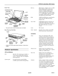
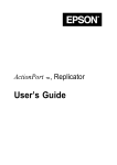
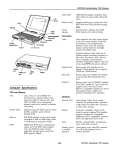
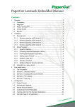
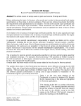
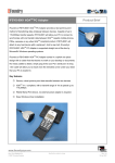
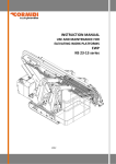
EPSON ActionNote 900 Series
Front View
Video RAM
1MB DRAM supports resolutions up to
640 X 480 in 256 colors on LCD and up to
1024 X 768 in 256 colors or 800 x 600 in
64K colors on external monitor
Cache
16KB internal write-back cache;
256KB external; both can be enabled/
disabled in Setup
Clock/calendar
Real-time clock, calendar, and CMOS
RAM; backed up by internal battery
Controllers
Video
Chips and Technology® 65545 video
controller; 32-bit local bus interface to
the microprocessor; supports enhanced
video modes on an external monitor;
supports resolutions from 640 X 480 in
256 colors on the LCD and up to 1024 X
768 in 256 colors on an external monitor;
automatic external monitor detection;
simultaneous display with LCD screen
using Fn F10 command or software
Diskette drive
Built-in super I/O controller for one
internal 3.5-inch diskette drive; supports
720KB and 1.44MB formats
Hard disk
Built-in super I/O controller has
interface to one 2.5-inch, IDE internal
hard disk drive; automatically
recognizes and configures drives up to
19 mm high that support the IDE or
EIDE interface
PC Card
Built-in Vadem® VG-468 controller for
two stacked slots; supports two Type I
or II cards, or one Type III; PCMCIA
version 2.01 and JEIDA 4.1 compatible;
supports low power and suspend
modes; supports hot insertion (including
ExCA® standards); register compatible
with Intel® 82365SL
Rear Panel and Left Side
security
keyboard or
mouse port
Notebook Specifications
CPU and Memory
CPU
5x86 QFP CPU on L2 cache
System speed
Fast and slow speed selectable in Setup
Memory
8MB RAM soldered on the system
board; expandable up to 24MB using a 4,
8, or 16MB memory expansion module.
ROM
128KB Flash ROM device containing the
system and video BIOS and Setup
program code. The BIOS is shadowed in
DRAM for faster access
daughterboard; CPU includes 16KB of
write-back unified data and instruction
cache and integrated math coprocessor
10/21/95
AN900-2
EPSON ActionNote 900 Series
Mass Storage
Interfaces
External VGA
Auto-sensing, 15-pin, D-sub, female
connector for analog monitor; supports
simultaneous display with LCD using
Fn F10 hot-key sequence or software
command
Parallel
Centronics® compatible; 25-pin,
D-sub, female connector; bidirectional
8-bit parallel; autodetects ECP or EPP
devices when connected and turned on
at system start-up
Serial
RS-232C, programmable, asynchronous,
9-pin, D-sub male connector, 16C550Ccompatible
External
keyboard/mouse
Auto-sensing, 6-pin, mini-DIN
connector for a PS/2type external
keyboard, keypad, or pointing device
Infrared
IrDA-compliant interface; up to
115.2 kbits/second to a distance of 3.3
feet (1 meter) within a 30° viewing angle;
can use COM1(3F8h) or COM2 (2F8h)
Speaker
Internal; automatically disabled when
line-out is used
Audio input and
output
Connectors for stereo line-in and lineout and for monaural microphone
Port replicator
Connector for optional ActionPort™
Replicator
Security
Connector for optional Kensington®
security device
Keyboard
85 keys; optional 101-key keyboard
compatible; embedded numeric keypad;
Fn key for hot key commands
ActionPoint
Touchpad
Built-in touchpad pointing device with
two buttons compatible with standard
PS/2 mouse driver software; can be
disabled in Setup
Volume
Control
Knob adjusts sound volume of internal
speaker and audio output
Hard disk drive
One removable internal IDE hard disk
drive, 2.5-inch form factor; maximum
height 19 mm; BIOS automatically
recognizes and configures drives that
support IDE or EIDE interface;
parameters for the supported drives are
as follows:
Diskette drive
Internal 3.5-inch diskette drive;
720KB or 1.44MB format
Setup Program
Stored in ROM; accessible by pressing
F8 at system startup; includes power
management utilities and password
protection
Software
One-time choice of MS-DOS and
Microsoft Windows™ or Window® 95;
Also pre-installed: Lotus® Smart Suite,®
NetCom™ NetCruiser,™ trial versions of
CompuServe,® PRODIGY,® America
Online,® and OAG® FlightDisk®; as well
as ARK Workspace®, Puma TranXit
infrared utility; SystemSoft drivers and
utilities for PC card slots; utilities for
video system, sound card, infrared port,
and touchpad. Online version of User’s
Guide and other manuals also installed
on the hard disk drive; refer to About
Your Software card for details on
EPSON’s support policy
LCD Screen
Screen type
Backlit
I Passive color
I
Resolutions
and colors
640 x 480,
I 256 colors
I
Diagonal
measurement,
active area
AN900-3
10/21/95
10.4 inches
EPSON ActionNote 900 Series
Infrared Specifications
Specification
Operating
Compatibility
IrDATM-compliant
COM
COM1
COM2 (default)
Operating Range
30° radius
Operating Distance
3.3 ft
(1m)
Speed
Up to 115.2 Kbps
Power Sources
AC Power Adapters
LED Panel
con
\ ’ ,
Name
Meaning
Power
Green-Computer is on
Flashing green-Very low battery; system is
about lo power down
Suspend
Green-Standby mode; press any key to
return to full power
Flashing green-Suspend mode; press
Suspend/Resume button to return to full power
9:
c!J
0
=
rl
Charge
Orange-battery is charging normally
Green-battery is fully charged
Flashing orange-battery is not installed
correctly or is damaged
Diskette
drive
Computer is accessing the diskette drive
Hard disk
drive
Computer is accessing the hard disk drive
Battery
Rechargeable 12 Volt NiMH battery;
current regulation by thermistor; battery
life with power savings, 4-6 hours.
Caution
Use only the adapters and replacement batteries designed for
use with the ActionNote 900 series (lightweight AC adapter
A882051, international AC adapter A882101, auto adapter
A882241. and battery A882291).
Environmental Requirements
El
PCMCIA
PC card is inserted
Non-operating
A
v
cl
1
-4° to 140° F
(-20° to 60° C)
Num Lock
Num Lock is on, which activates the
embedded numeric keypad
Caps
Lock
Caps Lock is on
Scroll
Lock
Scroll Lock is on
A
5% to 95%
Altitude
-200 to 12,000 ft
I (-67 to 4,000 m)
-200 to 30,000 ft
(-67 to 9,000 m)
Acoustical noise
35 dB at 1 meter
I (maximum)
N/A
I
Caution
When traveling by airplane, take the computer into the
passenger compartment to prevent it from being stored in an
unpressurized storage compartment. Avoid exposing the
computer to extreme changes in temperature.
Physical Dimensions
10/21/95
AN900-4
EPSON ActionNote 900 Series
Optional Equipment
Major Subassemblies
I
4 MB, 8MB or 16MB snap-in memory expansion module
I
1.2 GB user-removable hard disk drive
memory module
I Additional NiMH batteries
I
Extra AC adapter or international AC adapter
I
Adapter for an automobile cigarette lighter
LED panel audio/LED
card under panel
I External battery charger
I External keyboard
I External numeric keypad
I
PCMCIA Type I, II, and III cards including flash RAM,
SRAM, modem, fax/modem, LAN, and hard drive cards
I ActionPort Replicator
L2 cache board
I Portable CD-ROM player
I
IrDA transc&er
interface
Kensington MicroSaver Security Lock
board
I Carrying cases
Memory Module Installation
The computer comes with 8MB of memory soldered on the
system board. It includes a single memory module socket in
which you can install an additional 4, 8 or 16MB memory
module. Run the Setup program to check the amount of
memory installed.
System Board Components
C
J8
I
J9
J4
C
I
J14
C
PCMCIA SLOT
U4
FLOPPY DISK DRIVE
:
AN900-5
10/21/95
EPSON ActionNote 900 Series
Serial port connector (J2)
System board components
Pin Signal
Pin Signal
Pin Signal
1
Carder Detect 4
Data Terminal 7
Ready
Request to Send
2
Receive Data 5
Signal Ground 8
Clear to Send
3
Transmit Data 6
Data Set Ready
Ring indicator
9
VGA connectorfor an external monitor (J3)
Pin
Signal
Pin
Signal
Pin
Signal
1
Red
6
Ground
11
NC
2
Green
7
Ground
12
NC
3
Blue
8
Ground
13
Horizontal Sync
4
NC
9
NC
14
Vertical Sync
5
Ground
10
Ground
15
NC
Power converter board connector (22-pin male) (J17’)
Connector Pin Assignments
Parallel port connector (J1)
Pin No.
Signal Name
Pin No.
Signal Name
1
NC
14
AUTO FEED XT
2
Do
15
ERROR
3
D1
16
INIT
4
I
D2
I
17
A constant voltage from AC adapter
Power converter board connector (14-pin male) (J16)
SLCT IN
D3
I 18
GND
Pin No.
Signal Name
Description
D4
19
GND
1 to 4
VA
Constant voltage from AC adapter
7
D5
20
GND
5
CHGLED
Output pin to drive the orange LED
8
D6
21
GND
6
SWITCH
To power on DC/DC converter
9
D7
22
GND
7
PWRON
Reserved
10
ACK
23
GND
8
NC
No connection
11
BUSY
24
GND
9
NC
No connection
12
PE
25
PRT SEL
10
PWROFF
To power off DC/DC converter
13
SLCT
11 to 14
GND
Ground
5
6
I
I
10/21/95
AN900-6
EPSON ActionNote 900 Series
External keyboard/mouse connector (J7)
HDD IDE connector (J23)
Pin
Signal
Pin
Signal
Pin
Signal
1
AUX-DATA
3
GND
5
AUX-CLK
1
2
NC
4
+5 v
6
NC
2
3
Microphone connector (J8)
Pin
Signal
Pin
Signal
Pin
Signal
1
AGND
3
BMIC
5
MICIN
2
MICIN
4
BMIC
+
I
lrDA connector (J15)
Pin No.
Signal
Pin No.
Signal
1
TRIS
12
GND
2
GND
13
DSR2
3
PTS2
14
VCC5
4
VCC5
15
SPK
5
DCD2
16
MIC
6
SOUT2
17
SPK
7
DTR2
18
GND
1
Signal
1 GND
Signal Name
RESET DRV
21
GND
GND
22
IOWR
IDE D7
23
GND
4
GND
24
IORD
5
SD8
25
GND
6
SD6
26
IOCHRDY
7
SD9
27
IRQ14
8
SD5
28
IOCS16
17
SD14
37
VCC5
18
SD0
38
VCC5
19
SD15
I 39
20
GND
40
Pin
Signal
I Signal Name
I2
1 SPK
I
I Pin No.
I Signal Name
I
1
VCC5
11
GND
2
INDEX
12
WDATA
3
VCC5
13
GND
4
DR0
14
WGATE
5
VCC5
15
GND
6
DSKCHG
16
TRK0
7
MEDIA0
17
GND
8
MTR0
18
WRTPRT
9
DIR
19
RDATA
10
STEP
20
HDSEL
AN900-7
I
I GND
VCC5
Pin
Signal Pin
Signal
Pin
Signal
Pin
Signal
1
GND
MA10
37
MD16
55
NC
FDD connector (J22)
1 Pin No.
Signal Name
Memory module connector (J10)
Speaker connector (J18)
Pin
Pin No.
Pin No.
10/21/95
19
EPSON ActionNote 900 Series
10/21/95
AN900-8
EPSON ActionNote 900 Series
Main board connector to power converter (J17)
Pin Signal
Pin Signal
Pin Signal
Pin Signal
1
GND
7
DOCKON
13
19
ADPR
2
GND
8
SUSHDD
14
VCC5
20
DOCK PR
3
GND
9
CLKOFF
15
VCC3
21
DOCK PR
4
GND
10
DOCKPLG
16
12V
22
DCCK PR
5
SWON
11
ADPTR
17
VCC3
6
GND
12
VCC5
18
CHAR ID
VCC5
Touchpad connector (J19)
Pin Signal
Pin
Signal
Pin Signal
Pin
Signal
1
TBDIS
5
MCLK
9
TBDIS
13
MCLK
2
Z8PO0
6
NC
10
Z8PO0
14
NC
3
Z8PO1
7
GND
11
Z8PO1
15
GND
4
VCC5
8
MDATA
12
VCC5
18
MDATA
Internal keyboard connector (J20)
Pin
Signal
Pin
Signal
Pin
Signal
Pin
Signal
1
P37
4
P34
7
Z8PO1
10
P31
2
P36
5
P33
8
GND
11
P30
3
P35
6
Z8PO0
9
P32
I
Internal keyboard connector (J21)
Pin Signal
Pin Signal
1
SPDSEL0
4
NC
7
SPDSEL2
10
TKA3B
2
DAC2
5
TURBO
8
MA10
11
RESVGA
Pin Signal
Pin Signal
Daughterboard connector (JP2)
Pin Signal
Pin Signal
Pin Signal
Pin Signal
1
MA2
6
MA7
10
DTYWE
14
KRMWEA
2
MA3
7
MA8
11
KTOE
15
KRMWEB
3
MA4
8
MA9
12
KRMOEA
16
CLKOFF
4
MA5
9
DIRTY
13
KRMOEB
17
TKA3A
5
MA6
AN900-9
10/21/95
EPSON ActionNote 900 Series
Port Replicator connector (J6) (continued)
System Memory Map
00000H
640KB base memory
0A0000H
128KB reserved for graphics display area
0C0000H
Reserved
Hardware Interrupts
0D0000H
Reserved
0E0000H
48KB for VGA BIOS
0EA000H
Power Management Utility
0F0000H
64KB for system BIOS
100000H
Extended memory
FFE000H
Duplicated code assignment at address 0F0000
1
FFFFFFH
DMA Assignments
CPU Configuration Information
Switch
S1 CPU Type
Cyrix 5x86 QFP
daughterboard
Cyrix 5x86 PGA
S2 Speed
(Motherboard speed)
DC board voltage
(on DC board)
Description
1,
2,
3,
4,
ON
OFF
OFF
ON
settings for 5x86
QFP
1,
2,
3,
4,
ON
ON
OFF
ON
settings for 5x86
PGA
left
center
right
40MHz
33MHz
25MHz
left
center
right
4V
3.45V
3.3V
Channel
Device
DMA0
Available
DMA1
Sound Card
DMA2
Diskette Controller
DMA3
ECP
DMA4
Cascade for DMA CTRL #1
DMA5
Available
DMA6
Available
DMA7
Available
10/21/95
I
AN900-10
EPSON ActionNote 900 Series
Installation/Support Tips
System I/O Address Map
Hexadecimal Address
000-01F
DMA Controller 1
020-03F
interrupt Controller
040-05F
Timer/Counter
060-06F
Keyboard Controller
070-07F
RTC NMI
080-09F
DMA Page Register
0A0-0BF
Interrupt Controller 2
0C0-0DF
DMA Controller 2
0F0
Clear Math Coprocessor Busy
0F1
Reset Math Coprocessor
0F8-0FF
Math Coprocessor
100-1EF
Available
1F0-1F8
Hard Disk Drive
200-207
Game Port
208-277
Sound Card
278-27F
Parallel Port 2
2F6-2FF
Serial Port 2
300-31 F
Prototype Card
360-36F
Reserved
378-37F
Parallel Port 1
380-38F
SDLC Bisynohronous 2
3A0-3AF
Bisynchronous 1
3B0-3BF
Mono Display Printer Adapter
3C0-3CF
Reserved
3D0-3DF
Color/Graphics Monitor Adapter
3E0-3EF
Using Low Battery Save to HDD and Instant On
Device
The ActionNote 900 series hard disk drive is partitioned at
the factory so that these options can be used. A 26MB area
is set aside for the saved data; this ensures that there is
enough space for all memory configurations.
To prepare the hard disk drive, run the PHDISK utility,
located in the C:\PM directory. You also need to run this
utility if you upgrade your system memory. Type the
following command at the DOS prompt and press Enter:
PHDISk/CREATE
In Windows 3.1, when the computer is turned on after
using the Low Battery Save to HDD or Instant On options,
the PCMCIA services are not reinitialized. The computer
recognizes SRAM PC cards, but does not recognize most
other PC cards. You must reboot to reinitialize the services.
Using an External Monitor
PCMCIA Controller
3F0-3F7
Diskette Drive Controller
3F8-3FF
Serial Port 1
2F8-2FF
IrDA Port
If you install a new hard disk drive and want to use the
Low Battery Save to HDD or Instant On options, you need
to leave sufficient space on the disk unpartitioned. The
amount of space should equal the system memory plus
2MB. After you run FDISK to partition the drive, you need
to run the PHDISK utility to configure the storage space on
the drive.
I
I
When you connect an external monitor, make sure you turn it
on before you turn on the computer. The ActionNote
automatically detects the external monitor and displays data
on its screen. Press Fn F10 to switch your display from the
monitor to the LCD screen or to display on both screens
simultaneously. Resolutions up to 1024 x 768 in 256 colors
supported.
Using the ActionPoint Touchpad
I
If you use an external pointing device connected to the mouse
port, the touchpad is automatically disabled. If you want to
use the touchpad, turn the computer off and then on, and
touch the ActionPoint first
Using a Serial Mouse
If you connect a serial mouse, you must use the Setup
program to disable the built-in touchpad.
Using the IrDA Port
When communicating with another IrDA-equipped device,
such as a printer or computer, ensure that the IrDA ports are
within 3 feet, with no more than a 30-degree angle in a direct
line of sight with no obstructions. See the User’s Guide for
details.
AN900-11
10/21/95
EPSON ActionNote 900 Series
Information Reference List
Engineering Change Notices
None
Technical Information Bulletins
None
Product Support Bulletins
None
Related Documentation
400521900
EPSON ActionNote 900 Series User’s Guide
400526900
About Your Software
400527000
Choosing Your Operating System
PL-AN900S
EPSON ActionNote 900 Series Parts Price List
TM-AN900T
EPSON ActionNote 900 Series Service Manual
10/21/95
AN900-12
EPSON ActionNote 900 Series
AN900-13
10/21/95