1
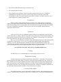
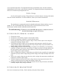
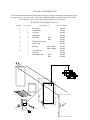
Henkel, Inc.
P.O. Box 1322
Hammond, LA
70404
(985) 345-2171
www.keenovens.com
Henkel, Inc.
P.O. Box 1322 * Hammond, Louisiana * 70404 * (985) 345-2171
www.keenovens.com
Model KHT-900 Oven
Installation Instructions & Repair Parts List
One Year Limited Warranty
Henkel, Inc. warrants its products against defects in material and workmanship. Henkel,
Inc. will either repair or replace without charge any properly installed product which fails
under normal operating conditions within one year from date of installation, provided it is
returned to our factory, transportation prepaid, and our inspection determined it to be
defective under the terms of this warranty. The warranty covers only equipment
manufactured by Henkel, Inc., and does not extend to transportation, installation, or
replacement charges at the buyers’ facility; nor does it apply to any other equipment of
another manufacturer used in conjunctions with Henkel, Inc. equipment. No other
warranty, expressed or implies exists beyond that included in this statement.
Keen Ovens
Model KHT-900
Specifications
Capacity
1000lbs. / 18" rods
Volts
240 V
Watts
6000 W
Thermostat
Proportional - Intergrated
Temperature
0ºF-999ºF
Insulation
4"(10.16cm) Mineral Wool
Interior Dimensions
18" X 19.3" X 36"
Net Weight
285 lbs.
Shipping Weight
305 lbs.
Shipping Dimensions
40" X 34" X 55"
Recommended Spare Parts
When it is critical to have continuous operation of this unit;
we suggest having the following spare parts on hand:
Heating Element Assembly
Contactor
General Information
The model KHT-900 is a high temperature oven designed for rebaking electrodes.
Temperatures range from 0º - 999º F. The diagonally compartmented shelf design allows
greater capacity with less oven weight. These units are constructed of steel, treated, and
then painted with a chemical resistant safety blue exterior finish and high temperature
aluminum interior finish. All models are Mercury free.
Safety Precautions
Read all instructions completely before attempting to operate this unit.
*** SAVE THESE SAFETY INSTRUCTIONS ***
To reduce the risk of electrical shock, fire, or personal injury follow the guidelines below:
•
Before connecting unit to a power source, be sure the voltage supplied is the same as that specified on
the name plate of the unit.
•
Check outlet to ensure proper grounding of the electrical cable. Have a licensed electrician check the
A/C power outlet if you are not sure.
•
Use this unit for its intended purpose as described by literature.
•
Make sure power cord is located so that it will not be stepped on, tripped over, or otherwise subjected
to stress of heat, oil, or sharp edges. Do not close doors on the cord.
•
To reduce the risk of damage to the electric plug and cord, disconnect by plug rather than by the cord.
•
Do not use this unit if cord or plug is in poor condition. If it has been exposed to weather or immersed
in water, have a qualified serviceman inspect and replace parts as necessary.
•
WARNING! NEVER HANDLE PLUG, CORD, OR UNIT WITH WET HANDS OR WHILE
STANDING IN WATER.
•
Use special care when moving heavily loaded units.
•
Do not store combustible material on or around the unit.
•
Do not operate this unit empty.
•
When using the unit at a distance where an extension cord becomes necessary, a 3-conductor
grounding cord of adequate size must be used for safety, and to prevent loss of power and
overheating. Use only a UL listed extension cord suitable for outdoor use. Make certain wire size is
large enough for A/C amperage rating of unit.
Installation
Remove wooden crating material from upper portion of oven. Pallet material is removed by
leaning oven slightly forward and backward, and removing bolts from underside using an adjustable or
socket wrench. When oven is free from pallet, place bolts back into oven legs for leveling. Oven should
be leveled with slight tilt to the back. Locate oven in an area free of flammable material and near
appropriate electrical source.
Operation
Load oven in an area free of combustible material and close to an appropriate electrical source.
(Check name plate for voltage.) Adjust leveling bolts on legs so that oven is level and tilted slightly to the
back. (Operator should read the enclosed “Controller User’s Manual” before placing oven in operation.)
Note: The controller is to be used in the “Proportional” mode.
Wire oven to a fused disconnect of proper voltage and amperage. Load oven with desired amount
of electrodes. Switch on power to oven. Set over temperature controller higher than temperature
controller’s set point. Adjust temperature controller set point to desired temperature. Refer to the
“Controller User’s Manual” for instructions in tuning controller. All units are supplies with a UL listed SJ
power cord and meet electrical code requirements when used with a grounded circuit.
***CAUTION: DO NOT USE ON D/C POWER SUPPLY!***
Venting
The KHT-900 oven is vented through two screened plugs at top rear of oven.
Temperature Setting
To adjust temperature set point press and hold the “Read Set PT.” Push button. The current set
point will appear in the digital display. Locate the “Set Point” knob beneath the door flap. Turn the “Set
Point” until the desired set point appears in the digital display. Release the push button. Digital display
will now read interior oven temperature. (Inserting a screwdriver in the set point knob and turning the
knob with the screwdriver may accelerate Set point adjustment.) Adjust over temperature controller to a
set point higher than temperature controller’s set point and press reset button.
Functional Description
These high temperature ovens are designed for rebaking electrodes. After the rebaking process is
complete, electrodes may be transferred to the job site, a holding oven, or stored in the high temperature
oven an optimum temperature. The diagonal shelf design accommodates 50 lb. electrode containers
eliminating the need to remove rods from the containers. The diagonal shelf design compartments also
allow air to circulate freely throughout the oven.
Guide to Storage
See the enclosed guide to storage. This guide may be used in the absence of storage information
from the electrode manufacturer. In critical situations, contact your electrode manufacturer.
Scheduled Maintenance
The manufacturer recommends that unit be unloaded and cleaned of debris and dust every six
months. It is also recommended that a temperature probe be placed inside the unit next to the
thermocouple, and the controller calibration checked at this time.
Troubleshooting: The Keen oven model KHT-900 requires a minimal amount of
electrical knowledge to repair if necessary.
IF OVEN FAILS TO OPERATE – NO HEAT
1. Check power source.
2. Check power cord continuity. Replace cord assembly if faulty.
3. Check over temperature controller’s set point and reset button.
4. Check output side of fuse block for proper voltage. If fuses are bad, inspect oven wiring and
components for damage. Replace fuses.
5. Check input and output voltages on over temperature and temperature controller for proper
voltage. If input voltage is not present, check wiring. If input voltage is present and there is no
output voltage, replace or repair controller.
6. If output voltage is present, check for voltage at contactor coil controlled by over temperature
controller. If voltage is not present, check wiring. If voltage is present at coil and contactor is in
the open position, replace contactor. If the contactor is in the closed position and there is no
output voltage present, replace contactor.
7. If the over temperature contactor is functioning, next check the relay operated by the temperature
controller for proper control voltage and proper load voltage on the input and output sides of the
relay.
8. If there is no control voltage present at the relay, check wiring to the temperature controller and
temperature controller output voltage.
9. If control voltage is present at relay, check voltage between relay output and common. If no
voltage is present between relay output and common, replace relay.
10. If voltage is present between relay output and common, check wiring to elements, and element
continuity. Replace faulty wiring or elements.
IF OVEN FAILS TO REACH SET POINT
One or more elements may be faulty. Check continuity and replace faulty elements.
Corrective Maintenance
CHANGING HEATING ELEMENTS
1. Disconnect oven from power source.
2. Remove back cover and insulation.
3. Remove electrical leads from elements and inspect leads for damage. When removing or
installing leads on elements, use a backup wrench.
4. From inside of oven, remove element cover. Unscrew element brackets, and remove elements
from oven.
5. Install and rewire elements, being sure all connections are tight and insulated.
CHANGING THE CONTROLLER
1. Disconnect from the power source and remove cover plate from control box.
2. Tag and remove leads from back of controller.
3. The controller is held in place by mounting brackets on either side of controller. From the rear,
loosen mounting bracket screws, remove mounting brackets and slide controller from control box.
4. To reinstall, slide controller into control box, attach mounting brackets and tighten set screws.
5. Replace electrical leads on controller terminals as per wiring diagram. Note: When attaching
thermocouple leads to controller, the negative lead wire has red insulation and the positive lead
wire has white insulation.
6. Check to be sure all electrical leads are on proper terminals and are secure. Replace control box
cover plate.
CHANGING THE CONTACTOR
1.
2.
3.
4.
5.
6.
Disconnect oven from power source.
Remove cover plate from control box.
Remove and tag electrical leads from contactor.
Unbolt and remove contactor from control box.
When replacing contactor, be sure it is of proper voltage and amperage.
Install new contactor and rewire as per wiring diagram. Check to be sure wiring is correct and
terminals are tight.
7. Replace cover plate on control box.
CALILBRATION INSTRUCTIONS
For calibration procedure refer to the “Controller User’s Manual”. When using a remote
thermometer to check oven temperature against controller display, be sure thermometer sensing probe is
placed next to controller thermocouple to achieve proper temperature reading.
KHT-900 ACCESSORIES LIST
** Please state model number and serial number and specify voltage and wattage when ordering repair
parts, spare parts, or accessory parts. All necessary attaching hardware is supplied with each part ordered.
(Item numbers refer to pictorial drawings below for repair parts.)
Model KHT-900 Repair Parts List
ITEM #
QUANTITY
DESCRIPTION
1
2
3
4
5
1
1
2
2
2
Door Latch
Grab Handle
Vent Plug
Handy Box
Pilot Light
6
7
8
1
1
6
9
1
1
1
Temperature Control
Power Cord
Element
240V/ 1000 W
480V/ 1000W
Cord Protector
Contactor
Solid State Relay
240 V
480 V
240 V
480 V
PART NUMBER
430110
430109
490108
301033
301085
301101
301001
301014
301026
301029
301041
301008
301089
301006
3
8
4
2
9
10
5
7
6
1