1
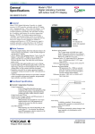
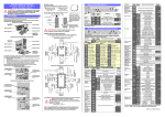
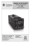
General Specifications Model UT350 Digital Indicating Controller GS 05D01D02-01E ■ General Model UT350 Digital Indicating Controller is a highly accurate 1/4DIN controller provided with universal input/ output. It has a large display for readings and excellent monitoring operability with the Auto/Man switching key. In addition, heating/cooling control, including PID control with auto-tuning, the “SUPER” overshoot suppressing function “SUPER” and the hunting suppressing function “SUPER2” are available as control functions, and a retransmission of variables and a 15 V DC loop power supply are also equipped as standard. A communication function or 24 V DC loop power supply is available optionally. As described above, the UT350 is a controller provided with higher functions and capability than conventional similar-size controllers. UT350 ■ Main Features Reference point = Measuring input range (0%) Reference point 1 Reference point 2 Measuring input range (100%) Reference point hysteresis = Fixed to 0.5% of the measured input range span. Reference deviation method: PID parameters (No. 4 PID) are selected when the deviation exceeds the reference deviation. This process takes precedence over the reference point method. Reference deviation = OFF or 0.1 to 100.0% of measured input range span • Extra-large digital display allows the indicated values to be read even from a long distance. LEDs of 20mm height are used for the process variable display. • Universal input and output enable users to set or change freely the type of measured inputs(thermocouple, RTD, or DCV), measurement range, type of control output(4 to 20 mA current, voltage pulse, or relay contact), from the front panel. • Parameters can be easily set using a personal computer. (“Parameter setting tool (model LL100)” sold separately is required.) • Various communication functions are provided. Communication is possible with personal computer, programmable logic controller, and other controllers. UT350E “E” indicates the model with expanded functions. Measuring innput range (100%) Reference deviation No.3PID Reference deviation ■ Functional Specifications Reference point2 ● Control Computation Functions Control computation: Can be selected from the following types: Continuous PID control, Time-proportional PID control, Heating/Cooling control (for heating/ cooling type only) or Relay ON/OFF control. Control cycle time: 250 ms Number of sets of target setpoints and PID parameters: 4 Target setpoint and PID selection: PID parameters are provided for every target setpoint and the set of PID parameters are selected at the same time that the setpoint number is selected. Zone PID selection: PID parameters are selected depending on the value of the PV. For selection, the reference point (PID parameter selection setpoint) or the reference deviation is used. Reference point method: The measuring input range is divided into a maximum of three zones with up to two reference points, and PID parameters are selected (No. 1 PID to No. 3 PID) for every zone. No.2PID Reference point1 No.1PID Measuring innput range (0%) Measured value (PV) Auto-tuning: Available as standard. If auto-tuning is operated, PID constants are automatically set (limit cycle method). “SUPER” function: Overshoots generated by abrupt changes in the target setpoint or by disturbances can be suppressed. “SUPER2” function: The function stabilizes the state of control that is unstable due to hunting, etc. without requiring any change in PID constans, when the load and/or gain varies greatly, or when there is a difference between the characteristics of temperature zones. GS 05D01D02-01E ©Copyright Feb. 2000 3rd Edition Jun. 2004 2 <<Contents>> <<Index>> Control Parameters Setting Range Proportional band = 0.1 to 999.9% 0.0 to 999.9% for heating/cooling control, 0.0% for ON/OFF control Integral time = 1 to 6,000s, or OFF (manual reset) Derivative time = 1 to 6,000s, or OFF Manual reset value = -5.0 to 105.0% of output range (functions when integral time is off.) ON/OFF control hysteresis = 0.0 to 100.0% of measured input range span (0.1 to 0.5% for heating/ cooling control) Setpoint rate-of-change setting = off, or 0.0 to 100.0%/h or min of measured input range span. A PV tracking function operates automatically when the setpoint is changed, the power is turned on, or the mode is changed from manual to automatic. Direct/reverse action: The output increase/decrease direction can be defined corresponding to a positive or negative deviation. For heating/cooling control, it is fixed; for the heating side output, reverse, for the cooling side output, direct. Anti-reset windup: When controller output is limited, normal integration is superseded by an anti-reset windup computation to suppress overintegration. Control output cycle time = 1 to 1000 s (for Timepropotional PID control) (the cooling side output cycle time is also the same when heating/cooling control is used). Preset output value = -5.0 to 105.0% of output range Output tracking: Whether the output bump is provided or not can be selected by changing the PID control mode. Output limiter Upper limit = Lower limit to 105.0% of output range Lower limit = -5.0% of output range to upper limit Heating/cooling dead band = -100.0 to 50.0% for output range ● Signal Computation Functions Measured input computation: Bias addition (-100.0 to 100.0% of measured input range span), and first-order lag filter (time constant off or 1 to 120 s) Contact input function: Target setpoint selection, Auto/Man operating mode switching, key lock parameter display/ non-display switching Target setpoint selection can be done for either a 2-setpoint or 4-setpoint selection. • If the 2-setpoint selection is set, Auto/Man mode switching can be used as well. • If the 4-setpoint selection is set, Auto/Man switching and key lock parameter display/nondisplay switching cannot be used together. If key lock parameter display/non-display switching is used, target setpoint selection and Auto/Man mode switching cannot be used. ● Alarm Functions Eighteen types of alarm functions are provided. The alarm status is indicated by the alarm lamp on the front panel. Also, three points among them can be output as relay contact outputs. Alarm types: PV high limit, PV low limit, Deviation high limit, Deviation low limit, Deenergized on deviation high limit, Deenergized on deviation low limit, Deviation high and low limits, High and low limits within deviation, Deenergized on PV high limit, Deenergized on PV low limit, SP high limit, SP low limit, Output high limit, Output low limit, Heater burnout alarm, sensor grounding alarm, Fault diagnostic alarm, FAIL output. Alarm output: 3 points. Any three points can be output as contact outputs among the above alarms. For heating/cooling control, if cooling side output is output as a relay contact, up to two alarm outputs can be used. Setting ranges for PV, deviation, setpoint and output alarms: PV/setpoint alarm: -100.0 to 100.0% of measured input range Deviation alarm: -100.0 to 100.0% of measured input range span Output alarm: -5.0 to 105.0% of output range Alarm hysteresis: 0.0 to 100.0% of measured input range span Delay timer: 0.00 to 99.59 (minute, second) An alarm is output when the delay timer expires after the alarm setpoint is reached. Setting for each alarm is possible. Stand-by action: Stand-by action can be set to make PV/ deviation alarm OFF during start-up or after SP change until SP reaches the normal region. Heater burnout alarm (optional): Two circuits incorporated A heater burnout alarm is output if the heater current consumption is the burnout detection value or less. This alarm can be used for Relay ON/OFF control or time-proportional PID control. Heater current setting range: 0.0 to 50.0 A Setting accuracy: ± 5% of span ± 1 digit Heater current detecting resolution: 0.5 A Time required until burnout detection is on: 0.2 s minimum burnout sensor model: CTL-6-S-H(URD Co. Ltd.) Sensor grounding alarm: An alarm is output after detecting a change in control output. If the moving average * of control output is out of the setting range (between the high and low limits of the on/off rate) in spite of the deviation being within a fixed range (on/off rate detection band) and control being in stable condition, the sensor is judged to be in a grounding condition. * Moving average refers to the average value for output values sampled (five times) in every cycle time. High- and low-limit setting range of on/off rate: -5.0 to 105.0% of output range All Rights Reserved. Copyright © 2000, Yokogawa Electric Corporation GS 05D01D02-01E 3rd Edition May.21,2004-00 3 <<Contents>> <<Index>> Detection band of on/off rate: 0.0 to 100.0% of measured input range span. Fault diagnostic alarm: Input burnout, A/D conversion error, thermocouple reference junction compensation error FAIL output: Software failure and/or hardware failure When in fail, control output, retransmission output and alarm output become 0% or OFF. ● Display and Operation Function PV display: In 4-digit digital display for engineering data Setpoint display: Various data, such as the setpoint (SP), are displayed by selection on the 4-digit digital display. Status indicating lamps: 3 alarm indicator lamps: AL1, AL2, AL3 3 setpoint number indicator lamps: SP2, SP3, SP4 (Go out when SP1 is selected.) MAN operation mode lamp: MAN (lit in MAN mode) Operation keys: 쑶and 쑴 keys: Increase or decrease setpoints and various parameters. SET/ENT key: Used for data setting or call-up/selection of various parameters A/M key: Switching of operation mode (Auto/Man) SELECT display: A panel where operating parameters that are frequently changed during operation can be selected and registered. For example, by registering the alarm -1 setpoint in the SELECT display, the setpoint can easily be displayed during operation. Security function: An operation-inhibiting mode using a password is provided. LED display unit (for PV) Status lamps Display PV, and error code when error is detected. Alarm(AL1, 2, 3), Manual(MAN). Setpoint No. (SP2, 3, 4) in use. Communication port for light loader Parameters are set via communication from a personal computer. Operational keys LED display unit (for SP) Display setpoint (SP), output value, and setting item/value of parameters. Increase/Decrease the setting data (쑶, 쑴) Select parameter/Enter the setting data (SET/ENT) A/M mode switching (A/M) All Rights Reserved. Copyright © 2000, Yokogawa Electric Corporation GS 05D01D02-01E 3rd Edition May.21,2004-00 4 <<Contents>> <<Index>> ● Communication Functions(optional) This controller has a communication function and can be connected to a personal computer, programmable logic controller or other GREEN series controllers. Communication protocol Computer link communication: Communication protocol with a personal computer. Ladder communication: Communication protocol with programmable logic controller. MODBUS communication: Communication protocol with a personal computer or PLC. Coordinated operation: Communication protocol to coordinated operation with two or more GREEN series controllers. The UT350 can be connected as a master station or a slave station. Communication interface Communication protocol: Computer link, ladder communication, MODBUS or coordinated operation. Standards: EIA RS485 Maximum number of connectable controllers: 31 GREEN series controllers Maximum communication distance: 1,200 m Communication method: Two-wire half duplex or four-wire half duplex, start-stop synchronization, nonprocedural. Communication rate: 600, 1200, 2400, 4800, or 9600 bps Examples of Communication System Configuration Diagram (1) Computer link communication (2) Ladder communication Personal computer PLC PV PV2 PV PV2 PV PV2 PV PV2 PV2 AL AL 1 2 3 REM 4 MAN1 SET/ENT AL 1 2 3 REM 4 MAN1 MAN2 STP CAS SET/ENT 1 2 3 REM 4 MAN1 MAN2 STP CAS A/M DISP PV PV2 PV PV2 PV PV2 PV AL 1 2 3 REM 4 MAN1 MAN2 STP CAS A/M SET/ENT AL 1 2 3 4 MAN2 STP CAS A/M DISP AL AL 1 2 3 REM 4 MAN1 MAN2 STP CAS REM MAN1 MAN2 STP CAS 1 2 3 4 AL 1 2 3 4 REM MAN1 MAN2 STP CAS REM MAN1 MAN2 STP CAS A/M DISP DISP SET/ENT A/M SET/ENT UT350/UT320 Digital indicating controller A/M DISP SET/ENT A/M DISP SET/ENT A/M DISP SET/ENT DISP UT350/UT320 Digital indicating controller (3) Coordinated operation PV2 PV AL 1 2 3 REM 4 MAN1 MAN2 STP CAS A/M SET/ENT PV2 DISP PV UP350 Program controller or UT350/UT320 Digital indicating controller PV2 AL PV PV2 AL 1 2 3 REM 4 MAN1 SET/ENT PV2 SET/ENT 1 2 3 REM 4 MAN1 MAN2 STP CAS MAN2 STP CAS A/M DISP PV AL 1 2 3 REM 4 MAN1 MAN2 STP CAS A/M DISP PV AL 1 2 3 REM 4 MAN1 MAN2 STP CAS A/M SET/ENT A/M DISP SET/ENT DISP UT350/UT320 Digital indicating controller All Rights Reserved. Copyright © 2000, Yokogawa Electric Corporation GS 05D01D02-01E 3rd Edition May.21,2004-00 5 <<Contents>> <<Index>> ■ Hardware Specifications Measured Input Signal Number of input points: 1 Input system: The types of input/measurement ranges can be set using key operation or software from a list of inputs. Input type, measurement ranges and measurement accuracy: Refer to the table below. Input Type Unspecified(when shipped from the factry) Thermocouple OFF K 1 2 3 J T 4 5 6 7 B S R N E L (DIN) U (DIN) W (DIN) Platinel 2 PR20-40 RTD Input range code W97Re3-W75Re25 JPt100 Pt100 Standard signal 0.4 to 2V 1 to 5V DC voltage 0 to 2V 0 to 10V -10 to 20mV 0 to 100mV Instrument range (˚C) Instrument range (˚F) Measurement accuracy*1 Set the data item PV input Type"IN" to the OFF option to leave the PV input type undefined. ±0.1% of instrument range ±1 digit for temperatures equal to or higher than 0 ˚C, ±0.2% of instrument range ±1 digit for temperatures below 0 ˚C -200 to 1370˚C -199.9 to 999.9˚C -199.9 to 500.0˚C -199.9 to 999.9˚C -300 to 2500˚F 0 to 2300˚F -199.9 to 999.9˚F -300 to 2300˚F -199.9 to 400.0˚C 0.0 to 400.0˚C 0 to 1800˚C -300 to 750˚F -199.9 to 750.0˚F 32 to 3300˚F 8 9 10 0 to 1700˚C 0 to 1700˚C -200 to 1300˚C 32 to 3100˚F 32 to 3100˚F -300 to 2400˚F 11 -199.9 to 999.9˚C -300 to 1800˚F 12 13 14 15 -199.9 to 900.0˚C -199.9 to 400.0˚C 0.0 to 400.0˚C 0 to 2300˚C -300 to 1300˚F -300 to 750˚F -199.9 to 750.0˚F 32 to 4200˚F 16 17 0 to 1390˚C 0 to 1900˚C 32 to 2500˚F 32 to 3400˚F ±0.1% of instrument range ±1 digit ±0.5% of instrument range ±1 digit for temperatures equal to or higher than 800˚C No guarantee of accuracy for temperatures below 800˚C ±0.2% of instrument range ±1 digit ±0.15% of instrument range ±1 digit for temperatures equal to or higher than 400 ˚C ±5% of instrument range ±1 digit for temperatures below 400 ˚C ±0.15% of instrument range ±1 digit ±0.1% of instrument range ±1 digit ±0.25% of instrument range ±1 digit for temperature below 0 ˚C ±0.1% of instrument range ±1 digit for temperatures equal to or higher than 0˚C ±0.2% of instrument range ±1 digit for temperatures below 0˚C ±0.2% of instrument range ±1 digit 18 0 to 2000˚C 32 to 3600˚F 30 -199.9 to 500.0˚C -199.9 to 999.9˚F ±0.1% of instrument range ±1 digit (Note 1) (Note 2) 31 35 36 -150.0 to 150.0˚C -199.9 to 850.0˚C -199.9 to 500.0˚C -199.9 to 300.0˚F -300 to 1560˚F -199.9 to 999.9˚F ±0.2% of instrument range ±1 digit (Note 1) ±0.1% of instrument range ±1 digit (Note 1) (Note 2) -199.9 to 300.0˚F ±0.2% of instrument range ±1 digit (Note 1) ±0.1% of instrument range ±1 digit 37 40 41 -150.0 to 150.0˚C 0.400 to 2.000 1.000 to 5.000 0.000 to 2.000 Scaling is enable in the following 4 range. -1999 to 9999 50 51 55 0.00 to10.00 -10.00 to 20.00 -199.9 to 999.9 -19.99 to 99.99 56 0.0 to 100.0 -1.999 to 9.999 The read-out range can be scaled between 1999 and 9999. *1: Performance in the standard operating conditon (at 23°C ±2°C, 55±10%RH, and 50/60Hz power frequency) *2: To receive a 4 to 20mA DC sgnal, select a standard signal of 1 to 5V DC and connect it to a 250 ohm resistor. This resistor is optional. Model & suffix code : X010-250-2 (resistor with M3.5 crimp-on terminal lugs) Note 1: The accuracy is ±0.3°C of instrument range ±1 digit for a temperature range from 0 to 100°C. Note 2: The accuracy is ±0.5°C of instrument range ± 1 digit for a temperature range from -100 to 0°C and 100 to 200°C. Sampling period: 250 ms Burnout detection: Functions with a thermocouple (TC), RTD, standard signal 0.4 to 2 V DC, and 1 to 5 V DC. Can be specified as upscale, downscale, and off. For standard signal, judged as burnout at 0.1 V or less. Input bias current: 0.05 µA (for TC/RTD b-terminal) Measuring current(RTD): about 0.13mA Input resistance: 1 MΩ or more for TC/mV input About 1 MΩ for DC voltage input All Rights Reserved. Copyright © 2000, Yokogawa Electric Corporation Allowable signal source resistance: 250 Ω or less; effect of permissible signal source resistance 0.1 µV/Ω or less for TC/mV input 2 k Ω or less; effect of permissible signal source resistance 0.01%/100 Ω or less for DC voltage input Allowable leadwire resistance: Max. of 150 Ω/wire (resistance in each of three wires must be equal) for RTD input However, 10 Ω/wire for a maximum range of -150.0 to 150.0°C. Effect of permissible leadwire resistance ± 0.1°C/10 Ω or less GS 05D01D02-01E 3rd Edition May.21,2004-00 6 <<Contents>> <<Index>> Allowable input voltage: ± 10 V DC for TC/mV/RTD input ± 20 V DC for DC voltage input Noise rejection ratio: Normal mode 40 dB (50/60 Hz) or more Common mode 120 dB (50/60 Hz) or more Reference-junction compensation error: ± 1.0°C (15 to 35°C), ± 1.5°C (0 to 15°C, 35 to 50°C) Applicable standards: JIS, IEC, or DIN(ITS-90) for TC and RTD 24V DC Loop Power Supply for Sensor The controller supplies power to a two-wire transmitter. Place a resistor (10 to 250Ω) between the controller and the transmitter, convert a current signal to a voltage signal, and read it from the PV input. 21.6 to 28.0 V DC, maximum supply current is about 30mA (only for models with 24V DC loop power supply). ■24 V DC Power Supply Wiring to Two-wire Sensor 12 External resistor 250Ω (Note) Two-wire transmitter PV input 1 to 5 V DC signal 13 21 4-20mADC 22 Loop power supply 21.6 to 28.0 V DC Note: Connecting a 250 Ω resistor to the termanals is optional. Model: X010-250-2 (resistor with M3.5 crimp-on terminal lugs) Voltage pulse output Number of output points: 1 or 2 (2 for heating/cooling type), switched between voltage pulse output and current output. Output signal: On voltage = 12 V DC or more (load resistance of 600 Ω or more; current on short-circuiting about 30 mA) Off voltage = 0.1 V DC or less Resolution: 10 ms Relay contact output Number of output points: 1 or 2 (2 for heating/cooling type) Output signal: Three terminals for NC, NO, and Common transfer-contact Contact rating: 250 V AC, 3 A or 30 V DC, 3A (resistive load) Resolution: 10 ms Contact Inputs Usage: Target setpoint selection, Auto/Man mode switching, or Key lock parameter display/nondisplay switching Number of input points: 2 Input type: Non-voltage contact input or transistor open collector input Input contact rating: 12 V DC, 10 mA or more (for nonvoltage contact input) On/off determination: For non-voltage contact input, ON = contact resistance of 1 kΩ or less, OFF = contact resistance of 20 kΩ or more. For transistor contact input, ON = 2 V or less, OFF = leakage current of 100 µA or less. Minimum retention time for status detection: about 1 second Contact Outputs Retransmission Output Either PV, target setpoint, or control output is output. Either the retransmission output or the 15V DC loop power supply can be used. Number of output points: 1 Output signal: 4 to 20 mA DC Load resistance: 600 Ω or less Output accuracy: ± 0.3% of span * Performance in the standard operating conditions (at 23± 2°C, 55± 10% RH, and 50/ 60 Hz power frequency) 15V DC loop power supply: Supply voltage is 14.5 to 18.0 V DC. Maximum supply current is about 21 mA (with a protection circuit for a field short-circuit). Control Outputs The control output is of a universal scheme and can be selected from the following types of outputs. In the case of heating/cooling control, it is also selectable from these outputs. However, if the cooling side output is a relay contact output, the alarm-3 cannot be used, and similarly if the cooling side output is a voltage pulse or current output, the retransmission output/15 V DC sensor power supply cannot be used. Current output Number of output points: 1 or 2 (2 for heating/cooling type), switched between voltage pulse output and current output. Output signal: 4 to 20 mA Load resistance: 600 Ω or less Output accuracy: ±0.3% of span * Performance in the standard operating conditions (at 23± 2°C, 55± 10% RH, and 50/60 Hz power frequency) All Rights Reserved. Copyright © 2000, Yokogawa Electric Corporation Usage: Alarm output, FAIL output, and others Number of relay contact output points: 3 Relay contact rating: 240 V AC, 1 A or 30 V DC, 1 A (COM terminal is common for every contact output.) ● Display Specifications PV display: 4-digit, 7-segment red LED; character height 20 mm Setpoint display: 4-digit, 7-segment red LED; character height 9.3 mm Status indicating lamps: LEDs ● Conformance to Safety and EMC Standards Safety:Compliant with IEC/EN61010-1: 2001, approved by CSA1010, approved by UL508. Installation category : CAT. II (IEC/EN61010, CSA1010) Pollution degree : 2 (IEC/ EN61010, CSA1010) Measurement category : I (CAT. I : IEC/ EN61010) Rated measurement input voltage : 10V DC max.(across terminals), 300V AC max.(across ground) Rated transient overvoltage : 1500V (Note) Note : It is a value on the safety standard which is assumed by IEC/EN61010-1 in measurement category I, and is not the value which guarantees an apparatus performance. GS 05D01D02-01E 3rd Edition May.21,2004-00 7 <<Contents>> <<Index>> EMC standards: Complies with EN61326. The instrument continues to operate at a measuring accuracy of within ±20% of the range during tests. ● Construction, Mounting, and Wiring Construction: Dust-proof and Drip-proof front panel conforming to IP55. For side-by-side close installation, the controller loses its dust-proof and drip-proof protection. Material: ABS resin and polycarbonate Case color: Black Weight: Approx. 1 kg or less External dimensions: 96 (width) × 96 (height) × 100 (depth) mm Mounting : Direct panel mounting; mounting bracket, one each for upper and lower mounting +0.8 Panel cutout dimensions: 92 +0.8 0 (width) × 92 0 (height) mm Mounting attitude: Up to 30 degrees above the horizontal. No downward tilting allowed. Wiring: M3.5 (ISO 3.5 mm) screw terminals (signal wiring and power/ground wiring as well) ● Power Supply Specifications and Isolation Power supply: Rated at 100 to 240 V AC (±10%), 50/60 Hz Power consumption: MAX. 20 VA (MAX. 8.0 W) Internal fuse rating: 250 VAC, 1.6A time-lug fuse Memory back-up: Non-volatile memory (Service life approx. 100,000 times of writings) Withstanding voltage: 1500 V AC for 1 minute between primary and secondary terminals. (Note) 1500 V AC for 1 minute between primary and ground terminals. (Note) 1500 V AC for 1 minute between ground and secondary terminals. 500VAC for 1minute between two secondary terminals. Primary terminals = Power and relay output terminals Secondary terminals = Analog I/O signal terminals, voltage pulse output terminals, contact input terminals Note. The withstanding voltage is specified as 2300V AC perminute to provide a margin of safety. Isolation resistance: 20 MΩ or more when 500 V DC voltage is applied between the power terminals and ground terminal. Grounding: Class D grounding (grounding resistance of 100 Ω or less) All Rights Reserved. Copyright © 2000, Yokogawa Electric Corporation ● Isolation specifications: Measured input terminal: Isolated from other I/O terminals. Not isolated from internal circuits. 15 V DC loop power supply terminals: Not isolated from 4-20mA analog output and voltage pulse control output. Isolated from other I/O terminals and internal circuit. 24 V DC loop power supply terminals: Isolated from other I/O terminals and internal circuit. Control output (current or voltage pulse) and retransmission terminals: Not isolated between control output terminals and retransmission output terminals. Isolated from other I/O terminals and internal circuits. Relay contact control output terminals: Isolated from other I/O terminals and internal circuits. Contact input terminals: Not isolated from other contact input terminals mutually, and communication terminals. Isolated from other I/O terminals and internal circuits. Relay contact alarm output terminals: Isolated from other I/O terminals and internal circuits. RS-485 communication terminals: Not isolated from contact input terminals. Isolated from other I/O terminals and internal circuits. Power supply terminals: Isolated from other I/O terminals, ground terminal, and internal circuits. Ground terminal: Isolated from other I/O terminals, power terminals, and internal circuits. ● Environmental Conditions Normal operating conditions: Ambient temperature: 0 to 50°C (40°C or less for mounting of instruments side-by-side) Ambient temperature change limit: 10°C /h or less Ambient humidity: 20 to 90% RH (no condensing) Magnetic field: 400 A/m or less Continuous vibration (5 to 14 Hz): Peak-to-peak amplitude of 1.2 mm or less Continuous vibration (14 to 150 Hz): 4.9 m/s2 or less Short-period vibration: 14.7 m/s2, 15s or less Shock: 147 m/s2 or less, 11 ms Installation altitude: 2,000 m or less above sea level Warm-up time 30 minutes or more Transportation and storage conditions: Temperature: -25 to 70°C Temperature change limit: 20°C /h or less Humidity: 5 to 95% RH Effects of operating conditions Effect of ambient temperature: For voltage or TC inputs: Whichever is greater, ± 1µV/°C or ±0.01% of F.S./°C For RTD inputs: ±0.05°C/°C (ambient temperature) or less for RTD input For analog output: ±0.05% of F.S./°C or less Effect of power supply fluctuation (within rated voltage range): For analog input: Equal to or less than whichever is greater, ± 1 µV/10 V or ± 0.01% of F.S./10 V For analog output: ±0.05% of F.S./10 V or less GS 05D01D02-01E 3rd Edition May.21,2004-00 8 <<Contents>> <<Index>> ■ Function Block Diagram for Standard Type PV input terminals 11 , 12 and 13 Communication terminals 23 to 27 INPUT RS485 (when parameter DIS=1) Contact input DI1 DI2 Input selection Unit selection Input range conversion Input bias Input filter SP.NO Target setpoints 1 to 4 REMOTE SP.NO=0 LOCAL SP.NO=1 to 4 Target setpoint ramp-rate function Manual operation Control computation MAN A/M AUTO AUTO (ON)/MAN (OFF) switching Preset output Output limiter STOP RUN *1 24 V loop power supply 15 V loop power supply OT Retransmission output Control output LPS OUTPUT1 Terminals 21 and 22 Current or pulse terminals 16 and 17 OUTPUT1 Relay terminals 1 , 2 and 3 Alarm function RET OUTPUT2 /RET DO1 DO2 DO3 Alarm 1 Alarm 2 Alarm 3 Current terminals 14 and 15 *1: If the setup parameter DIS (DI function selection) is set to “4”, when the contact input 2 is ON (stop state), that controller outputs the preset output value. Terminal Parameter Function Analog signal Contact signal Front panel key Legend All Rights Reserved. Copyright © 2000, Yokogawa Electric Corporation GS 05D01D02-01E 3rd Edition May.21,2004-00 9 <<Contents>> <<Index>> ■ Function Block Diagram for Heating/Cooling Type PV input terminals 11 , 12 and 13 Communication terminals 23 to 27 PV INPUT RS485 (when parameter DIS=1) Contact input DI1 DI2 Input selection Unit selection Input range conversion Input bias Input filter SP.NO Target setpoints 1 to 4 REMOTE SP.NO=0 LOCAL SP.NO=1 to 4 Target setpoint ramp-rate function Manual operation Control computation MAN A/M AUTO AUTO (ON)/MAN (OFF) switching Heating/cooling computation Cooling-side output limiter Heating-side output limiter Heating-side preset output *1 *1 OT 15 V loop power supply OT Heating-side output Cooling-side preset output Retransmission output Cooling-side output Alarm function RET DO3 OUTPUT1 Current or pulse terminals 16 and 17 OUTPUT1 OUTPUT2 DO1 OUTPUT2 /RET Relay DO2 Alarm 1 Alarm 2 Relay Current or pulse terminals terminals 1 , 2 and 3 14 and 15 Current terminals 14 and 15 *1: If the setup parameter DIS (DI function selection) is set to “4”, *1: when If the setup parameter selection) is set to “4”, the contact input DIS 2 is (DI ONfunction (stop state), that controller outputs the preset output value. when the contact input 2 is ON (stop state), that controller outputs the preset output value. Terminal Parameter Function Analog signal Contact signal Front panel key Legend All Rights Reserved. Copyright © 2000, Yokogawa Electric Corporation GS 05D01D02-01E 3rd Edition May.21,2004-00 All Rights Reserved. Copyright © 2000, Yokogawa Electric Corporation 10 9 8 GS 05D01D02-01E CT CT 30 28 29 COM CT2 CT1 Heater current detection input 30 29 20 19 18 17 16 15 17 - 16 + 4-20 mA DC, voltage pulse (12 V) Control output Current/voltage pulse output 21.6-28.0VDC (30 mA DC max.) Common No function No function Common AUTO when DI2=ON MAN when DI2=OFF 2.SP when DI1=ON 1.SP when DI1=OFF OT=1 Time proportional control Voltage pulse output (terminals 16 and 17 ) Time proportional control Relay output (terminals 1 , 2 and 3 ) OT=2 Current output (terminals 16 and 17 ) OT=3 Common DI2 OFF OFF ON ON DI1 OFF ON OFF ON On-off control Relay output (terminals 1 , 2 and 3 ) Common No function When DIS=2 When DIS=3 switching target Hides the LOCK parameter when DI1=ON. When SP 1 to 4: Shows the LOCK parameter when DI1=OFF. 1.SP2.SP3.SP 4.SP Correspondence between parameter OT and control output types OT=0 (factory-shipped setting) Note:Select this option from the OT parameter. 13 - 12 + TC input 4-20 mA DC 15 - 14 + 14.5-18.0VDC (21 mA DC max.) 15 V DC loop power supply 15 - 14 + Retransmission output 13 - 12 + mV/V input 13 B 12 b 11 A RTD input UT Load resistance: 600 Ω or less +5V COM DI2 DI1 Contact rating: 12 V DC, 10 mA or more COM 20 DI2 18 +5V Transistor contact 20 18 19 Note: External Contact Input If the power is turned on when the external contact input is OFF, the mode (SP.NO or A/M) existing before the power is turned off will be continued. (except for RUN/STOP) Common STOP when DI2=ON RUN when DI2=OFF Contact * If 15 V DC loop power supply is used, retransmission output cannot be used. 2.SP when DI1=ON DI1 19 1.SP when DI1=OFF When DIS=4 250 Ω 4-20mA Note: Connecting a 250 Ω resistor to the terminals is optional. Model: X010-250-2 (resistor with M3.5 crimp-on terminal lugs) 13 - 12 + set the PV input type to 1-5 V DC (setpoint “41”). * When receiving 4-20 mA DC current signals, 䊏 Receiving 4-20 mA DC Current Signals with the Controller * PV retransmission is configured at factory before shipment. PV input * Not configured at factory before shipment Correspondence between parameter DIS and external contact input functions When DIS=OFF When DIS=1 (Factory-shipped setting) * OT is a setup parameter. You can change the settings of the parameter OT to change the control output type. * This wiring is only possible for a controller with a heater burnout alarm. 10 9 28 27 7 8 26 6 25 5 14 13 12 11 22 - 21 + * DIS is a setup parameter. Changing DIS setpoint allows you to change the function of external contact input. Before carrying out wiring, turn off the power to the controller and check that cables to be connected are not alive with a tester or the like because there is a possibility of electric shock. CAUTION Allowable range: 100 to 240 V AC (10%) (free voltage) 50/60 Hz shared N L Power supply Power supply 23 24 3 COM 7 Common Relay contact rating: 240 V AC, 1 A 30 V DC, 1 A (resistance load) Relay 4 22 AL3 4 Alarm-3 output 21 1 2 AL2 5 Alarm-2 output UT SG AL1 6 27 RDA(-) Alarm-1 output Alarm output 26 25 RDB(+) Note: Select this option from * Wiring can only be carried the OT parameter. RS-485 communication * Wiring can only be carried out out for controllers with * Time proportional PID for controllers with 24 V DC loop power supply. relay contact output is communication functions. 24 V DC loop configured at factory 23 SDB(+) Maximum baud rate: 9600 bps power supply before shipment. 24 SDA(-) Contact rating: 250 V AC, 3 A 30 V DC, 3 A (resistance load) 2 3 NO 1 COM NC Relay contact output Control output ■ Standard Type, Terminal Arrangements <<Contents>> <<Index>> 10 3rd Edition May.21,2004-00 2 3 NO COM * Time proportional PID relay contact output is configured at factory before shipment. * Available if 4, 7 or 10 is set in the OT (Control Output Type) setup parameter. AL1 6 Relay UT All Rights Reserved. Copyright © 2000, Yokogawa Electric Corporation 10 9 8 GS 05D01D02-01E CT CT 30 28 29 COM CT2 CT1 Heater current detection input 26 22 23 24 25 26 27 28 3 4 5 6 7 8 10 30 29 21 SG RDA(-) 1 27 2 9 for controllers with communication functions. Maximum baud rate: 9600 bps 11 20 19 18 17 16 15 14 13 12 No function Common No function Common AUTO when DI2=ON MAN when DI2=OFF 2.SP when DI1=ON 1.SP when DI1=OFF Heating side: Voltage pulse output (terminals 16 and 17 ) Cooling side: Relay output (terminals 4 and 7 ) Heating side: Relay output (terminals 1 , 2 and 3 ) Cooling side: Relay output (terminals 4 and 7 ) Heating side: Current output (terminals 16 and 17 ) Cooling side: Relay output (terminals 4 and 7 ) OT=6 RTD input Common DI2 OFF OFF ON ON DI1 OFF ON OFF ON OT=7 Heating side: Relay output (terminals 1 , 2 and 3 ) Cooling side: Voltage pulse output (terminals 14 and 15 ) OT=8 Heating side: Voltage pulse output (terminals 16 and 17 ) Cooling side: Voltage pulse output (terminals 14 and 15 ) 4-20 mA DC 15 - 14 + 4-20 mA DC, voltage pulse (12 V) Cooling-side control output 15 - 14 + Retransmission output When DIS=4 UT Common STOP when DI2=ON RUN when DI2=OFF 13 - 12 + 250 Ω 4-20mA set the PV input type to 1-5 V DC (setpoint “41”). Note: Connecting a 250 Ω resistor to the terminals is optional. Model: X010-250-2 (resistor with M3.5 crimp-on terminal lugs) Heating side: Current output (terminals 16 and 17 ) Cooling side: Voltage pulse output (terminals 14 and 15 ) 14.5-18.0VDC (21 mA DC max.) Contact +5V +5V COM DI2 DI1 OT=10 Heating side: Relay output (terminals 1 , 2 and 3 ) Cooling side: Current output (terminals 14 and 15 ) OT=11 Heating side: Current output (terminals 16 and 17 ) Cooling side: Current output (terminals 14 and 15 ) OT=12 Note: External Contact Input If the power is turned on when the external contact input is OFF, the mode (SP.NO or A/M) existing before the power is turned off will be continued. (except for RUN/STOP) Heating side: Voltage pulse output (terminals 16 and 17 ) Cooling side: Current output (terminals 14 and 15 ) 20 18 19 Transistor contact * The retransmission output and 15 V DC loop power supply are not available if the cooling-side control output is set to “continuous output” and “voltage pulse output.” * If 15 V DC loop power supply is used, retransmission output cannot be used. 15 - 14 + 15 V DC loop power supply Contact rating: 12 V DC, 10 mA or more COM 20 DI2 18 2.SP when DI1=ON DI1 19 1.SP when DI1=OFF OT=9 䊏 Receiving 4-20 mA DC Current Signals with the Controller * When receiving 4-20 mA DC current signals, * PV retransmission is configured at factory before shipment. 13 - 12 + mV/V input 13 B 12 b 11 A Correspondence between parameter OT and heating-side/cooling-side output types Common No function When DIS=2 When DIS=3 switching target Hides the LOCK parameter when DI1=ON. When SP 1 to 4: Shows the LOCK parameter when DI1=OFF. 1.SP2.SP3.SP 4.SP The control output types, “relay output” and “voltage pulse output” shown in the table above refer to those of time proportional control. To change the type to a relay output for on-off control, select “Relay Terminals” and change the setpoint of the proportional band to “0.” OT=5 OT=4 (factory-shipped setting) 17 - voltage pulse (12 V) Heating-side control output * Available if 5, 6, 8, 9, 11 Current/voltage or 12 is set in the OT pulse output (Control Output Type) setup parameter. 16 + 4-20 mA DC, 13 - 12 + TC input PV input * Not configured at factory before shipment Correspondence between parameter DIS and external contact input functions When DIS=OFF When DIS=1 (Factory-shipped setting) * OT is a setup parameter. You can change the settings of the parameter OT to change the control output type. * This wiring is only possible for a controller with a heater burnout alarm. SDA(-) 25 RDB(+) 24 23 SDB(+) RS-485 communication * Wiring can only be carried out * DIS is a setup parameter. Changing DIS setpoint allows you to change the function of external contact input. Before carrying out wiring, turn off the power to the controller and check that cables to be connected are not alive with a tester or the like because there is a possibility of electric shock. CAUTION Allowable range: 100 to 240 V AC (10%) (free voltage) 50/60 Hz shared N L Power supply Power supply Note: The cooling-side control output is selected if 4, 5 or 6 is set in the OT (Control Output Type) setup parameter. The alarm-3 output is not available. The controller is factory-set to the cooling-side control output (time proportional PID relay contact output). Relay contact rating: 240 V AC, 1 A 30 V DC, 1 A (resistance load) AL2 5 Alarm-3 output or cooling-side control AL3 4 output (Note) COM 7 Common Alarm-2 output Alarm-1 output Alarm output/cooling-side control output Contact rating: 250 V AC, 3 A 30 V DC, 3 A (resistance load) 1 NC Relay contact output Heating-side control output ■ Heating/Cooling Type, Terminal Arrangements <<Contents>> <<Index>> 11 3rd Edition May.21,2004-00 12 <<Contents>> <<Index>> ■ External Dimensions and Panel Cutout Dimensions Unit: mm Large bracket 96 91.8 100 112 11 96 Small bracket 1 to 10 mm (Panel thickness) General installation Side-by-side close installation [(N-1)96+92] +0.8 0 92 +0.8 0 117 min. (53) 92 145 min. +0.8 0 92 +0.8 0 "N" stands for the number of controllers to be installed. However, the measured value applies if N 5. (25) ■ Model and Suffix codes Model Suffix Code UT350 Type Optional functions Description Digital indicating controller (provided with retransmission output and 15 V DC loop power supply as standard) -0 -2 -3 Standard type Heating/cooling type Standard type (with 24 V DC loop power supply) 0 1 2 None With communication, Heater burnout alarm With heater burnout alarm Standard Accessories: Brackets (mounting hardware), unit label, User’s Manuals, and User’s Manual (reference) (CD-ROM version) ■ Items to be specified when ordering Model and suffix codes, necessary/unnecessary of User’s Manual or QIC. All Rights Reserved. Copyright © 2000, Yokogawa Electric Corporation GS 05D01D02-01E 3rd Edition May.21,2004-00 K4 Series 100 mm Strip Chart Recorders K4 Series 4" (100 mm) Continuous Trace and Multipoint Trace Strip Chart Recorders • • • • • • • Up to Four Pens for Continuous Traces Up to Six Inputs for Dot Traces Compact Size High Reliability Memory Card / PC Configuration Option Math, Counters, Timers Option Communications Option Recorders optional optional K4 Series strip chart recorders offer a full family of products from a single pen model K4CA to the full featured K4MB. Introduction Barber-Colman K4 Series Strip Chart Recorders are available with continuous trace writing pens (up to four) or a multipoint printhead that will provide dot printed traces for up to six inputs. Both the continuous and multipoint trace models are available with either an analog display or a digital display. In addition, the K4 is available with both digital display and segment bar display. This model also offers several advanced features such as memory card reader, math capabilities, totalizers, timers and counters, and serial communications. The K4 is housed in a compact case that extends less than 9-1/2" behind the mounting panel. It uses 100 mm x 16 m long (4" x 52-1/2 feet long) fanfold paper that is easily accessible from the front door. Contactless Feedback All K4 models use a state-of-the-art optical feedback system with brushless motors. This ensures that the combined motor and feedback system have high reliability and an excellent immunity to electromagnetic interference common to many switching cabinets. Input Card Technology Custom chips form the basis of a configurable, high accuracy, isolated input system. Auto calibration provides improved accuracy and stability with long-term calibration free service. By using second order Delta-Sigma modulators, each input is continuously sampled to provide integrated values for the measured variable. Data acquisition is updated regularly by digitally interrogating the variables through optical isolators. Each channel has its own measuring circuit to ensure high sample accuracy and fast input response. Wide Range of Models The line-up of K4 recorders includes: Model K4CA – Model K4MA – Model K4CD – Model K4MD – Model K4CB – Model K4MB – Continuous Trace Recorder with Analog Display Multipoint Trace Recorder with Analog Display Continuous Trace Recorder with Digital Display Multipoint Trace Recorder with Digital Display Continuous Trace Recorder with Digital Display and Segment Bar Multipoint Trace Recorder with Digital Display and Segment Bar Models K4XA and K4XD are configured at the factory to the specifications on your order and are ready for immediate use. Model K4XB is configurable from the front panel which makes it the ideal instrument for applications where configuration needs to be regularly modified. 1250-DB-100-0-00 Barber-Colman Company, Loves Park, IL Page 318 of 398 K4 Series 100 mm Strip Chart Recorders Ordering Information (continued) Model K4XB Recorder B - MODEL K 4 Field No. 1 2 3 4 5 6 Recorders Fields 1, 2, 3, 4. BASE MODEL K4CB - 4", continuous, bargraph/digital display K4MB - 4", multipoint, bargraph/digital display Field 5. NUMBER OF PENS Model K4MB 0 - None. Multipoint model Model K4CB 1 - One trace pen 2 - Two trace pens 3 - Three trace pens 4 - Four trace pens 5 - One trace pen with annotating pen 6 - Two trace pens with annotating pen 7 - Three trace pens with annotating pen 8 - Four trace pens with annotating pen Note: Annotating pen required if you want to print the time, date and channel information on the chart. Field 6. INPUTS Model K4CB 0 - Four fixed Inputs Model K4MB 2 - Two 3 - Three 6 - Six Fields 7, 8, 9, 10. OPTION CARDS Four cards maximum. 0 - None 1 - Normally open (four relay outputs) 2 - Normally closed (four relay outputs) 3 - SPDT, Form C (four relay outputs) 4 - Analog retransmission (two outputs; two cards maximum) 5 - Contact inputs (six inputs; one card maximum) Field 11. MATH 0 - None 1 - Level 1 2 - Level 2 3 - Totalizers, timers, counters 4 - Level 1, plus totalizers, timers, counters 5 - Level 2, plus totalizers, timers, counters Field 12. TRANSDUCER POWER SUPPLY 0 - None 3 - Three channel 6 - Six channel 1250-DB-100-0-00 7 8 9 10 11 12 13 14 15 Field 13. MEMORY CARD / COMMUNICATIONS 0 - None R - Reader only (configuration storage) 1 - Reader and 128K card (configuration storage) 2 - Reader and 512K card (configuration storage) 3 - Reader and 2M card (configuration storage) 4 - Serial communications only 5 - Serial communications, reader and 2M card 6 - Reader only (ASCII storage w/configuration) 7 - Reader and 512K card (ASCII storage with configuration) 8 - Reader and 2M card (ASCII storage with configuration) 9 - Reader, 2M card (ASCII w/config) and serial communications Field 14. CHART ILLUMINATION/ PEN OFFSET COMPENSATION 0 - No 1 - Chart illumination Model K4CB only 4 - Pen offset compensation 5 - Chart illumination and pen offset Field 15. SPECIALS 0 - None 1 - Certified calibration 2 - CE (European Community) approval 3 - Custom messages (20 messages) 4 - CSA testing/labeling 5 - Option codes 1, 2 (Cert. cal. and CE aproval) 6 - Option codes 1, 3 7 - Option codes 1, 4 8 - Option codes 2, 3 9 - Option codes 2, 4 A - Option codes 3, 4 B - Option codes 1, 2, 3 C - Option codes 1, 2, 4 D - Option codes 1, 3, 4 E - Option codes 2, 3, 4 F - Option codes 1, 2, 3, 4 Shunts and attenutators to be ordered separately. Barber-Colman Company, Loves Park, IL Page 320 of 398 AL3000 SERIES 100MM CHART MULTI-POINT TYPE HYBRID RECORDER MODEL AL3 7 5 - AL3000 series conforming to CE, UL and CSA are 100mm multi-point type hybrid recorders with a simultaneous display of multi-channel data, bargraph display, alarm display/printing and other unique features. Software packages of "KIDS" for data processing of measured values and “PASS” for programming parameters are available. FEATURES y Simultaneous multipoint data digital displays of y Communications interface (option) RS-232C, RS-422A or RS-485 with MODBUS protocol for easy configuration with your personal computer Simultaneous digital display of 6 points allows measured data to be viewed at a glance. y Clear trend and digital printings y Universal input Cassette type wire-dotting system 6-color ink ribbon for clear trend and digital printings The recorders accept total 56 ranges of 10 DC voltage ranges, 35 thermocouple ranges and 11 resistance thermometer ranges, and these ranges can be programmed for each channel. y Data acquisition "KIDS" software y Universal power voltage 100VAC to 240VAC, 50/60Hz package y Chart illumination The data acquisition software package "KIDS" is available for data processing by a personal computer. Convenient to confirm printed data in night or dark places y CE, UL and CSA y Engineering software package "PASS" The recorder conforms to the rules of safety standards of CE, UL and CSA (C-UL). The front panel is the structure with water-proof and dust-proof (IP54). Parameters (including inputs and printings) and message printings can be executed through a personal computer by the engineering software package "PASS". DIMENSIONS Panel cutout and minimum clearance for installation * 243mm for adding Form A mechanical relay 1 Unit: mm PSEPSE-270 MODELS AL3 7 5 - Input point 6: 6 points/5 seconds A: 6 points/1 second (option) Communications interface (option) N: None A: RS-422A R: RS-232C S: RS-485 Alarm output/remote contacts (option) 0: None 1: 6 (MOS relay) alarm outputs + remote contacts 2: 6 (Form C mechanical relay) outputs + remote contact (Note 1) A: 6 (Form A mechanical relay) outputs + remote contacts Others (option) 0: None 1: Printing format + high-speed trace printing Note 1: Not conforming to CE, UL and CSA INPUT SPECIFICATIONS Number of measuring points: 6 points Allowable signal source resistance: Input signals: Thermocouple inputs, DC voltage inputs ... 1kΩ (burnout disabled) or lower Universal input DC voltage, thermocouple, resistance thermometer Resistance thermometer inputs ... DC current (by adding shunt resistors) 10Ω or lower (per wire) Range setup: (same resistance for 3 wires) Input resistance: Programming of input types and ranges by keys Thermocouple inputs, DC voltage inputs … about 8MΩ Scale setup: DC voltage ±5 V or higher … about 1MΩ Programming of maximum values, minimum values Maximum input voltage: and engineering units by keys Accuracy rating: Refer to the table of inputs. Thermocouple inputs, DC voltage inputs (for ±2VDC or Temperature drift: lower range) … ±10VDC or lower ±0.01% of full scale/ºC DC voltage inputs (for ±5VDC or higher range) … [Input signals except resistance thermometer inputs: ±60VDC or lower Converted into reference ranges (reference: the table Resistance thermometer inputs ... of inputs)] ±6VDC or lower Measuring cycle: Input correction: About 5 seconds/6 points Zero/span correction and shift correction for each Reference junction compensation accuracy: K, E, J, T, N, Platinel lI channel ………. ±0.5ºC or less R, S, NiMo-Ni, CR-AuFe, W-WRe26, WRe5-WRe26 Maximum common mode voltage: 30VAC U, L Common mode rejection ratio: …………………………… ±1.0ºC or less 130dB or more (50/60Hz) (The above errors are added to the accuracy ratings Series mode rejection ratio: for internal reference junction compensation.) 50dB or more (50/60Hz) Input resolution: Terminal board: About 1/56000 (converted into reference ranges) Detachable type, removable for wirings Burnout: For thermocouple inputs and resistance thermometer inputs Up-scale burnout, down-scale burnout or burnout disable is selectable for each input. 2 PRINTING SPECIFICATIONS List printing: Printing interval: About 5 seconds/point Printing of year/month/day, chart speed, parameters of Printing deadband: 0.2% each channel and others. Printing system: Wire-dot type 6-color ribbon Fixed-time printing: Printing color: Printing of month/day, time, time line, ranges (scales), Trace printing tags Channel No. 1 2 3 4 5 6 Colors Red Black Blue Green Brown Purple and engineering units every fixed-time (interlocking to chart speed) Skip function: No display or printing of channels of which ranges are Digital printing not programmed. Periodic data printing, digital data printing: Repetition of red, black, blue, green, brown and DISPLAY SPECIFICATIONS purple Display items: Channel number printing: LCD display Same color as trace printing “Simultaneous display of 6-channel measured values”, Periodic printing: or “time (year/month/day/hour/minute), alarm activated Range (scale), tag, engineering unit … Same channels and chart speed” color as trace printing Status display: Month/day or year/month/day, time, time line, Printing status, key lock and alarm activation chart speed … black List printing: ALARM SPECIFICATIONS Programmed parameters ... Same color as Alarm judgment cycle: Same as measuring cycle trace printing Alarm display: Others ... black Status display "ALARM" and flashing of measured Programming change mark: Black value at an alarm activated channel Alarm printing: Red Alarm types: Chart: Fan-fold type, total width 114mm, total length 10m Absolute value alarm, differential alarm, rate-of-change Effective chart width: 100mm alarm Chart speed: 1 to 1500 mm/hr (Default ... 20mm/hr) Alarm programming: Periodic data printing: Digital printing Individual programming for each channel of time, channel numbers and Maximum 4 levels/channel measured values on trace printing Alarm deadband: Interval time (hour, minute) … optional programming 0.1 to 9.9% of scale programming range (Default: 0.1% ) (limited by chart speeds) Alarm output: Digital data printing: Option (Refer to the list of options.) Digital printing of time and measured values by PROGRAMMING/OPERATION interrupting trace printing on demand. Programming parameters: Alarm printing: Alarm activated ... Time, channel number, alarm type Time, chart speed, periodic data printing, ranges, and level (alarm setpoint No.) in scales, engineering units, tags, alarms, burnout, right side of a chart subtract printing, ºC/ ºF, passcode (key lock) Time, channel number and level (Options: Communications, printing format) Alarm reset... Printing operation: (alarm setpoint No.) in right side of RECORD ON/OFF.. a chart Memory capacity ... Maximum 48 data Programming change mark: Marking a black in right side of chart when a Printing on/off FEED …………… Fast-feeding of chart LIST …………… List printing DATA PRINT ……… Digital data printing Data display selection: (Key selection): parameter is changed ∙ Measured values display and multi-point sequential bargraph display Subtract printing: ∙ Measured values display and 1-point continuous Printing of difference between two channels or between a channel and a referenced bargraph display value ∙ Time/other (programmed value) displays bargraph display 3 and 1-point continuous GENERAL SPECIFICATIONS Dielectric strength: Rated power voltage: Between 100 to 240VAC, 50/60Hz secondary terminals and protective conductor terminal .……….. 1 minute at 500VAC Maximum power consumption: 45VA Between primary terminals and protective conductor Environmental conditions: terminal .……….. • Reference operating condition ... Between Ambient temperature/humidity range: 21 to 25°C, 20 to 80%RH and secondary Between alarm terminals (Form C mechanical relay) and other secondary terminals ... 1 minute at 1000VAC Power frequency: 50/60Hz ± 0.5% 0°, terminals terminals .………………….. 1 minute at 2300VAC Power voltage: 100VAC ± 1% Attitude: Left/right primary 1 minute at 1500VAC Forward Note: Primary terminals: tilting 0°, Power (L, N), Alarm (MOS relay, Form A Backward tilting 0° mechanical relay) Warm-up time: 30 minutes or longer Secondary terminals: • Normal operating condition … Input, Alarm (Form C mechanical relay), Ambient temperature/humidity range: Remote contacts, Communications 0 to 40°C, 20 to 80%RH Power failure protection: Power voltage: 90 to 264VAC Programmed Power frequency: 50/60Hz ± 2% memory Attitude: Left/right 0 to 10°, Forward tilting 0°, Clock circuit sustained for 10 years or longer by a Backward tilting 0 to 30° parameters EEPROM per day) shipment from our factory) … Case assembly material: Ambient temperature/humidity range: Door … ABS resin (frame) with glass -20 to 60°C, 5 to 90%RH Enclosure ... Steel (No dew condensation) Color: Door (frame) … Black (frame - equivalent to Munsell 2 Vibration: 10 to 60Hz, 4.9m/s or less N3.0) 2 Impact: 392m/s or less Enclosure ….. Gray (equivalent to Munsell N7.0) • Storage condition … Mounting: Panel mounting Ambient temperature/humidity range: Weight: About 3.0kg (full options) -20 to 60°C, 5 to 90%RH Clock accuracy: (No dew condensation) ±2 minutes or shorter per 30-day (under reference Insulation resistance: secondary into lithium battery (at the operation of 8 hours or longer • Transportation condition (at the packed condition on Between stored operating conditions, except errors by turning power terminals and protective supply on or off) conductor terminal … Terminal screws: 20MΩ or more at 500VDC Power terminals .……………….. M4.0 Between primary terminals and protective conductor Protective conductor terminals.. M4.0 terminal ... Measuring input terminals .……… M3.5 20MΩ or more at 500VDC Between primary terminals and secondary terminals ... 20MΩ or more at 500VDC Between alarm terminals (Form C mechanical relay) Alarm terminals ……………. M3.5 Remote contact terminals .…….. M3.5 Communications terminals ……. M3.5 Chart illumination: CFL (Cold cathode fluorescent lamp) and other secondary terminals ... STANDARDS 20MΩ or more at 500VDC Note: Primary terminals: CE: EN61326 + A1 Class A Power (L, N), Alarm (MOS relay, Form A EN61000-3-2 + A14 mechanical relay) EN61000-3-3 Secondary terminals: EN61010-1 + A2 Input, Alarm (Form C mechanical relay), UL: UL3111-1 Remote contacts, Communications CSA (C-UL): C22.2, No.1010 Front protection: Conforming to IEC529 IP54 4 MEASURING RANGES/ACCURACY RATING/DISPLAY RESOLUTION The accuracy ratings are based on the measuring ranges (under the reference operating condition). For thermocouple inputs, the accuracy of reference junction compensation is not included with the accuracy ratings. The indication equivalent to maximum 200µV or 5ºC may vary under the test environment by EMC directives. Input kinds Reference Accuracy Display ranges ratings resolution -200 -200 -200 -200 -200 -200 -200 -200 -200 -200 -200 0 0 0 0 0 -200 -200 -200 to to to to to to to to to to to to to to to to to to to 300ºC 600ºC 1370ºC 200ºC 350ºC 900ºC 250ºC 500ºC 1200ºC 250ºC 400ºC 1200ºC 1760ºC 1300ºC 1760ºC 1820ºC 400ºC 750ºC 1300ºC WWRe26 ±13.8mV ±27.6mV ±69.0mV ±13.8mV ±27.6mV ±69.0mV ±13.8mV ±27.6mV ±0.1% ±69.0mV ± 1 digit ±13.8mV ±27.6mV ±13.8mV ±27.6mV ±13.8mV ±27.6mV ±13.8mV ±13.8mV ±27.6mV ±0.15% ±69.0mV ± 1 digit 0 to 2315ºC ±69.0mV 1ºC WRe5WRe26 0 to 2315ºC ±69.0mV 1ºC PtRh40PtRh20 0 to 1880ºC ±13.8mV NiMo-Ni -50 -50 -50 to to to 290ºC 600ºC 1310ºC ±0.2% ±13.8mV ± 1 digit ±27.6mV ±69.0mV 0.1ºC 0.1ºC 1ºC 0 to 280 K ±13.8mV 0.1 K 0 0 0 -200 -200 -200 -200 -200 -200 to to to to to to to to to 350ºC 650ºC 1395ºC 250ºC 500ºC 600ºC 250ºC 500ºC 900ºC ±13.8mV ±27.6mV ±69.0mV ±0.15% ±13.8mV ± 1 digit ±27.6mV ±69.0mV ±13.8mV ±0.1% ±27.6mV ± 1 digit ±69.0mV 0.1ºC 0.1ºC 1ºC 0.1ºC 0.1ºC 0.1ºC 0.1ºC 0.1ºC 1ºC K E J T R S B Thermocouple Measuring ranges Ambient temperature/humidity range: 21 to 25ºC, 45 to 65%RH Power voltage: 100VAC ± 1% Power frequency: 50/60Hz ± 0.5% Attitude: Left/right 0°, Forward tilting 0°, Backward tilting 0° Warm up time: 30 minutes or longer N CRAuFe Platinel II U L Input kinds 0.1ºC 0.1ºC 1ºC 0.1ºC 0.1ºC 1ºC 0.1ºC 0.1ºC 1ºC 0.1ºC 0.1ºC 1ºC 1ºC 1ºC 1ºC 1ºC 0.1ºC 0.1ºC 1ºC DC voltage Pt100(1) Resistance thermometer [Reference operating condition] Pt100(2) JPt100 Pt50 Measuring ranges Reference Accuracy Display ranges ratings resolution -13.8 -27.6 -69.0 -200 -500 -2 -5 -10 -20 -50 to to to to to to to to to to 13.8mV ±13.8mV 27.6mV ±27.6mV 69.0mV ±69.0mV 200mV ±200.0mV 500mV ±500.0mV ±0.1% 2V ±2V ± 1 digit 5V ±5V 10V ±10V 20V ±20V 50V ±50V 10µV 10µV 10µV 100µV 100µV 1mV 1mV 10mV 10mV 10mV -140 to 150ºC 160Ω ±0.15% ± 1 digit 0.1ºC -200 -200 to to 300ºC 850ºC 220Ω ±0.1% 400Ω ± 1 digit 0.1ºC 0.1ºC -140 to 150ºC 160Ω ±0.15% ± 1 digit 0.1ºC -200 -200 to to 300ºC 649ºC 220Ω ±0.1% 400Ω ± 1 digit 0.1ºC 0.1ºC -140 to 150ºC 160Ω ±0.15% ± 1 digit 0.1ºC -200 -200 to to 300ºC 649ºC 220Ω ±0.1% 400Ω ± 1 digit 0.1ºC 0.1ºC -200 to 649ºC 220Ω ±0.1% ± 1 digit 0.1ºC 4 to 374K 220Ω ±0.15% ± 1 digit 0.1 K 1ºC Pt-Co Pt100 (1): IEC751 (1995), JIS C1604-1997 Pt100 (2): IEC751 (1983), JIS C1604-1989, JIS C1606-1989 JPt100: JIS C1604-1981, JIS C1606-1986 EXCEPTION OF ACCURACY RATINGS Input kinds K, E, J, T, L R, S Measuring range Accuracy rating -200 to 0ºC ±0.2% ± 1 digit 0 to 400ºC ±0.2% ± 1 digit 0 to 400ºC Not specified B 400 to 800ºC ±0.15% ± 1 digit N, U -200 to 0ºC ±0.3% ± 1 digit 0 to 100ºC ±4% ± 1 digit W-WRe26 100 to 400ºC ±0.5% ± 1 digit 0 to 100ºC ±4% ± 1 digit PtRh20-PtRh5 100 to 400ºC ±0.5% ± 1 digit 0 to 300ºC ±1.5% ± 1 digit PtRh40-PtRh20 300 to 800ºC ±0.8% ± 1 digit 0 to 20 K ±0.5% ± 1 digit CR-AuFe 20 to 50 K ±0.3% ± 1 digit Pt100 (1) 700 to 850ºC ±0.15% ± 1 digit Pt-Co 4 to 50 K ±0.3% ± 1 digit Note) The accuracy ratings of thermocouple input are converted accuracy into reference ranges. K, E, J, T, R, S, B, N: IEC584, JIS C1602-1995 U (Cu-CuNi), L (Fe-CuNi): DIN43710 W-WRe26, WRe5-WRe26, PtRh20-PtRh5, PtRh40-PtRh20, NiMo-Ni, CR-AuFe, Platinel II: ASTM Vol. 14.03 5 OPTIONS Options Measuring interval Remote contacts Alarm output Printing format (Note) Communications interface High-speed trace printing Shunt resistor for current 16m chart Basic mathematics Totalizing Aluminum die-cast door Explanations About 1 second/6 points, CE conformance, (UL approval pending), Common mode rejection ratio: 120db or more (50/60Hz), Series mode rejection ratio: 50db or more (50/60Hz) Condition: Peak value of noise including signal is limited to 1.5 times or more of reference range. The indication equivalent to maximum 2mV or 25ºC may vary under the test environment by EMC directives. By 4-point contact input (2-point common) signal, the following operations are selectable. Chart speed 3-speed/record off, digital data print, list print Alarm output: 6 points independent output, OR output enabled Maximum contact rating: MOS relay output ………………... 240V (AC, DC), 50mA (AC, DC), resistive load Mechanical relay output…………. 100VAC 0.5A, 240VAC 0.2A, (common to Form A and Form C) 100VDC 0.3A, resistive load (Form C: not conforming to CE, UL and CSA.) Zone printing … Printing area is divided into maximum 2 zones. Compressed/ expanded printing: A part of printing area of each channel is printing compressed or expanded. Automatic range-shift printing: Printing range is automatically changed into a new printing area in the event of over-range or under-range 3 kinds of RS-232C, RS-422A, RS-485 (to be specified) Parameter programming, operation, data acquisition (MODBUS protocol) Printing interval about 2.5 seconds (standard: 5 seconds) Measurement of current by adding a resistor of 250Ω (for 20mA) or 100Ω (for 50mA) Total length of 15.6m The following math-function can be executed in time order or between channels. Arithmetic, Square root, Logarithm, Natural Logarithm, Exponential, Maximum, Minimum, Average, Temperature/humidity Totalizing of measured data and calculated results Interval: 00:01 to 24:00, or none Case for horizontal high-density panel installation and aluminum die-cast door Note: One from 4 printing formats is to be specified. Data acquisition software package "KIDS" The "KIDS" is a software package for storing data being measured by AL3000 and AH3000 series recorders and for replaying of the stored data. Main function and features: x Data processing: Up to 5 sets (max. 100 channels) Real-time data, real-time trend, historical data, historical trend and daily report x Communications interfaces: RS-232C, RS-422A or RS-485 x Stored data: Enable to export to Microsoft Excel, Lotus 1-2-3 and other application software. x OS: Windows 95/98, Windows NT4.0 Engineering software package "PASS" The "PASS" is a software package, through a communications interface (optional) or a configuration port, for programming parameters of AL3000 and AH3000 series recorders by a personal computer. Main functions and features x Input parameters: Ranges, scales, tags, engineering units, alarms, burnout x Printing parameters: Chart speed, data interval, subtract printing, zone printing, compressed/expanded printing, automatic range-shift printing x Operation: Message printing x Others: Clock setting, temperature units (ºC, ºF), alarm deadband, communications specification (for programming through a configuration port only) x OS: Windows95/98, WindowsNT4.0 Specifications subject to change without notice. Distributed Worldwide By www.mcgoff-bethune.com Email: [email protected] Tel: +1-770-840-9811 6 Original