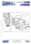
1
EDUS391100-F13 BSV-P Centralized Branch Selector units BSV4Q36PVJU BSV6Q36PVJU AMERICAS EDUS391100-F13 BSV-P Centralized Branch Selector units 1. 2. 3. 4. 5. 6. 7. Specifications ..............................................................................................2 Dimensions .................................................................................................3 Piping Diagrams..........................................................................................5 Wiring Diagrams..........................................................................................7 Electric Characteristics................................................................................9 Safety Devices Setting ..............................................................................10 Sound Levels ............................................................................................11 7.1 Overall ........................................................................................................ 11 7.2 Octave Band Level ..................................................................................... 11 8. Center of Gravity .......................................................................................12 9. Installation Manual ....................................................................................13 10.Accessories...............................................................................................30 10.1 Optional Accessories (For Unit) ................................................................. 30 BSV-P 1 Specifications EDUS391100-F13 1. Specifications Centralized Branch Selector units Model Power supply BSV4Q36PVJU BSV6Q36PVJU 1 phase, 208/230V, 60Hz 1 phase, 208/230V, 60Hz Number of branches 4 6 Capacity index of connectable indoor units per branch Max. 36 Max. 36 Number of connectable indoor units per branch Max. 5 Max. 5 Galvanized steel plate Galvanized steel plate Casing Dimensions: (H×W×D) in.(mm) Sound absorbing thermal insulation material Indoor unit Piping connection Liquid pipes in.(mm) 8-1/4 × 62-1/8 × 25 (210 x 1578 x 635) Foamed polyurethane. Frame resistant needle felt. 3/8 (9.5) C1220T (Brazing connection) 1 3/8 (9.5) C1220T (Brazing connection) 1 Gas pipes in.(mm) 5/8 (15.8) C1220T (Brazing connection) 1 5/8 (15.8) C1220T (Brazing connection) 1 Liquid pipes in.(mm) 1/2 (12.7) C1220T (Brazing connection) 2 3 5/8 (15.8) C1220T (Brazing connection) 2 3 in.(mm) 1-1/8 (28.6) C1220T (Brazing connection) 2 3 1-1/8 (28.6) C1220T (Brazing connection) 2 3 in.(mm) 3/4 (19.1) C1220T (Brazing connection) 2 3 1-1/8 (28.6) C1220T (Brazing connection) 2 3 Outdoor Suction unit gas pipes HP/LP gas pipes Mass (Weight) 8-1/4 × 41-1/2 × 25 (210 x 1054 x 635) Foamed polyurethane. Frame resistant needle felt. kg 60 89 Lbs 132 196 Installation manual. Attached pipe. Insulation tube. Clamps. Vinyl tube. Conduit mounting plate. Standard accessories Drawing No. Installation manual. Attached pipe. Insulation tube. Clamps. Vinyl tube. Conduit mounting plate. C: 4D072208A C: 4D072209A Notes: 1 In case of connecting with a 07~18 type indoor unit, match to the size of field pipe using the attached pipe. (Connection between the attached pipe and the field pipe must be brazed.) 2 In case of connection diameter does not suit on the triple piping side, need reducer (field supply). 3 Insulation is necessary (field supply) for the triple piping side. NOTE • A maximum of one closing kit per Branch Selector is allowed. • A maximum of two closing kits per outdoor unit system are allowed. • Do not use this closed pipe kit for the branch that is the furthest from the three-pipe side of the centralized Branch Selector unit. See following diagram: Top of centralized Branch Selector unit (BSV4036PVJU) UNIT D UNIT C UNIT B UNIT A Top of centralized Branch Selector unit (BSV6036PVJU) UNIT F UNIT E UNIT D UNIT C *Do not use the closed pipe kit UNIT B UNIT A *Do not use the closed pipe kit Connectable outdoor unit series REYQ-P, RWEYQ-P (Refer to the engineering data of the outdoor unit about details of the outdoor unit.) 1. 2. 3. 4. 5. Regulations & restrictions Unit cannot be placed one upon the other since top cover must be free from open/close for servicing. Piping parts such as EV cannot be replaced since foam insulated. Piping length between the centralized Branch Selector unit and indoor unit shall be max. 131 ft. The control box cannot be installed on any other location. 2 inspection hatches (17-3/4 in. / 451 mm) (BSV6Q36PVJU) or 1 inspection hatch (17-3/4 in. / 451 mm) (BSV4Q36PVJU) are required on each of the box for servicing in order to secure maintenance workability. 6. Need a different opening for unit replacement (to unload product) or indoor unit side piping maintenance. 7. Installation location must be where operating sound (refrigerant noise) shall not influence the environment. 8. If there is an extra branch (where the indoor unit is not connected), the optional closed pipe kit (KHFP26A100C) is required. 2 BSV-P EDUS391100-F13 Dimensions 2. Dimensions Unit (in.) 3D072212A BSV4Q36PVJU BSV-P 3 Dimensions Unit (in.) 3D072213A BSV6Q36PVJU EDUS391100-F13 4 BSV-P EDUS391100-F13 Piping Diagrams 3. Piping Diagrams BSV4Q36PVJU 3D064148A BSV-P 5 Piping Diagrams EDUS391100-F13 3D064149A BSV6Q36PVJU 6 BSV-P EDUS391100-F13 Wiring Diagrams 4. Wiring Diagrams PROTECTIVE GROUND 3D072210A BSV4Q36PVJU BSV-P 7 Wiring Diagrams EDUS391100-F13 PROTECTIVE GROUND 3D072211A BSV6Q36PVJU 8 BSV-P EDUS391100-F13 Electric Characteristics 5. Electric Characteristics MCA / MOP 4D072214 BSV-P 9 Safety Devices Setting EDUS391100-F13 6. Safety Devices Setting Model BSV4Q36PVJU BSV6Q36PVJU PC board fuse 250V 3.15A 250V 3.15A 4D072221 10 BSV-P EDUS391100-F13 Sound Levels 7. Sound Levels 7.1 Overall Location of microphone Notes: 1. Operating sound differs with operating and ambient conditions. 2. In case of other unit operating in the same system, operating sound will be generated, ever if indoor unit connected to Branch Selector unit is stopped. 3. These sound levels are based on JIS standard and sound data are reference. dB(A) Model 7.2 208/230V, 60Hz Operating Sound Stoppage Sound BSV4Q36PVJU 48 38 BSV6Q36PVJU 50 40 Octave Band Level 208/230V, 60Hz BSV4Q36PVJU (Reference) BSV6Q36PVJU (Reference) 4D072225 BSV-P 4D072226 11 Center of Gravity EDUS391100-F13 8. Center of Gravity BSV4Q36PVJU Unit (in.) 4D072215 BSV6Q36PVJU Unit (in.) 4D072216 12 BSV-P EDUS391100-F13 Installation Manual 9. Installation Manual INSTALLATION MANUAL III SYSTEM HEAT PUMP MODELS 〈Centralized BRANCHSELECTOR unit〉 BSV4Q36PVJU BSV6Q36PVJU English Français READ THESE INSTRUCTIONS CAREFULLY BEFORE INSTALLATION. KEEP THIS MANUAL IN A HANDY PLACE FOR FUTURE REFERENCE. LIRE SOIGNEUSEMENT CES INSTRUCTIONS AVANT L’INSTALLATION. CONSERVER CE MANUEL A PORTEE DE MAIN POUR REFERENCE ULTERIEURE. Espaçol LEA CUIDADOSAMENTE ESTAS INSTRUCCIONES ANTES DE INSTALAR. GUARDE ESTE MANUAL EN UN LUGAR A MANO PARA LEER EN CASO DE TENER ALGUNA DUDA. BSV-P 13 Installation Manual EDUS391100-F13 3P194121-5P 3P194121-5P 14 BSV-P EDUS391100-F13 Installation Manual BSV4Q36PVJU BSV6Q36PVJU VRVIII SYSTEM HEAT PUMP Installation manual CONTENTS 1. 2. 3. 4. 5. 6. 7. 8. 9. SAFETY CONSIDERATIONS .........................................................................................1 BEFORE INSTALLATION ................................................................................................4 SELECTING INSTALLATION SITE .................................................................................6 PREPARATIONS BEFORE INSTALLATION....................................................................6 CENTRALIZED B2!.#(S%,%#4/2 UNIT INSTALLATION .......................................7 REFRIGERANT PIPING WORK .....................................................................................8 ELECTRIC WIRING WORK ..........................................................................................12 INITIAL SETTING..........................................................................................................16 CHECK OPERATION AND TEST RUN .........................................................................17 1. SAFETY CONSIDERATIONS Read these “SAFETY CONSIDERATIONS” carefully before installing heat pump equipment. After completing the installation, make sure that the unit operates properly during a test run. Instruct customers on how to operate and maintain the unit. Inform customers that they should store this Installation Manual for future reference. Always ask a licensed installer or contractor to install this product. Improper installation can result in water or refrigerant leakage, electric shock, fire or explosion. Meanings of DANGER, WARNING, CAUTION, and NOTE Symbols: DANGER ...........Indicates an imminently hazardous situation which, if not avoided, will result in death or serious injury. WARNING .........Indicates a potentially hazardous situation which, if not avoided, could result in death or serious injury. CAUTION ..........Indicates a potentially hazardous situation which, if not avoided, may result in minor or moderate injury. It may also be used to alert against unsafe practices. NOTE .................Indicates situations that may result in equipment or property-damage accidents only. DANGER • Refrigerant gas is heavier than air and replaces oxygen. A massive leak can lead to oxygen depletion, especially in basements, and an asphyxiation hazard could occur leading to serious injury or death. • Do not ground units to water pipes, gas pipes, telephone wires or lightning rods as incomplete grounding can cause a severe shock hazard resulting in severe injury or death. Additionally, grounding to gas pipes could cause a gas leak and potential explosion causing severe injury or death. • If refrigerant gas leaks during installation, ventilate the area immediately. Refrigerant gas may produce toxic gas if it comes in contact with fire. Exposure to this gas could cause severe injury or death. English 1 3P194121-5P BSV-P 15 Installation Manual EDUS391100-F13 • After completing the installation work, check that the refrigerant gas does not leak throughout the system. • Do not install units in an area where flammable materials are present due to risk of explosions that can cause serious injury or death. • Safely dispose all packing and transportation materials in accordance with federal/state/local laws or ordinances. Packing materials such as nails and other metal or wood parts, including plastic packing materials used for transportation may cause injury or death by suffocation. WARNING • Only qualified personnel must carry out the installation work. Installation must be done in accordance with this installation manual. Improper installation may result in water leakage, electric shock or fire. • When installing the unit in a small room, take measures to keep the refrigerant concentration from exceeding allowable safety limits. Excessive refrigerant leaks, in the event of an accident in a closed ambient space, can lead to oxygen deficiency. • Use only specified accessories and parts for installation work. Failure to use specified parts may result in water leakage, electric shock, fire or the unit falling. • Install the heat pump on a foundation strong enough that can withstand the weight of the unit. A foundation of insufficient strength may result in the unit falling and causing injury. • Take into account strong winds, typhoons or earthquakes when installing. Improper installation may result in the unit falling and causing accidents. • Make sure that a separate power supply circuit is provided for this unit and that all electrical work is carried out by qualified personnel according to local, state, and national regulations. An insufficient power supply capacity or improper electrical construction may lead to electric shock or fire. • Make sure that all wiring is secured, that specified wires are used, and that no external forces act on the terminal connections or wires. Improper connections or installation may result in fire. • When wiring, position the wires so that the control box cover can be securely fastened. Improper positioning of the control box cover may result in electric shock, fire or the terminals overheating. • Before touching electrical parts, turn off the unit. • Be sure to install a ground fault circuit interrupter if one is not already available. This helps prevent electric shock or fire. • Securely fasten the outdoor unit terminal cover (panel). If the terminal cover/panel is not installed properly, dust or water may enter the outdoor unit causing fire or electric shock. • When installing or relocating the system, keep the refrigerant circuit free from substances other than the specified refrigerant (R410A) such as air. Any presence of air or other foreign substance in the refrigerant circuit can cause an abnormal pressure rise or rupture, resulting in injury. • Do not change the setting of the protection devices. If the pressure switch, thermal switch or other protection device is shorted and operated forcibly or parts other than those specified by Daikin are used, fire or explosion may occur. CAUTION • Do not touch the switch with wet fingers. Touching a switch with wet fingers can cause electric shock. • Do not allow children to play on or around the unit to prevent injury. • Do not touch the refrigerant pipes during and immediately after operation as the refrigerant pipes may be hot or cold, depending on the condition of the refrigerant flowing through the refrigerant piping, compressor, and other refrigerant cycle parts. Your hands may suffer burns or frostbite if you touch the refrigerant pipes. To avoid injury, give the pipes time to return to normal temperature or, if you must touch them, be sure to wear proper gloves. • Heat exchanger fins are sharp enough to cut. To avoid injury wear glove or cover the fins when working around them. • Install drain piping to proper drainage. Improper drain piping may result in water leakage and property damage. • Insulate piping to prevent condensation. 2 English 3P194121-5P 16 BSV-P EDUS391100-F13 Installation Manual • Be careful when transporting the product. • Do not turn off the power immediately after stopping operation. Always wait for at least 5 minutes before turning off the power. Otherwise, water leakage may occur. • Do not use a charging cylinder. Using a charging cylinder may cause the refrigerant to deteriorate. • Refrigerant R410A in the system must be kept clean, dry, and tight. (a) Clean and Dry -- Foreign materials (including mineral oils such as SUNISO oil or moisture) should be prevented from getting into the system. (b) Tight -- R410A does not contain any chlorine, does not destroy the ozone layer, and does not reduce the earth’s protection again harmful ultraviolet radiation. R410A can contribute to the greenhouse effect if it is released. Therefore take proper measures to check for the tightness of the refrigerant piping installation. Read the chapter Refrigerant Piping and follow the procedures. • Carefully read the chapter “REFRIGERANT PIPING WORK” and strictly observe the correct procedures. • Disposal requirements • Dismantling of the unit, treatment of the refrigerant, of oil and of other parts must be done in accordance with relevant local and national legislation. • Since R410A is a blend, the required additional refrigerant must be charged in its liquid state. If the refrigerant is charged in a state of gas, its composition can change and the system will not work properly. • The indoor unit is for R410A. See the catalog for indoor models that can be connected. Normal operation is not possible when connected to other units. • Remote controller (wireless kit) transmitting distance can be shorter than expected in rooms with electronic fluorescent lamps (inverter or rapid start types). Install the indoor unit far away from fluorescent lamps as much as possible. • Indoor units are for indoor installation only. Outdoor units can be installed either outdoors or indoors. • Do not install the heat pump in the following locations: (a) Where a mineral oil mist or oil spray or vapor is produced, for example, in a kitchen. Plastic parts may deteriorate and fall off or result in water leakage. (b) Where corrosive gas, such as sulfurous acid gas, is produced. Corroding copper pipes or soldered parts may result in refrigerant leakage. (c) Near machinery emitting electromagnetic waves. Electromagnetic waves may disturb the operation of the control system and cause the unit to malfunction. (d) Where flammable gas may leak, where there is carbon fiber or ignitable dust suspension in the air or where volatile flammables such as thinner or gasoline are handled. Operating the unit in such conditions can cause a fire. • Take adequate measures to prevent the outdoor unit from being used as a shelter by small animals. Small animals making contact with electrical parts can cause malfunctions, smoke or fire. Instruct the customer to keep the area around the unit clean. NOTE • Install the power supply and control wires for the indoor and outdoor units at least 3.5 feet away from televisions or radios to prevent image interference or noise. Depending on the radio waves, a distance of 3.5 feet may not be sufficient to eliminate the noise. • Dismantling the unit, treatment of the refrigerant, oil and additional parts must be done in accordance with the relevant local, state, and national regulations. • Do not use the following tools that are used with conventional refrigerants: gauge manifold, charge hose, gas leak detector, reverse flow check valve, refrigerant charge base, vacuum gauge or refrigerant recovery equipment. • If the conventional refrigerant and refrigerator oil are mixed in R410A, the refrigerant may deteriorate. • This heat pump is an appliance that should not be accessible to the general public. • The wall thickness of field-installed pipes should be selected in accordance with the relevant local, state, and national regulations. English 3 3P194121-5P BSV-P 17 Installation Manual EDUS391100-F13 2. BEFORE INSTALLATION 2-1 CAUTION CONCERNING NEW REFRIGERANT SERIES • Since R410A is a mixed refrigerant, the required additional refrigerant must be charged in its liquid state. (If the system is charged with refrigerant in its gaseous state, due to composition change, the system will not function normally.) The indoor/outdoor unit is designed for R410A use. See the catalogue for indoor/outdoor unit models that can be connected. (Normal operation is not possible when connecting units that are originally designed for other refrigerants.) 2-2 PRECAUTIONS • Hold the unit by the Hanging brackets (4 points) when opening the box and moving it, and do not lift it holding on to any other part especially the refrigerant pipe. • About installation of outdoor and indoor unit, refer to the installation manual provided with the outdoor and the indoor unit. • This unit, both indoor and outdoor, is suitable for installation in a commercial and light industrial environment. If installed as a household appliance it could cause electromagnetic interference. 2-3 ACCESSORIES Check the following Accessories are included with your unit. NOTE • Do not throw away any of the Accessories until installation is complete. 〈BSV4Q36PVJU〉 Name Quantity 1) Accessory pipes 4 pcs. 1)-1 4 pcs. 1)-2 2) Clamp 13 pcs. 3) Insulation tube 16 pcs. 2)-1 2)-2 4 pcs. 3)-1 4 pcs. 3)-2 Vinyl tube 1 pc. Conduit mounting plate 1 pc. 1 pc. Explanation Document 1 copy Installation manual Shape φ3/8 in. φ5/8 in. (Small) (Large) (Small) (Large) 〈BSV6Q36PVJU〉 Name Quantity 1) Accessory pipes 6 pcs. 1)-1 6 pcs. 1)-2 2) Clamp 17 pcs. 2)-1 3) Insulation tube 24 pcs. 2)-2 6 pcs. 3)-1 6 pcs. 3)-2 Vinyl tube 1 pc. Conduit mounting plate 1 pc. 1 pc. Explanation Document 1 copy Installation manual Shape φ3/8 in. φ5/8 in. (Small) (Large) (Small) (Large) * • A reducing joint (field supply) will be required if the on-site pipe diameter specified in the installation manual for the outdoor unit or in the relevant engineering data book differs from the pipe diameter on the outdoor unit side of the centralized BRANCHSELECTOR unit. * • The installation material on the outdoor unit side is a field supply. 4 English 3P194121-5P 18 BSV-P EDUS391100-F13 Installation Manual 2-4 COMBINATION 4HISCENTRALIZED BRANCHSELECTOR unit is only for systems for Models REYQ-P and RWEYQ-P. It cannot be connected to systems for Models REYQ-M. For series of applicable indoor units, refer to the catalog or other literature. Select the centralized BRANCHSELECTOR unit to fit the total capacity (sum of unit’s capacity) and max. number OFTHEindoor units to be connected downstream, refer to the Table 1. About indoor unit’s capacity, refer to the Table 2. Table 1 Model BSV4Q36PVJU BSV6Q36PVJU Total capacity of all downstream indoor units A ≤ 144 (*) A ≤ 216 (*) Max. number of all downstream indoor units 20 (*) 30 (*) * The total capacity of indoor units connectable to each branch connector is up to 36 and the total number of indoor units connectable to each branch connector is up to 5 units respectively. Table 2 Capacity expressed as indoor unit’s model No. Indoor unit’s capacity (for use in computation) 07 7.5 09 9.5 12 12 18 18 24 24 30 30 36 36 <Example> In case of the centralized BRANCHSELECTOR unit witch connect a FXMQ09P and a FXFQ18P. Total capacity = 9.5+18 = 27.5 2-5 CHECK ITEM • For the following items, take special care during construction and check after installation is finished. Completion check items Check items Problems Check Are the centralized BRANCHSELECTOR units installed securely?&alling, vibration, and operating noise Have you performed a gas leak test? Does not cool or heat Is the insulation complete? (Refrigerant pipe and pipe connection part) Water leaking Is the voltage the same as that listed on the unit’s nameplate? Does not operate/burnt out Are all the wiring and piping correct? Does not operate/burnt out Is the unit grounded? Dangers during electrical leak Is the thickness of the power cord as specified? Does not operate/burnt out Hand-over check items Check items Check Did you close the control box cover? Did you hand the operating manual and warranty card to the customer? Are the transmission wiring and piping lines of each unit not connected in reverse? English 5 3P194121-5P BSV-P 19 Installation Manual EDUS391100-F13 3. SELECTING INSTALLATION SITE Select an installation site where the following conditions are satisfied and that meets with your customer’s approval. Where is resistible against weight of centralized BRANCH3ELECTOR unit. Locations where the wall is not significantly tilted. Where sufficient clearance for maintenance and service can be ensured. (Refer to Fig. 1, Fig. 2) Locations where an inspection hatch (Refer to Fig. 1) can be installed to control box side (*1). Where the total pipe length involving indoor unit and outdoor unit is below the allowable pipe length. (See installation manual attached to outdoor unit.) Where the sound of passing refrigerant does not cause problems. Never install the centralized BRANCH 3ELECTORUNITONthe opposite side of the ceiling of the living room. (unit: inch) Top of centralized BS unit 12 or more 12 or more Top of centralized BS unit 12 or more 17-3/4(*1) In the case of BSV4Q36PVJU Indoor unit side (two pipes) Inspection hatch 17-3/4(*1) In the case of BSV6Q36PVJU 2 or more Inspection hatch (24)(*3) (24)(*3) 10 or more 12 or more (unit: inch) Fig. 1 (*2) Fig. 2 (*1) Be sure to install the inspection hatch on the control box side. Another opening is required in the case of taking down the product. (*2) Secure the service space for the local piping. (*3) The space is required to locate the top plate of the centralized BRANCHSELECTOR unit at the time of servicing. NOTES • Study if the installation location is strong enough to hold the weight of the unit, and if necessary reinforce the area with a beam or other member and then install suspension bolts. Use the suspension bolts to install the unit. (Refer to “4. PREPARATIONS BEFORE INSTALLATION”) sInstall the centralized BRANCHSELECTOR unit and its power and transmission wirings at least 3.5 feet away from tele sions and radios to prevent picture interference and noise. (Depending on the incoming signal strength, a distance of 3.5 feet may not be sufficient to eliminate noise.) 4. PREPARATIONS BEFORE INSTALLATION Refer the Fig. 3 and install the suspension bolts and hanging brackets. 〈Suspension bolts: For supporting the product〉 • Use 5/16 or 3/8 UNC suspension bolts. • When holes are to be made anew, used embedded inserts and embedded foundation bolts. When holes are already provided, use hole-in-anchors or the like. Install the centralized BRANCHSELECTOR unit so that its weight can be withstood. 〈Hanging bracket: For supporting the connection pipe〉 • Be sure to support the connection pipe around the unit using hanging brackets that are kept within 40 inch of the body side surface. Hanging excessive weight on the centralized BRANCHSELECTOR unit hanging bracket could cause the unit to fall and injure someone. 6 English 3P194121-5P 20 BSV-P EDUS391100-F13 Installation Manual A (unit: 19-1/2 centralized BS unit BSV4Q36PVJU BSV6Q36PVJU A 43-3/8 64-1/8 <Suspension bolt pitch> Slab Hanging bracket Unit proper 40 or less Anchor Long nut or turnbuckle Suspension bolt 40 or less Note: All the above parts are part to be procured in the field. <Example installation> Fig. 3 CENTRALIZED B2!.#(3%,%#4/2 UNIT INSTALLATION Use only accessories and parts which are of the designated specification when installing. (1) Attach the hooks to the suspension bolts. Be sure to use the nuts (5/16 or 3/8 UNC: 3 pcs, 4 locations) and washers (For 5/16 UNC: Outside diameter dimension 15/16 to 1-1/8 inch, For 3/8 UNC: Outside diameter 1-3/16 to 1-3/8 inch: 2 pcs, 4 locations) (field supply) from both the top and bottom sides of the hanging bracket and make sure they are tightened correctly. Washer (Field supply) Nut (Field supply) Hanging bracket 3/8~5/8 inch Nut (Double nut) (Field supply) Centralized BRANCH 3ELECTORUNITPROPER NOTES 4HECentralized BRANCHSELECTOR unit has a top and a bottom, so doNOT Suspension bolt (Field supply) INSTALLITupside down. The diagonal lines in the Fig. 4 is the top side. (Failing to do so may prevent the unit from operating properly and increase the volume of the operating noise.) Fig. 4 English 7 3P194121-5P BSV-P 21 Installation Manual 6 EDUS391100-F13 REFRIGERANT PIPING WORK &ORINSTRUCTION for installing pipe between the outdoor unit and centralized BRANCHSELECTOR unit, selecting a refrige branch kit, and installing pipe between the refrigerant branch kit and the indoor unit, refer to the installation manual and equipment design materials included with the outdoor unit. • Before beginning the work, always check to make sure the type of refrigerant used is R410A. (The unit will not operate correctly with a different type of refrigerant.) • Insulate all of the pipe including the liquid pipes, HP/LP gas pipe, suction gas pipe, gas pipes, and the pipe connections for these. Not insulting these pipes could result in water leaks or burns. In particular, suction gas flows in the HP/LP gas pipe during full cooling operation, so the same amount of insulation as used for the suction gas pipe is required. In addition, high-pressure gas flows in the HP/LP gas pipe and gas pipes, so use insulation that can withstand more than 250°F. • Reinforce the insulation material when necessary for the installation environment. Refer to the following as a guideline. • For 86°F, RH75% to 80%: Thickness at least 5/8 inch • For 86°F, over RH80%: Thickness at least 3/4 inch If not reinforced, condensation could form on the surface of the insulation. For details, refer to the Engineering data book. NOTES • This product only uses the new refrigerant (R410A). Be sure to use the special pipe cutters for R410A, during installation. • Make sure that nothing besides the specified refrigerant, such as air, gets into the refrigerant pipe. • If refrigerant gas leaks during the work, ventilate the area. (The outdoor units are filled with refrigerant.) 6-1 PIPING MATERIAL SELECTION • Use only pipes which are clean inside and outside and which do not accumulate harmful sulfur, oxidants, dirt, cutting oils, moisture or other contamination. (Foreign materials inside pipes including oils for fabrication must be 0.14 grain/10 feet or less.) • Use the following items for the refrigerant piping. Material: Jointless phosphor-deoxidized copper pipe Size: See “Example of connection” to determine the correct size. Thickness: Select a thickness for the refrigerant pipe which complies with national and local laws. For R410A, the design pressure is 478 psig. • For information regarding the piping allowable maximum length, allowable height difference, and allowable length after a branch, refer to the installation manual that came with the outdoor unit or engineering data book. • The refrigerant branch kit (sold separately) is required for piping branches. For information on how to select a refrigerant branch kit, refer to the installation manual that came with the outdoor unit or engineering data book. 6-2 PROTECTION AGAINST CONTAMINATION WHEN INSTALLING PIPES Protect the pipe to prevent moisture, dirt, dust, etc. from entering the pipe. Place Outdoor Indoor Installation period More than a month Less than a month Regardless of the period Protection method Pinch the pipe Pinch or tape the pipe NOTE Exercise special caution to prevent dirt or dust when passing pipe through holes in walls and when passing pipe edges to the exterior. 8 English 3P194121-5P 22 BSV-P EDUS391100-F13 Installation Manual 6-3 PIPING CONNECTION WORK PRECAUTIONS • When brazing refrigerant pipe, begin working after replacing the nitrogen (*1) or perform brazing while nitrogen is flowing in the refrigerant pipe (*2) (Refer to Fig. 5), and at the end made the indoor unit and centralized BRANCHSELECTOR unit flare connection. (*1) For details on nitrogen replacement, see the “VRV installation manual” (available at any Daikin dealer). (*2) The pressure regulator for the nitrogen released when doing the brazing should be set to about 2.9 psig (Enough to feel a slight breeze on your cheek). Pressure-reducing valve Part to be brazed Taping Nitrogen Nitrogen Valve Refrigerant pipe Fig. 5 NOTES • Do not use an anti-oxidizing agent when brazing the pipe. Residual debris could clog the pipe or cause parts to malfunction. • Do not use a flux when brazing the refrigerant pipe joints. Using a chlorine flux may cause the pipes to corrode, and if it contains fluoride it may cause the refrigerant lubricant to deteriorate, adversely affecting the refrigerant pipe system. Use phosphor copper brazing (B-Cu93P-710/795: ISO 3677) which does not require flux. 6-4 PIPE SIZE SELECTION From Example of connection 1 and 2 below and Table 3, 4, select the pipe size between the outdoor unit (refrigerant branch kit) and centralized Branch Selector unit, and between the centralized Branch Selector unit and the indoor unit (refrigerant branch kit). The closed pipe kit (KHFP26A100C) should be used for selecting reluctantly 6-branch type (BSV6Q36PVJU) as 5-branches and 4-branch type (BSV4Q36PVJU) as 3 branches, and it is connected to the branch not connected for the indoor unit. Example of connection 1: When 1 indoor unit is connected downstream from the centralized BRANCH Select from Table 4 depending on the capacity type of the indoor unit. <Upstream> <Downstream> Suction gas pipe Centralized BS unit Liquid pipe English *2 HP/LP gas pipe Gas pipe To refrigerant branch kit or outdoor unit Determine using Table 3 based on the total capacity of the indoor units connected downstream. *1 Liquid pipe 3ELECTOR unit Indoor unit <Downstream> 9 3P194121-5P BSV-P 23 Installation Manual EDUS391100-F13 Example of connection 2: When there is a branch downstream from the centralized BRANCHSELECTOR unit Determine using Table 3 based on the total capacity of the indoor units connected downstream. *1 (inch) Use the following pipes: Gas pipe: F5/8 Liquid pipe: F3/8 <Upstream> Suction gas pipe Refrigerant branch kit <Downstream> Centralized Branch Selector unit *2 HP/LP gas pipe Liquid pipe Liquid pipe Gas pipe To refrigerant branch kit or outdoor unit Refer to the installation manual and engineering data book included with the outdoor it to decide on the respective sizes of pipes connecting to the refrigerant branch kits and those connecting between the refrigerant branch kits and indoor units. Indoor unit Indoor unit Indoor unit Table 3 Indoor unit total capacity and pipe size (inch) Indoor capacity index (Q) Q < 54 54 ≤ Q < 72 72 ≤ Q < 111 111 ≤ Q < 162 162 ≤ Q ≤ 216 Pipe size (outer diameter) Suction gas pipe HP/LP gas pipe φ5/8 φ1/2 φ3/4 φ5/8 φ7/8 φ3/4 φ1-1/8 φ1-1/8 Liquid pipe φ3/8 φ1/2 φ5/8 *1 In the case of connection to the main pipe, refer to the installation manual provided to the outdoor unit or the engineering data book. Table 4 Indoor unit connection pipe size (inch) Capacity type of indoor units 7.5, 9.5, 12, 18 24, 30, 36 Pipe size (outer diameter) Gas pipe φ1/2 φ5/8 Liquid pipe φ1/4 φ3/8 *2 The centralized Branch Selector unit downstream connection pipe sizes are shown below. If the pipe diameter differs from that of the indoor unit connection pipe size selected from Table 4, follow the instructions in “6-5 PIPING CONNECTION” and use the included pipe to make the connection. 4ABLE#ENTRALIZED"RANCH3ELECTORUNITCONNECTIONPIPESIZE (inch) Centralized BS unit BSV4Q36PVJU BSV6Q36PVJU 10 Pipe size (outer diameter) Gas pipe Liquid pipe φ5/8 φ3/8 English 3P194121-5P 24 BSV-P EDUS391100-F13 Installation Manual 6-5 PIPING CONNECTION Follow the connection example below and connect the site pipe. When the downstream indoor unit total capacity is 36 or less and when one indoor unit with a capacity of 24 to 36 is connected downstream. Suction gas pipe (Site pipe) Centralized BS unit (Top) HP/LP gas pipe (Site pipe) Liquid pipe (Site pipe) Unit D Unit C Unit B Unit A Gas pipe (Site pipe) Liquid pipe (Site pipe) NOTE: SEE GRAPHIC ON PAGE 2 OR PAGE 30 FOR CLOSED PIPE KIT LIMITATIONS. When one indoor unit with a capacity of 7.5 to 18 is connected downstream Suction gas pipe (Site pipe) Centralized BS unit (Top) HP/LP gas pipe (Site pipe) Liquid pipe (Site pipe) Unit D Unit C Unit B Unit A Accessory pipes 1)-2 NOTE: This graphic should only be used as an example. Gas pipe (Site pipe) NOTE: SEE GRAPHIC ON PAGE 2 OR PAGE 30 FOR CLOSED PIPE KIT LIMITATIONS. Accessory pipes 1)-1 Liquid pipe (Site pipe) 6-6 PIPE INSULATION • After the gas leak inspection is completed, refer to the following figures and use the insulation tube 3) (Accessory) and clamps 2) (Accessory) to apply the insulation. NOTES • Insulate all of the pipe including the liquid pipes, HP/LP gas pipe, suction gas pipe, gas pipe, and the pipe connections for these. Not insulting these pipes could result in water leaks or burns. In particular, suction gas flows in the HP/LP gas pipe during full cooling operation, so the same amount of insulation as used for the suction gas pipe is required. In addition, high-pressure gas flows in the HP/LP gas pipe and gas pipes, so use insulation that can withstand more than 250°F. • When reinforcing the insulation material for the installation environment, also reinforce the insulation on the pipe protruding from the unit and on the pipe connections. Locally purchase the insulation required for the reinforcement work. Insulation tube (Field supply) Suction gas pipe (Note 1) HP/LP gas pipe (Note 1) Clamp (Field supply) Centralized Branch Selector unit Liquid pipe Insulation tube (Field supply) Clamp 2)-2 (Accessory) Insulation tube 3)-1 (Accessory) Clamp (Field supply) English Clamp 2)-2 (Accessory) Insulation tube 3)-2 (Accessory) Gas pipe (Note 1) Liquid pipe 11 3P194121-5P BSV-P 25 Installation Manual EDUS391100-F13 Insulation Attachment Instructions Three-pipes distribution side: Refrigerant branch kit or outdoor unit connection side (1) Attach the insulation tube. (Field supply) Pipe insulation tube (Site pipe side) Insulation Attachment Instructions Two-pipes distribution side: Indoor unit connection side Reducer (Field supply) (1) Attach the insulation tube. (Accessory) Pipe connection (Field supply) Bind the insulation material with an appropriate material, such as a tape, so that there will be no clearance. Pipe insulation tube (Product pipe side) Centralized BS unit (3) Use the clamps (field supply) to hold both ends. Note 1: For suction gas pipe, HP/LP gas pipe, and gas pipes, after attaching the insulation tube, wrap more insulation (field supply) around the connections. Pipe insulation tube (Product pipe side) Pipe connection Pipe insulation tube (Site pipe side) Centralized BS unit (2) Seal (2) Seal (3) Use the clamps (Accessory) to hold both ends. Insulation material (Field supply) Insulation Installation Precautions 1. Seal so that air cannot be in and out of the end. 2. Do not over-tighten the clamp so as to maintain the insulation thickness. 3. Be sure to attach the insulation tube with the seam facing up. (See the right figure.) Seam Attach with facing up 7. ELECTRIC WIRING WORK 7-1 GENERAL INSTRUCTIONS • • • • • • All wiring must be performed by an authorized electrician. All field supplied parts and materials, electric works must conform to local codes. Always ground wires. (In accordance with national regulations of the pertinent country.) Always turn off the power before performing the electric wire installation work. Follow the “WIRING DIAGRAM” attached to the unit body to wire the outdoor unit and indoor units. Properly connect wire of the specified wire type and copper thickness. Also use the included clamp to avoid applying excessive force to the terminal (field wire, ground wire). • Do no let the ground wire should come in contact with gas pipes, water pipes, lighting rods or telephone ground wires. • Gas pipes: gas leaks can cause explosions and fire. • Water pipes: cannot be grounded if hard vinyl pipes are used. • Telephone ground and lightning rods: the ground potential when struck by lightning gets extremely high. • A ground fault circuit interrupter capable of shutting down the power supply to the entire system must be installed. This system consists of centralized Branch Selector units. Mark each Branch Selector unit as unit A, unit B . . . , f and make sure the terminal block label to the outdoor unit and indoor unit are properly matched. If wiring and pipin the outdoor unit, centralized Branch Selector unit and an indoor unit are mismatched, the system may cause a malfunction. • Do not turn on the power supply (branch switches, overload interrupters) until all other work is done. 12 English 3P194121-5P 26 BSV-P EDUS391100-F13 Installation Manual 7-2 EXAMPLE FOR THE WHOLE SYSTEM Power supply Outdoor unit Power supply wiring Main switch Power supply Transmission wiring Switch Fuse Main switch BSV4Q unit Indoor unit Remote controller BSV4Q unit Indoor unit Cooling-only indoor unit Remote controller Remote controller 7-3 POWER CIRCUIT, SAFETY DEVICE AND CABLE REQUIREMENTS • A power circuit (Refer to Table 6) must be provided for connection of the unit. This circuit must be protected with the required safety devices, i.e. a main switch, a slow blow fuse on each phase and a ground fault circuit interrupter. • When using residual current operated circuit breakers, be sure to use a high-speed type (0.1 second or less) 30mA rated residual operating current. • Use copper conductors only. • Use insulated wire for the power cord. • Select the power supply cable type and size in accordance with relevant local and national regulations. • Specifications for local wiring are in compliance with IEC60245. • Use wire type H05VV-U3G for power supply wiring. And the size must comply with local codes. • Use vinyl cord with sheath or cable (2 wire) of AWG18-16 for transmission wiring. Table 6 Model BSV4Q36P BSV6Q36P Type Hz Units Voltage Min. Max. VJ 60 208/230 187 253 MCA: Minimum Circuit Ampacity (A); Power supply MCA MOP 0.4 15 0.6 MOP: Maximum Overcurrent Protective Device (A) NOTES The above Table 6 of electrical characteristics refers to one centralized Branch Selector unit. • See the engineering data book for other details. English 13 3P194121-5P BSV-P 27 Installation Manual EDUS391100-F13 7-4 WIRING EXAMPLE • Here is shown a wiring example for one system transmission wiring. • Connect terminals F1 and F2 (TO IN/D UNIT) on the control PC BOARD in the outdoor unit control box and terminals F1 and F2 (TO OUT/D UNIT) of the control PC BOARD (A1P) of the first Branch Selector unit A. COOL/HEAT selector wiring Transmission wiring Absolutely do not connect the power supply wiring. Use 2-core wires. (There is no polarity.) IN / OUT OUT / OUT F1 F2 F1 F2 C/H SELECTOR C B A PC BOARD PC BOARD PC BOARD INDOOR INDOOR INDOOR INDOOR C/H SELECTOR UNIT B C/H SELECTOR UNIT C C/H SELECTOR UNIT D UNIT A C B A C B A C B A F1 F2 F1 F2 F1 F2 F1 F2 F1 F2 F1 F2 F1 F2 Indoor unit Indoor unit Indoor unit COOL/HEAT selector COOL/HEAT selector COOL/HEAT selector F1 F2 OUTDOOR BS UNIT UNIT F1 F2 F1 F2 F1 F2 Indoor unit COOL/HEAT selector TO IN/D UNIT TO OUT/D UNIT F1 F2 F1 F2 F1 F2 Final BS unit A TO IN/D UNIT TO OUT/D UNIT F1 F2 F1 F2 B C F1 F2 Indoor unit Indoor unit COOL/HEAT COOL/HEAT selector selector C/H SELECTOR BS unit B Centralized BS unit A PC BOARD Cooling-only indoor unit Outdoor unit C/H SELECTOR Use 3-core wires. (There is polarity. Match the terminal numbers.) A B C F1 F2 F1 F2 Cooling/Heating selectable indoor unit NOTES 1. Connect a cooling-only indoor unit to terminals F1 and F2 (TO OUT/D UNIT) of the final BS unit. 2. Use 2-core wire for the transmission wiring. Using a multi-core wire with 3 or more cores when two or more indoor units are used at once could cause abnormal stoppage. (Only use 3-core wire in the COOL/HEAT selector.) 3. Absolutely do not connect the power supply wiring to the transmission wiring terminal block. Doing so could damage the entire system. 4. For the transmission wiring, use wire that is within the following ranges. Exceeding these limits could cause a transmission error (1) Between an outdoor unit and centralized BS unit, Between a centralized BS unit and indoor unit, and Sub-branching Between a centralized BS unit and BS unit Maximum wiring length: 3280 ft. or less F1 F2 F1 F2 F1 F2 branch Total wiring length: 6560 ft. or less Branch point max: 16 branch points (2) Between a centralized BS unit and COOL/HEAT F1 F2 F1 F2 F1 F2 F1 F2 selector Maximum wiring length: 1640 ft. or less 7-5 WIRING CONNECTIONS Remove the control box cover on the side and follow the directions to connect the wires. 〈Transmission wiring〉 Remove the control box cover and connect the wires to F1 and F2 (TO IN/D UNIT: A~F) , F1 and F2 (centralized Branch Selector UNIT) and F1 and F2 (TO OUT/D UNIT) transmission wiring terminals (PC BOARD (A1P)). Indoor units E and F are BSV6Q model only. At this time, pass the wiring into the unit through the wiring through hole and use the clamps 2) (Accessory) to securely hold the wires (in 2 places). NOTE Check that the piping line coincides with the transmission wiring. 14 English 3P194121-5P 28 BSV-P EDUS391100-F13 Installation Manual 〈Power supply wiring and ground wire〉 Cup washer Remove the control box cover and connect the power supply wiring to the power terminal block (X1M). Ring-type crimp Also connect the ground wire to the ground wire terminal. Pass both the style terminal power supply wire and the ground wire together through the wire through hole with the conduit mounting plate (Accessory) and into the control box Cut out section and use the clamps 2) (Accessory) to securely hold the wires (in 1 place). Be sure to wire the ground wire so that comes out of the slit in the cup washer. (Not doing so could cause insufficient ground wiring and causing the wire not to function as a ground.) Power supply wire (to L1 and L2 terminals) Transmission wiring from indoor unit (to F1 and F2 terminals of indoor unit) (1-1/2in.) (1in.) Power supply and ground wire sheath Control box Terminal block Ground wire Clamp 2)-1 Vinyl tube (Accessory) (Accessory) Lock nut (Field supply) Clamp 2)-1 (Accessory) Conduit mounting plate (Accessory) Conduit (Field supply) Vinyl tube (Accessory) Clamp 2)-1 (Accessory) Ground terminal Power supply and ground wires Transmission wiring from BS unit (to F1 and F2 terminals of BS unit) Transmission wiring from outdoor unit (to F1 and F2 terminals of outdoor unit) Wire Wire fitting Clamp 2)-1 (Accessory) Transmission wiring from indoor unit (to F1 and F2 terminals of indoor unit) Liquid side pipe Clamp 2)-1 (Accessory) Transmission wiring to indoor unit (to F1 and F2 terminals on indoor side) Rear side NOTES Insulation sleeve • Use ring-type crimp style terminal for connections to Ring-type crimp Electric wire the power terminal block. (Refer to Fig. 6) style terminal Also, insulate the crimped area by attaching an insulation sleeve, etc. If these are not available, see the following section. Fig. 6 (a) Wiring of different thicknesses cannot be conDo not connect Do not connect Connect wires of the nected to the power terminal block. wires of different wires of the same same gauge to both gauges. gauge to one side. (A loose connection could cause abnormal heat- sides. ing.) (b) When connecting wire of the same diameter, make the connection as shown in the Fig. 7. • Do not finish the conductive part of the power supply Fig. 7 wires with lead-tin solder. • Use an appropriate screwdriver for tightening the Table 7 terminal screw. Terminal screw size Tightening torque (ft·lbf) Using a screwdriver that is too small could damage M3.5 (COOL/HEAT selector/transmission 059-0.71 wiring terminal block) the screw head and prevent proper tightening. M4 (Power supply terminal block) 0.87-1.06 • Over tightening the terminal screw could damage the M4 (Ground terminal) 1.12-1.37 screw. Refer to the Table 7 for the terminal screw tightening torque. English 15 3P194121-5P BSV-P 29 Accessories EDUS391100-F13 10. Accessories 10.1 Optional Accessories (For Unit) Model BSV4Q36PVJU Item Cool / Heat Selector BSV6Q36PVJU KRC19-26A6 Closed Pipe Kit KHFP26A100C 3D072224 NOTE • A maximum of one closing kit per Branch Selector is allowed. • A maximum of two closing kits per outdoor unit system are allowed. • Do not use this closed pipe kit for the branch that is the furthest from the three-pipe side of the centralized Branch Selector unit. See following diagram: Top of centralized Branch Selector unit (BSV4036PVJU) UNIT D UNIT C UNIT B UNIT A *Do not use the closed pipe kit 30 Top of centralized Branch Selector unit (BSV6036PVJU) UNIT F UNIT E UNIT D UNIT C UNIT B UNIT A *Do not use the closed pipe kit BSV-P Daikin Industries, Ltd.’s products are manufactured for export to numerous countries throughout the world. Daikin Industries, Ltd. does not have control over which products are exported to and used in a particular country. Prior to purchase, please therefore confirm with your local authorized importer, distributor and/or retailer whether this product conforms tot he applicable standards, and is suitable for use, in the region where the product will be used. This statement does not purport to exclude, restrict or modify the application of any local legislation. dddddfdf Ask a qualified installer or contractor to install this product. Do not try to install the product yourself. Improper installation can result in water or refrigerant leakage, electrical shock, fire, or explosion. Use only those parts and accessories supplied or specified by Daikin. Ask a qualified installer or contractor to install those parts and accessories. Use of unauthorized parts and accessories or improper installation of parts and accessories can result in water or refrigerant leakage, electrical shock, fire, or explosion. Read the User’s Manual carefully before using this product. The User’s Manual provides important safety instructions and warnings. Be sure to follow these instructions and warnings. If you have any inquiries, please contact your local importer, distributor, or retailer. © 2011 Daikin Industries, Limited. Daikin, Daikin AC Absolute Comfort and its design, VRV, REFNET, and Quaternity, Daikin Altherma are trademarks of Daikin Industries, Limited. ISO 9001 is a plant certification system defined by the International Organization for Standardization (ISO) relating to quality assurance. ISO 9001 certification covers quality assurance aspects related to the “design, development, manufacture, installation, and supplementary service” of products manufactured at the plant. ISO 14001 is the standard defined by the International Organization for Standardization (ISO) relating to environmental management systems. Our group has been acknowledged by an internationally accredited program of environmental protection procedures and activities to meet the requirements of ISO 14001. AMERICAS 1645 Wallace Drive, Suite 110 Carrollton, TX75006 [email protected] www.daikinac.com Specifications, designs and other content appearing in this brochure are current as of June 2011 but subject to change without notice. EDUS391100-F13 Printed in U.S.A. 6/2011 B AK