1
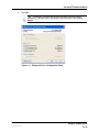
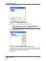
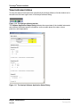
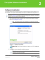
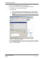
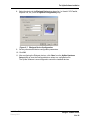
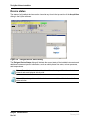
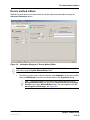
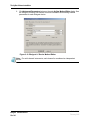
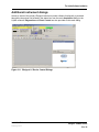
Eksigent® Software Drivers
Analyst® Software 1.5.1, 1.5.2, 1.6, TF 1.5.1
HyStar® 3.2
Xcalibur® 1.3, 1.4, 2.0, 2.1, 2.2
Installation Guide
D5031161 A
February 2012
This document is provided to customers who have purchased
AB Sciex equipment to use in the operation of such AB Sciex
equipment. This document is copyright protected and any reproduction
of this document or any part of this document is strictly prohibited,
except as AB Sciex may authorize in writing.
Software that may be described in this document is furnished under a
license agreement. It is against the law to copy, modify, or distribute
the software on any medium, except as specifically allowed in the
license agreement. Furthermore, the license agreement may prohibit
the software from being disassembled, reverse engineered, or
decompiled for any purpose.
Portions of this document may make reference to other manufacturers
and/or their products, which may contain parts whose names are
registered as trademarks and/or function as trademarks of their
respective owners. Any such use is intended only to designate those
manufacturers' products as supplied by AB Sciex for incorporation into
its equipment and does not imply any right and/or license to use or
permit others to use such manufacturers' and/or their product names
as trademarks.
AB Sciex makes no warranties or representations as to the fitness of
this equipment for any particular purpose and assumes no
responsibility or contingent liability, including indirect or consequential
damages, for any use to which the purchaser may put the equipment
described herein, or for any adverse circumstances arising therefrom.
For research use only. Not for use in diagnostic procedures.
The trademarks mentioned herein are the property of
AB Sciex Pte. Ltd. or their respective owners. Eksigent is a division of
AB Sciex, LLC.
AB SCIEX™ is being used under license.
Eksigent
5875 Arnold Road, Dublin, CA 94568.
AB Sciex LP is ISO 9001 registered.
© 2012 AB SCIEX.
Printed in Canada.
Contents
Chapter 1 The Analyst® Software Installation. . . . . . . . . . . . . . . . . . . . . . . . . . . . 5
Software Installation . . . . . . . . . . . . . . . . . . . . . . . . . . . . . . . . . . . . . . . . . . . . . . .5
Driver configuration . . . . . . . . . . . . . . . . . . . . . . . . . . . . . . . . . . . . . . . . . . . . . .6
Configure the LC system . . . . . . . . . . . . . . . . . . . . . . . . . . . . . . . . . . . . . . . . . .8
Create hardware profiles using the Analyst Software . . . . . . . . . . . . . . . . . . . .8
View instrument status . . . . . . . . . . . . . . . . . . . . . . . . . . . . . . . . . . . . . . . . . .12
Build acquisition methods . . . . . . . . . . . . . . . . . . . . . . . . . . . . . . . . . . . . . . . .13
Peak parking . . . . . . . . . . . . . . . . . . . . . . . . . . . . . . . . . . . . . . . . . . . . . . . . . .13
Chapter 2 The HyStar Software Installation . . . . . . . . . . . . . . . . . . . . . . . . . . . . 15
Software Installation . . . . . . . . . . . . . . . . . . . . . . . . . . . . . . . . . . . . . . . . . . . . . .15
Driver configuration . . . . . . . . . . . . . . . . . . . . . . . . . . . . . . . . . . . . . . . . . . . . .16
Configure the LC system . . . . . . . . . . . . . . . . . . . . . . . . . . . . . . . . . . . . . . . . .17
Mass Spectrometer Configuration using the HyStar Software . . . . . . . . . . . .17
Device status . . . . . . . . . . . . . . . . . . . . . . . . . . . . . . . . . . . . . . . . . . . . . . . . . .20
Device method editors . . . . . . . . . . . . . . . . . . . . . . . . . . . . . . . . . . . . . . . . . . .21
Additional instrument dialogs . . . . . . . . . . . . . . . . . . . . . . . . . . . . . . . . . . . . . .23
Data acquisition . . . . . . . . . . . . . . . . . . . . . . . . . . . . . . . . . . . . . . . . . . . . . . . .24
Chapter 3 The Xcalibur Software Installation . . . . . . . . . . . . . . . . . . . . . . . . . . . 25
Software Installation . . . . . . . . . . . . . . . . . . . . . . . . . . . . . . . . . . . . . . . . . . . . . .25
Driver configuration . . . . . . . . . . . . . . . . . . . . . . . . . . . . . . . . . . . . . . . . . . . . .26
Configure the LC system . . . . . . . . . . . . . . . . . . . . . . . . . . . . . . . . . . . . . . . . .27
Mass Spectrometer configuration using the Xcalibur software . . . . . . . . . . . .27
Device status . . . . . . . . . . . . . . . . . . . . . . . . . . . . . . . . . . . . . . . . . . . . . . . . . .31
Device method editors . . . . . . . . . . . . . . . . . . . . . . . . . . . . . . . . . . . . . . . . . . .32
Additional instrument dialogs . . . . . . . . . . . . . . . . . . . . . . . . . . . . . . . . . . . . . .34
Peak parking . . . . . . . . . . . . . . . . . . . . . . . . . . . . . . . . . . . . . . . . . . . . . . . . . .35
Data acquisition . . . . . . . . . . . . . . . . . . . . . . . . . . . . . . . . . . . . . . . . . . . . . . . .37
Appendix A Configuration Files Transfer . . . . . . . . . . . . . . . . . . . . . . . . . . . . . . .39
Configuration files . . . . . . . . . . . . . . . . . . . . . . . . . . . . . . . . . . . . . . . . . . . . . . . .39
Appendix B Known Issues . . . . . . . . . . . . . . . . . . . . . . . . . . . . . . . . . . . . . . . . . . .41
The Analyst® Software . . . . . . . . . . . . . . . . . . . . . . . . . . . . . . . . . . . . . . . . . . . .41
Systems with Windows XP SP1 . . . . . . . . . . . . . . . . . . . . . . . . . . . . . . . . . . .41
Systems with Windows XP SP2 . . . . . . . . . . . . . . . . . . . . . . . . . . . . . . . . . . .41
The HyStar Software . . . . . . . . . . . . . . . . . . . . . . . . . . . . . . . . . . . . . . . . . . . . . .42
Installation Guide
February 2012
Eksigent® Software Drivers
3 of 42
Contents
Eksigent® Software Drivers
4 of 42
Installation Guide
February 2012
1
The Analyst® Software Installation
Software Installation
This section describes the procedures required to install the Eksigent® control software on the
host computer. The computer should already have the Analyst® software installed and configured
for use.
Tip! If you intend to move an installed Eksigent LC device to a new computer, follow
the steps in Appendix A to transfer the instrument configuration, calibration, and method
settings to the new computer before installation.
Tip! If your operating system is Windows XP SP1 or SP2, refer to Appendix A before
starting the Analyst software.
1. Insert the Eksigent software installation CD or download the software installation
files from www.Eksigent.com/setup.
Tip!
Figure 1-1
Any existing versions of the software do not need to be removed.
Eksigent Setup dialog
Note: If the Setup Wizard dialog does not appear, run the file: setup.exe
from the CD.
2. Click Next to continue through the installation process.
Installation Guide
February 2012
Eksigent® Software Drivers
5 of 42
The Analyst® Software Installation
Tip! It is recommend to use the default directory and settings specified in
the installation dialog when prompted.
Driver configuration
After the Eksigent software is configured for instrument type and proper operation is verified,
configure the Analyst software drivers:
1. Select Start > Programs > Eksigent > Driver Configuration, see Figure 1-2).
The Driver configuration utility will automatically detect the version of the Analyst
software installed on your computer.
Note: Analyst software versions 1.4.1 or earlier are not supported.
Figure 1-2
Driver Configuration menu shortcut
2. Check Driver and the AS1/AS2 Autosampler options under the Analyst group, see
Figure 1-3.
3. Click Apply.
If successful, the status next to the check box will change from Not Registered to
Registered.
Eksigent® Software Drivers
6 of 42
Installation Guide
February 2012
The Analyst® Software Installation
4. Click OK.
Tip! If necessary, you can later remove the driver from the Analyst
software by using this utility, checking the relevant boxes, and clicking
Apply.
Figure 1-3
Installation Guide
February 2012
Eksigent Driver Configuration Utility
Eksigent® Software Drivers
7 of 42
The Analyst® Software Installation
Configure the LC system
Refer to the Eksigent Software User Guide for setting up and calibrating your mass spectrometer.
The mass spectrometer must be configured properly prior to attempting to establish control within
the Analyst software.
Create hardware profiles using the Analyst Software
Caution: If you are using Windows XP, you must follow the directions in Appendix B prior
to continuing. Failure to do so will prevent the software and hareware from functioning
properly.
If the drivers were installed correctly, the Eksigent devices will be shown in the Companion
Software area of the Analyst software Navigation Bar.
Figure 1-4
The Analyst software navigation bar with software devices
1. Start the Analyst software.
2. Double-click the Hardware Configuration icon in the Navigation Bar.
Eksigent® Software Drivers
8 of 42
Installation Guide
February 2012
The Analyst® Software Installation
Figure 1-5
The Analyst Software Hardware Configuration Editor
3. Choose the current hardware profile and either deactivate it or create a new one.
4. Click Edit Profile
5. Click Add Device
6. Select the device type Software Application and then click OK.
Figure 1-6
The Analyst Software Available Devices dialog
7. The software device will now be listed as part of the profile. Select the device and
then click Setup Device
8. Select the device type from the list.
Tip! Use Eksigent Device CH1 for the LC system or AS1 Autosampler
for the autosampler.
Installation Guide
February 2012
Eksigent® Software Drivers
9 of 42
The Analyst® Software Installation
9. Give it a name and click OK.
Figure 1-7
The Analyst software devices list
10. Repeat step 7 to step 9 to add as many devices as required.
Tip! For NanoLC-2D systems, add both Eksigent Device CH1 and
Eksigent Device CH 2. For a NanoLC-1D, add AS1 autosampler. For
QTRAP®, select all three devices in the hardware profile.
11. Click Activate Profile, see Figure 1-8.
Figure 1-8
The Analyst software activated hardware profile
The Eksigent Control software will start and, if configured, a utility dialog for the AS1
autosampler opens. These dialogs will be visible during your experiments and will
allow you to monitor the devices and edit methods.
12. Click Close.
Eksigent® Software Drivers
10 of 42
Installation Guide
February 2012
The Analyst® Software Installation
Tip! Verify that the instruments are being controlled through the Analyst
software by checking the hardware status, see View instrument status on
page 12.
Note: For Eksigent Express-100 systems, you may also want to add a
PAL autosampler or a NI 6032E PCI A/D converter. Refer to the Analyst
Software User Guide for more information about these devices.
Figure 1-9
Installation Guide
February 2012
The Analyst Software Autosampler Devices
Eksigent® Software Drivers
11 of 42
The Analyst® Software Installation
View instrument status
To verify the status of each instrument controlled by the Analyst software, click the window icon in
the task bar at the lower right corner of the Analyst software dialog.
Figure 1-10 The Analyst software task bar
The Software Application Status Dialog indicates the current state of the installed instruments
and additional instrument specific information, such as mobile phase flow rates, column
pressures, and temperatures.
Figure 1-11 The Analyst Software Application Status Dialog
Eksigent® Software Drivers
12 of 42
Installation Guide
February 2012
The Analyst® Software Installation
Build acquisition methods
An acquisition method in the Analyst software combines the methods of each individual device.
1. Open a new acquisition method by clicking the Build Acquisition Method icon on
the Analyst Software Navigation Bar. All configured devices are present.
Figure 1-12 The Analyst Software Navigation Bar
2. Select the Eksigent device to assign a method and then select an existing method
on disk using the … button.
Figure 1-13 The Analyst software: acquisition method editor
Eksigent device methods for LC systems can be created and edited using the LC
Method button in the Eksigent software dialog. See the Eksigent Software User
Manual for more information on creating methods.
Figure 1-14 The Analyst software: acquisition method editor
Eksigent AS1 autosampler methods can be created and edited using the
Autosampler Method button in the AS1 utility dialog. See the Eksigent Software
User Manual for more information on creating methods.
Peak parking
Peak Parking is a method that extends the analysis time of MS/MS interrogation for peaks of
interest eluting from the LC column. The LC column flow rate is immediately reduced to a
predetermined rate when the initial portion of the peak (fraction) enters the MS.
The Analyst software can control the built-in peak parking feature of the Eksigent LC devices.
This feature is controlled within the Analyst software MS method by the Information Dependent
Acquisition (IDA) criteria.
Installation Guide
February 2012
Eksigent® Software Drivers
13 of 42
The Analyst® Software Installation
1. Right Click the Period icon to add IDA criteria.
Figure 1-15 The Analyst Software: MS Acquisition Method Editor
2. Select the Peak Parking tab within the IDA criteria dialog and then select the
Enable box. The LC flow rate and other parameters can be defined in this dialog.
Figure 1-16 The Analyst Software: MS Acquisition Method Editor
Note: If the Peak Parking criteria are set too low in the IDA method the
analysis may never end and will require manual termination.
During the sample sequence, the Analyst Software Application Status Dialog
indicates the current state of the LC device when peak-parking is in progress.
The Eksigent software acquisition dialog also shows all relevant device information
when peak parking is in progress.
Eksigent® Software Drivers
14 of 42
Installation Guide
February 2012
2
The HyStar Software Installation
Software Installation
This section describes the procedures required to install the Eksigent® control software on the
host computer. The computer should already have HyStar 3.2 installed and configured for use.
Tip! If you intend to move an installed Eksigent LC device to a new computer, follow
the steps in Appendix A to transfer the instrument configuration, calibration, and method
settings to the new computer before installation.
1. Insert the Eksigent software installation CD or download the software installation
files from www.Eksigent.com/setup.
Tip!
Figure 2-1
Any existing versions of the software do not need to be removed.
Eksigent Setup dialog
Note: If the Setup Wizard dialog does not appear, run the file: setup.exe
from the CD.
2. Click Next to continue through the installation process.
Tip! It is recommend to use the default directory specified in the
installation dialog when prompted.
Installation Guide
February 2012
Eksigent® Software Drivers
15 of 42
The HyStar Software Installation
Driver configuration
After the Eksigent software is configured for the instrument type and proper operation is verified,
configure the HyStar software drivers:
Figure 2-2
Eksigent programs menu
1. Select Start > Programs > Eksigent > Driver Configuration, see Figure 2-2).
The Driver configuration utility will automatically detect the version of the HyStar
software installed on your computer.
2. Check Eksigent System driver option under the HyStar group, see Figure 2-3.
3. Click Apply.
If successful, the status next to the check box will change from Not Registered to
Registered.
4. Click OK.
Tip! If necessary, you can later remove the driver from the Hystar
software by using this utility, checking the relevant boxes, and clicking
Apply.
Figure 2-3
Eksigent® Software Drivers
16 of 42
Eksigent Driver Configuration Utility
Installation Guide
February 2012
The HyStar Software Installation
Configure the LC system
Refer to the Eksigent Software User Guide for setting up and calibrating your mass spectrometer.
The mass spectrometer must be configured properly prior to attempting to establish control within
the HyStar software.
Mass Spectrometer Configuration using the HyStar Software
1. Start HyStar.
Figure 2-4
Main dialog
2. Click Hardware Setup and select an existing configuration file or type in a name for
a new configuration.
Figure 2-5
Installation Guide
February 2012
Open Harware Setup File Dialog
Eksigent® Software Drivers
17 of 42
The HyStar Software Installation
3. Scroll down to LC System and select the box next to it.
4. In the box in the lower part of the dialog select Eksigent LC System.
5. Click Settings from the LC System Setup group.
6. Configure Eksigent.
Tip! Depending on the selected configuration, several HyStar selections
may become disabled (that is, if the Eksigent system is equipped with a
column heater, the Oven item will become disabled and set to Controlled by
System).
Figure 2-6
Hardware Setup Dialog
7. Select Solvent Delivery System. In the lower part of the dialog select LC Pump 2
and choose Eksigent Pump 2 (The Eksigent LC System selected earlier will be the
channel 1 in this configuration).
Eksigent® Software Drivers
18 of 42
Installation Guide
February 2012
The HyStar Software Installation
8. Select the device in the Eksigent Device drop-down list (i.e. NanoLC-2D Parallel,
Express-100, etc.) from the System Configuration group.
Figure 2-7
Eksigent Device Configuration
9. Set any other desired device configuration parameters.
10. Click OK.
11. After configuring the Eksigent devices, click Close from the HyStar Hardware
Setup dialog to save the configured device values to a configuration file.
The HyStar software is now configured to control the installed devices.
Installation Guide
February 2012
Eksigent® Software Drivers
19 of 42
The HyStar Software Installation
Device status
The status of all installed devices can be viewed at any time in the top section of the Acquisition
dialog in the HyStar software.
Figure 2-8
Eksigent Device Status dialog
The Eksigent Device Status dialog will indicate the current state of the installed instruments and
additional instrument specific information, such as mobile phase flow rates, column pressures,
and temperatures.
Note: For multi-channel devices the status information is specific to the selected
channel and are displayed side by side.
Note: If there is a problem with the device an error condition will be indicated in the
status window.
Eksigent® Software Drivers
20 of 42
Installation Guide
February 2012
The HyStar Software Installation
Device method editors
Methods for each device are created within the HyStar software method editor through the
Advanced Parameters button.
Figure 2-9
Starting the Eksigent LC Device Method Editor
Tip! All LC method parameters must be set using the Additional Parameters field
and not by using the HyStar Method Editor fields.
1. To create or access a set of device methods, select Methods from the main HyStar
dialog or Edit Method from within the sample table or the Acquisition dialog.
Tip! Care must be taken to synchronize the runtime specified in the
Eksigent Method Editor and the general Total Runtime and Acquisition
Runtime on the main Method Editor dialog. The same applies to the UV
wavelength and PDA range. See Figure 2-9.
Installation Guide
February 2012
Eksigent® Software Drivers
21 of 42
The HyStar Software Installation
2. Click Advanced Parameters button on the main HyStar Method Editor dialog. See
the Eksigent Software User Manual for more information about editing method
parameters for each Eksigent device.
Figure 2-10 Eksigent LC Device Method Editor
Note: For multi-channel instruments, each channel is considered an independent
device.
Eksigent® Software Drivers
22 of 42
Installation Guide
February 2012
The HyStar Software Installation
Additional instrument dialogs
Access to some of the primary Eksigent instrument control software functionality is provided
through the drop-down list located in the status box from the main Acquisition dialog in the
HyStar software. Diagnostics and Direct Control are also provided on this main dialog.
Figure 2-11 Eksigent LC Device Control Dialogs
Installation Guide
February 2012
Eksigent® Software Drivers
23 of 42
The HyStar Software Installation
Data acquisition
No special steps are needed to configure Eksigent data acquisition in the HyStar software. Every
time the driver runs, all available data is sent to the HyStar software for real-time display and
storage. Stored data files can be further processed in the Post Processing area of the HyStar
software.
Figure 2-12 Eksigent data displayed on HyStar real-time page and being stored in HyStar
data file.
All Eksigent systems provide four auxiliary data channels to the HyStar software. Flow A (Qa),
flow B (Qb), the raw A/D signal, and Pressure at column (Pc). Flow units are nl/min. Pressure is
in psi, and the A/D signal is volts.
Eksigent systems equipped with UV and PDA detectors will provide both the chromatogram and
the spectral data to HyStar. The units are AU (Absorbance units).
Eksigent® Software Drivers
24 of 42
Installation Guide
February 2012
3
The Xcalibur Software Installation
Software Installation
This section describes the procedures required to install the Eksigent® control software on the
host computer. The computer should already have the Xcalibur software installed and configured
for use.
Tip! If you intend to move an installed Eksigent LC device to a new computer, follow
the steps outlined in Appendix A to transfer the instrument configuration, calibration, and
method settings to the new computer before installation.
1. Insert the eksigent software installation CD or download the software installation files
from www.eksigent.com/setup.
Tip!
Figure 3-1
Any existing versions of the software do not need to be removed.
Installation screen
Note: If the Setup Wizard dialog does not appear, run the file: setup.exe
from the CD.
2. Click Next to continue through the installation process.
Installation Guide
February 2012
Eksigent® Software Drivers
25 of 42
The Xcalibur Software Installation
Tip! It is recommend to use the default directory specified in the
installation dialog when prompted.
Driver configuration
After the Eksigent software is configured for the instrument type and proper operation is verified,
configure the Xcalibur software drivers:
1. Select Start > Programs > Eksigent > Driver Configuration, see Figure 3-2).
The Driver configuration utility will automatically detect the version of Xcalibur
software is installed on your computer.
Figure 3-2
Eksigent programs menu
2. Check Eksigent System driver and the AS1 Autosampler options under the
Xcalibur group, see Figure 3-3.
3. Click Apply.
If successful, the status next to the check box will change from Not Registered to
Registered.
Figure 3-3
Eksigent® Software Drivers
26 of 42
Eksigent driver configuration utility
Installation Guide
February 2012
The Xcalibur Software Installation
4. Click OK.
Tip! If necessary, you can later remove the driver from the Xcalibur
software by using this utility, checking the relevant boxes, and clicking
Apply.
Configure the LC system
See the Eksigent Software User Guide for setting up and calibrating your mass spectrometer.
The mass spectrometer must be configured properly prior to attempting to establish control within
the Xcalibur software.
Mass Spectrometer configuration using the Xcalibur software
1. Start the Xcalibur software Instrument Configuration.
Figure 3-4
Installation Guide
February 2012
Instrument configuration shortcut
Eksigent® Software Drivers
27 of 42
The Xcalibur Software Installation
2. From the Available Devices group, click the Eksigent LC Channel 1 and then click
Add>> to add it to the Configured Devices group list.
Figure 3-5
Instrument Configuration
3. If you are configuring a NanoLC-1D+ or NanoLC-2D system, from the Available
Devices group, click the Eksigent LC Channel 2 device and select Add>> to add it
to the Configured Devices group list.
4. If you are using the Eksigent AS1 autosampler, from the Available Devices group,
click on the Eksigent AS1 Autosampler and select Add>> to add it to the
Configured Devices group list.
5. Click the Eksigent LC Channel 1 configured device to select it.
6. Click the Configure button.
The Device Configuration dialog appears.
7. Select the correct device from the drop-down list from the Device Configuration
dialog.
Eksigent® Software Drivers
28 of 42
Installation Guide
February 2012
The Xcalibur Software Installation
8. Set other desired Device Configuration parameters.
Figure 3-6
Eksigent Device Configuration
9. Click OK.
10. If it is configured, click Eksigent AS1 Autosampler.
11. Click Configure to open the Eksigent AS1 Autosampler Configuration dialog.
Figure 3-7
Eksigent NanoLC-AS1 Autosampler Configuration
12. Set the COM port and then click OK to save the settings.
13. After configuring the Eksigent devices, click Done in the Xcalibur Instrument
Configuration dialog to save the configured device values.
Installation Guide
February 2012
Eksigent® Software Drivers
29 of 42
The Xcalibur Software Installation
Figure 3-8
Instrument Configuration
The Xcalibur software is now configured to control the installed devices.
Eksigent® Software Drivers
30 of 42
Installation Guide
February 2012
The Xcalibur Software Installation
Device status
The status of all installed devices can be viewed at any time by selecting the device from the
Status tab in the Main Xcalibur Roadmap dialog.
Figure 3-9
Channel 1 status
The Device Status Window will indicate the current state of the installed instruments and
additional instrument specific information, such as mobile phase flow rates, column pressures,
and temperatures.
Figure 3-10 NanoLC-AS1 Autosampler status
Note: For multi-channel devices, the status information is specific to the selected
channel.
Note: If there is a problem with the device, an error condition will be indicated in the
status window.
Installation Guide
February 2012
Eksigent® Software Drivers
31 of 42
The Xcalibur Software Installation
Device method editors
Methods for each device created within the Xcalibur software is similar to other instruments
controlled by the Xcalibur software.
Figure 3-11 Starting the Eksigent LC Device Method Editor
To create or access a set of device methods, select Instrument Setup in the Main Xcalibur
Roadmap dialog.
Eksigent® Software Drivers
32 of 42
Installation Guide
February 2012
The Xcalibur Software Installation
Figure 3-12 Eksigent LC Device Method Editor
Select the device icon in the left side pane to edit the method for each device. Refer to the
Eksigent Software User Guide for more information about editing method parameters for each
device.
Figure 3-13 Autosampler Method Editor
Note: For multi-channel instruments, each channel is considered an independent
device.
Installation Guide
February 2012
Eksigent® Software Drivers
33 of 42
The Xcalibur Software Installation
Additional instrument dialogs
Access to the primary Eksigent Control software is provided through the drop-down menu within
the Instrument Setup dialog.
The main LC acquisition window as well as individual toolboxes, diagnostics, and control dialogs
can be viewed here.
Figure 3-14 Eksigent LC Device Control Dialogs
Eksigent® Software Drivers
34 of 42
Installation Guide
February 2012
The Xcalibur Software Installation
Peak parking
Peak Parking is a method that extends the analysis time of MS/MS interrogation for peaks of
interest eluting from the LC column. The LC column flow rate is immediately reduced to a
predetermined rate when the initial portion of the peak (fraction) enters the MS.
The Xcalibur software can control the built-in peak parking feature of Eksigent LC devices. This
feature is controlled within the Xcalibur software MS method by custom Data Dependence
criteria. See the The Xcalibur Software Reference Guide for more information about these
parameters and their meanings.
Figure 3-15 MS acquisition data dependence settings
During sample acquisition, the Eksigent Device Status window will indicate the current state of
the LC device when peak-parking is in progress.
The Eksigent Software Acquisition window will also display all relevant device information
when peak parking is in progress.
Note: Peak parking is controlled via external trigger. The instruments must be
connected together correctly for the mass spectrometer to trigger the LC device peakparking mode.
Note: If Peak Parking criteria are set too low in the MS method the analysis may never
end and will require manual termination.
Installation Guide
February 2012
Eksigent® Software Drivers
35 of 42
The Xcalibur Software Installation
The Eksigent LC peak-park parameters are configured within the Peak-Park Toolbox. These
options determine what action the Eksigent device performs when activated by external trigger.
See the Eksigent Software User Guide for more information on these settings.
Figure 3-16 Eksigent Peak-park Toolbox
Eksigent® Software Drivers
36 of 42
Installation Guide
February 2012
The Xcalibur Software Installation
Data acquisition
Eksigent device data can be passed to the Xcalibur software for real-time display and storage in
.raw data files for further processing in Quan and Qual Browsers.
Figure 3-17 Eksigent data displayed on Xcalibur real-time page and being stored in
Xcalibur Raw data file.
All Eksigent systems provide four auxiliary data channels to the Xcalibur software. Flow A (Qa),
flow B (Qb), the raw A/D signal and Pressure at column (Pc). Flow units are nl/min. Pressure is in
psi, and the A/D signal is volts. These signals are labeled by the Xcalibur software A/D card 1,
ch. 1, A/D card 2, ch. 1, A/D card 3, ch. 1, A/D card 4, ch. 1 respectively.
Eksigent systems equipped with UV and PDA detectors can provide both the chromatogram and
the spectral data to the Xcalibur software. The units are Absorbance Units (AU).
The data passed to the Xcalibur software can be optionally enabled/disabled (to save both
display and storage space) by selecting Instrument Setup > Eksigent LC Channel 1 (or 2)
Menu > Data Collection. This affects both real-time display and storage in a .raw file. A restart of
Installation Guide
February 2012
Eksigent® Software Drivers
37 of 42
The Xcalibur Software Installation
the Xcalibur software is required. These settings are per channel (for 2-D systems) and are
stored as a user preference.
Figure 3-18 Configure desired amount of data collection.
Eksigent® Software Drivers
38 of 42
Installation Guide
February 2012
A
Configuration Files Transfer
Configuration files
After moving an installed Eksigent LC device to a new computer, to transfer the configuration,
calibration, and method information to the new computer before attempting to use the device in
its new location follow these steps:
1. On your old computer, run the Eksigent® software, access the Service Configuration
dialog, double-click the status bar graphic and enter password: techno.
2. Click Export Settings.
3. Close the software.
4. Copy the entire C:\Program Files\EksigentNanoLC\Settings directory to a transfer
disk.
5. Copy the entire directory contents into the same folder location on the new computer
(create the C:\Program Files\EksigentNanoLC\settings directory).
6. Open the file: C:\Program Files\EksigentNanoLC\settings\EKsettings.reg.
You will be prompted to copy the settings into the Windows registry.
7. Click OK.
8. Install the Eksigent software on the new computer.
Installation Guide
February 2012
Eksigent® Software Drivers
39 of 42
Configuration Files Transfer
Eksigent® Software Drivers
40 of 42
Installation Guide
February 2012
B
Known Issues
The Analyst® Software
A significant issue has been identified for users using the Analyst® software on Windows XP.
This issue prevents external device control on SP1 and causes the system to stop responding on
SP2. Below are steps required to correct the issues using Analyst software and software drivers
on systems running Windows XP. An Analyst software hot fix is forthcoming – please contact
your AB SCIEX representative if you have further questions concerning this issue.
Users with Windows 2000 or NT do not need this fix.
Systems with Windows XP SP1
Users with Windows XP SP1 must not run in Integrated Security Mode. It can be changed by:
1. Start the Analyst software.
2. Open the Security Configuration tab.
3. Select More.
4. Click the Security tab.
5. Click Single user.
6. Click Apply.
7. Click OK.
8. Restart Analyst software.
After configuring the hardware profile, if the instrument control is still not functioning, or if you
require the use of other security modes, upgrade to Windows XP SP2 and follow the directions
for SP2. The upgrade is free and available at: http://windowsupdate.microsoft.com.
Systems with Windows XP SP2
1. Click Start > Control Panel > Administrative Tools > Services.
2. In the Services dialog, locate AnalystService and then click Stop.
Tip!
Do not close the Services dialog.
3. Click Start > All Programs > Accessories > Windows Explorer to browse to the
Analyst software bin directory. This is most likely installed on C:\Program
Files\Analyst\bin. Locate and delete msvcrt.dll.
4. Return to Services, select AnalystService and then click Play.
Return to install the Eksigent software drivers.
Installation Guide
February 2012
Eksigent® Software Drivers
41 of 42
Known Issues
The HyStar Software
There is a known issue in the HyStar software that occurs when the CTC PAL autosampler
encounters a hardware error such as a missing sample vial or misalignment. There are two paths
for recovery depending on whether data acquisition has begun.
1. Before data acquisition begins.
The HyStar software will not allow data acquisition to be terminated because the
system is not yet in a run state. The HyStar button remains blue.
•
Right-click the red autosampler button located in the HyStar Acquisition
dialog.
•
Select Abort Injection and confirm the selection.
•
The HyStar button will change from blue to yellow or green.
•
Right-click the red autosampler button again.
•
Select Reset Communication and confirm selection.
•
The autosampler communication will reset and the autosampler button will
turn yellow and then green.
•
Once the hardware error condition is corrected, the sample table can be
reloaded and the analysis restarted.
2. After data acquisition begins
The HyStar software will not hang-up however, the autosampler communication will
need to be reset by doing the following:
•
Right-click the red autosampler button in the HyStar
•
In the Acquisition dialog, select Reset Communication and Confirm
Selection.
•
The autosampler communication will reset and the autosampler button will
turn yellow and then green.
•
Once the hardware error condition is corrected, the sample table can be
reloaded and the analysis restarted.
Eksigent® Software Drivers
42 of 42
Installation Guide
February 2012