1
United States Patent [191
[11]
[45]
Patent Number:
Date of Patent:
Feb. 24, 1987
DATA COLLECTION TERMINAL HIGH
4,5l9,028 5/1985 Olsen et a1.
364/200
SPEED COMMUNICATION LINK
4,547,849 10/1985
Chasse et a1.
[54]
INTERRUPT LOGIC
David R. Bourgeois, Framingham;
Todd R. Comins Chelmsford, both of
Mass‘
’
_
MCS-80/85 Family User's Manual, Intel, Oct. 1979, pp.
6432 to 6437‘
Primary Examiner-James D. Thomas
_
Assistant Examiner—Thomas C. Lee
[73] Asslgnee: gml'g'weuh?nfomatwn Systems Inc"
am’
Louie et al. ....................... .. 364/200
OTHER PUBLICATIONS
[75] Inventors: Dennis w' Chase’ Nashua’ NH‘;
3
4,646,260 -
ass‘
Attorney, Agent, or Firm-George Grayson; John S.
Solakian
[21] App]. No.: 538,697
[57]
[22]
[51]
Filed:
Oct- 3, 1983
Int. cu ..................... .. (mar 13/14; G06F 15/00
A data collection terminal includes a microprocessor, a
"Emory and a number of devices éoupled to a lsystém
[52]
US. Cl. .................................................. .. 364/900
bus. Included among
the devices 15 a commumcation
_
|
[58] Field of Search
364/200 MS File, 900 MS File
_
[56]
ABSTRACI'
controller. An interrupt controller processes the device
interrupt requests by sending out a vector address to the
References cued
microprocessor. This enables the microprocessor to
us, PATENT DOCUMENTS
branch to a subroutine to process the interrupt. Appara
tus is provided to enable the communication controller
to generate vector addresses when it sends an interrupt
lsitgggdefgfl' """""""""" “
4Z275Z4ss 6/198] Khera ....... .1:
1:‘. 364/900
4,349,873 9/1982 Gunter et al.
364/200
4,479,179 10/!984 Dinwiddie, Jr. .................. .. 364/200
reques‘ ‘0 the interrupt COMM!“
14 Claims, 4 Drawing Figures
INTI’
INTA '
ACKI -
ACKZ
usam's-ss-n
___________
IRVING‘
DO ' D7
(VECTOR ADD?ESS)
___________,
l
US. Patent Feb. 24, 1987
Sheet3 of7
F/G‘. 2
SHEET 2 0P4
SPECIAL
2
LOGIC
5 P EC m L
LOGIC
58
4,646,260
US. Patent Feb. 24, 1987
VWX
Y
Sheet5 0f7
4,646,260
Z
44
MULTI FUNCTION
R EADER
3
4
5
6
7
EN
P76‘. 2
SHEET 4 OF 4
LOGIC
US. Patent Feb. 24, 1987
Sheet6 0f7
4,646,260
/80
BACKGROUND
[NTERRUPT
INTR+
INTA
WM
RECEIVE
VECTOR
ADDRESS
90
BRANCH
T0
ROUTINE
PROCESS
/92
INTERRUPT
I
T
I
94
wane SIGNAL /
|/o SIGNAL
/;7G 3
ADDRESS $18M
1
l
U.S. Patent Feb. 24, 1987
Sheet7 of7
.
EK52:6
Om:
3-I04
4,646,260
1
.Il‘_iL!
@kV
1
4,646,260
2
The Honeywell 7760 display system is a central pro
cessor subsystem which controls a ?xed number of
DATA COLLECI‘ION TERMINAL HIGH SPEED
COMMUNICATION LINK INTERRUPT LOGIC
peripheral subsystems. The 7760 is described in the
“VIP 7760 Subsystem User’s Reference Manual",
Order No. AT45, Rev. 0, May 1978.
Each peripheral subsystem sends a unique request for
an interrupt signal to the central processor subsystem
RELATED APPLICATION
The following U.S. patent application ?led on an
even date with the instant application and assigned to
the same assignee as the instant application is related to
which makes the highest priority peripheral subsystem
operative in the display system. The number of periph
eral subsystems in the display system is limited to the
throughput capability of the central processor subsys
tem. The interrupt and priority apparatus in the display
the instant application and is incorporated herein by
reference.
“Data Collection Terminal Interrupt Structure” by
Vincent M. Clark, Jr., David R. Bourgeois, Dennis W.
Chasse and Todd R. Comins, having U.S. Ser. No.
538,695 and ?led on Oct. 3, 1983, now abandoned.
system can readily process interrupts from the maxi
mum number of peripheral subsystems.
15
BACKGROUND OF THE INVENTION
U.S. Pat. No. 4,240,140 describes priority interrupt
apparatus for generating vectored addresses which does
not have the versatility of the instant invention.
The Intel 8259A Programmable Interrupt Controller
1. Field of the Invention
This invention relates generally to data collection
terminals. This invention relates particularly to appara
provides for more ef?cient interrupt operation by pro
viding the capability of being used as a master and a
tus for processing device interrupt signals including
such devices as communication controllers.
2. Description of the Prior Art
A data collection terminal is made up of a number of
peripheral devices and a microprocessor, all coupled to 25
slave, whereby readily handling up to 64 vectored pri
ority interrupts. The Intel 8259A controller is described
in the "Component Data Catalog 1981" published by
Intel Corporation, 3065 Bowers Avenue, Santa Clara,
a common bus. When a peripheral device requests at
Calif. 95051.
tention, it sends an interrupt signal on the bus to the
microprocessor. In the prior art system, a central pro
cessor would poll the devices to determine which de
vice interrupted. The central processor would then
such proposal devices such as document handlers and
communication cardholders such as universal synchro
However, the prior art still limits the throughput of
nous asynchronous remote transmit controllers.
process the interrupt and generate a unique interrupt
OBJECTS OF THE INVENTION
It is accordingly a primary object of the invention to
prpvide an improved operation of a data collection
system.
It is another object of the invention to provide im
vector address on the bus. This required the central
processor to utilize hardware and ?rmware to poll all
the devices in the subsystem, prioritize those devices
with active interrupts and generate the unique interrupt
vectored address to enter into the ?rmware interrupt
service routine.
There are various other types of interrupt processing
systems in the prior art which are coupled to provide
interrupt service in response to an interrupt signal re
proved apparatus for processing device interrupts.
It is another object of the invention to provide im
proved apparatus for processing interrupts from a cer
tain class of devices including communication control
lers.
ceived from any one of a number of sources such as
peripherals connected to an input/output bus. Typi
SUMMARY OF THE INVENTION
cally, the procedure followed for servicing interrupts
from such peripherals ?rst requires identifying the inter
A data collection terminal includes a number of de
rupting peripherals, next requesting the status of the 45 vices including a universal synchronous asynchronous
receive transmit (USART) communication controller, a
peripheral, and then updating the status. This procedure
random access memory, a read only memory, and a
is relatively slow and, in certain types of systems where
microprocessor, coupled to a common bus.
interrupt routines are executed frequently, the acknowl
Devices bid against each other for access to the com
edge routine time may pose serious speed restraints on
the total system. In one such interrupt system, as indi 50 mon bus by generating their respective interrupt request
signal. Master interrupt controller 3-24 receives the
cated in U.S. Pat. No. 3,881,174, the interrupt process
interrupt request signals from certain devices or from
ing apparatus includes a computer which allows a pc
slave interrupt controller 18-2 or 18-4 and generates a
ripheral, upon receiving an acknowledgement from a
microprocessor interrupt signal.
computer of an interrupt request which the peripheral
previously generated, to simultaneously provide the
55
edge signal INTA—. The master interrupt controller
time required for processing the interrupt routine.
3-24 responds to the ?rst occurrence of the interrupt
U.S. Pat. No. 4,030,075 describes a data processing
system having a distributed priority network. This pri
ority network is coupled with each of the units and
indicates which is the highest priority unit requesting to
The microprocessor responds to its interrupt signal
by generating two occurrences of an interrupt acknowl
computer with its address and status. This shortens the
acknowledge signal INTA- by generating cascade
60
signals CASO, CASl and CAS2 which address slave
interrupt controller 18-2, slave interrupt controller 18-4,
or USART 3-16.
transfer information over the bus. The priority network
If a slave interrupt controller is addressed, it responds
includes a priority bus with the units coupled closest to
to the second occurrence of the interrupt acknowledge
one end of the bus having a highest priority and units
coupled at the other end of the bus having a lowest 65 signal INTA- with the vector address of the request
ing device that received access to the microprocessor
priority. All of the above systems have the disadvantage
by requesting access from that slave interrupt control
of having considerable hardware and time-consuming
ler.
cycles to perform the connection to the bus.
3
4,646,260
signal IRQI —, then the master interrupt controller 3-24
generates the microprocessor 2 interrupt signal
INTR+. The microprocessor 2 responds with the ?rst
4
speed coaxial cable data link handling a 750,000 bit per
second serial data stream, and a relay port. Up to 32
terminals 1 may be coupled to a central system (not
If the USART 3-16 generated its interrupt request
‘
shown) via the high speed coaxial cable data link.
The relay port controls a relay to control typically an
occurrence of interrupt acknowledge signal INTA
which is received by master interrupt controller 3-24
which generates the cascade signal CASO at logical
ONE and signals CASl and CAS2 at logical ZERO.
Addressing the USART by the cascade signals forces
the IPI—- signal to logical ZERO. This conditions the
external device such as a door lock solenoid for secure
access to an area in the factory or turn on an alarm for
work shift changes.
An interface personality logic 8 couples the ATC
board 3 to the APCP board 5 via a control bus 37, an
address bus 9 and a data bus 11, and an interface daugh
ter board logic 10 couples the ATC board 3 to a number
of daughter boards. The ATC board 3 can support up to
USART 3-16 to accept the second occurrence of inter
rupt acknowledge signal INTA- to generate the vec
tor address indicative of the operation being performed
by the USART 3-16.
When the cascade signals do not address the USART
3-16, then signal IPI- is forced to logical ONE. This
3 daughter boards.
A decoder 12 receives control signals and address
signals from the microprocessor 2 over busses 13 and 15
to generate control signals over bus 19, and receives
control signals over bus 19 for transfer to the micro
results in the USART 3-16 not responding to the second
occurrence of interrupt acknowledge signal INTA—.
Signal IPI— is forced to logical ONE by setting a flop
processor 2 over bus 13.
A number of types of APCP boards 5 are available.
One type of APCP board 5 may provide the terminal 1
with a labor reporting personality wherein the terminal
logical ZERO. The second occurrence of interrupt
1 provides manufacturing information, or another
acknowledge signal INTA- forces signal ACK2- to
APCP board 5 may perform as a timeclock. In general,
logical ZERO. Since the cascade signals do not address
USART 3-16, signal INTENB+ is at logical ZERO 25 the APCP board 5 contains a number of peripheral
logical blocks. Another type of APCP board 5 for labor
forcing signal IPI - to logical ONE. Flop 3-4 is reset at
reporting would include typically a badge reader logic
the end of the second occurrence of interrupt acknowl
26, a reset control logic 28, a magnetic wand logic 30, a
edge signal INTA—.
3-4 at the end of the ?rst occurrence of interrupt ac 20
knowledge signal INTA- forcing signal ACKl- to
magnetic wand indicator 32 and a multifunction reader
BRIEF DESCRIPTION OF THE DRAWINGS
30 interface logic 34, all coupled in common to a data bus
2 42; and an interrupt control logic 18, an audio-visual
The novel features which are characteristic of the
indicator logic 20, a keyboard logic 22 and a display
invention are set forth with particularity in the ap
logic 24, all coupled in common to a data bus 1 40.
pended claims. The invention itself, however, both as to
The badge reader logic 26 interfaces an employee
organization and operation may best be understood by
reference to the following description in conjunction 35 identi?cation badge reader (not shown) to the terminal
1. This provides the terminal 1 with the information
necessary to identify the terminal 1 operator who is
with the drawings in which:
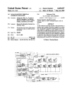
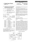
FIG. 1 is a block diagram of the data collection termi
providing input information. The reset control logic 26
nal;
gives the software and ?rmware reset control over the
FIG. 2 is a logic diagram of the interrupt system;
FIG. 3 is a block diagram of the microprocessor
devices coupled to the APCP board 5. The magnetic
wand logic 30 allows a hand-held magnetic wand (not
shown) and a “swipe" reader (not shown) to read infor
interrupt microprogram; and
“FIG. 4 is a timing diagram of the interrupt logic asso
mation on credit cards or similar documents.
ciated with a universal synchronous asynchronous re
ceive transmit communication controller.
The magnetic wand indicator 32 controls the indica
tors on the magnetic wand to give the operator signals
DESCRIPTION OF THE PREFERRED
that the magnetic wand read the information correctly
EMBODIMENT
from the card.
The multifunction reader logic 34 includes interfaces
FIG. 1 is a logic block diagram of a factory data
to a number of devices (not shown) including typically
collection terminal 1. The logic elements are mounted
on two logic boards, a terminal controller board (ATC) 50 a motorized reader. The motorized reader is capable of
reading 80 and 60 column cards as well as 22 column
3 and a personality controller panel board (APCP) 5. A
plastic badges.
number of optional daughter boards 7 may be added to
The display logic 24 controls a one row by 40 charac
the ATC board 3. The ATC board 3 provides the logic
45
for controlling the terminal 1. This logic includes mi
ter display which is capable of displaying the full ASCII
croprocessor 2 which operates with microinstructions
character set in several modes, including a cursor mode,
a mode for inserting or replacing characters, a blinking
and data stored in a random access memory (RAM) and
read only memory (ROM) 4 to control the terminal 1.
The RAM and ROM 4 store up to 32K bytes of RAM
mode or a mode for turning the display on or off.
and 32K bytes of ROM.
The microprocessor 2 is an Intel 8088 central process
ing unit described in the 8086 Family User's Manual,
October 1979 published by Intel Corporation, 3065
Bowers Avenue, Santa Clara, Calif. 95051.
Coupled to the microprocessor 2 are a control bus 13,
keyboard using membrane technology (not shown)
The keyboard logic 22 includes a sealed laminated
which is used for data entry.
The audio-visual indicator logic 20 controls audible
alarms and LED indicators to give the operator infor
mation that the inputs to the terminal 1 were in the
proper format and that the proper input procedures
an address bus 15 and a data/address bus 17. A number 65 were used.
of logic blocks are coupled to busses 15, 17 and 19.
An input/output device 6 provides logic for control
ling an RS232 or an RS422 communication line, a high
The interrupt control logic 18 receives interrupt re
quests from the other control logic blocks on the APCP
board 5 and couples the highest priority device to the
5
4,646,260
6
ATC board 3 for transfer of information between the
device and RAM and ROM 4 under microprocessor 2
control. The interrupt control logic 18 also, under firm
whereby the peripheral device is presenting a status of
punched card or badge in a reader. Microprocessor 2 is
responsive to that interrupt to generate signals which
ware or software control, causes the peripheral devices
to be activated or deactivated.
are decoded to, for example, turn on a card reader
motor or to activate a badge read mechanism.
Bidirectional data bus 1 40 is coupled to the interface
personality logic 8 via a transceiver (XCVR) 14 and
which acts as a master interrupt controller and two
data bus 11. Bidirectional data bus 2 42 is coupled to the
interface personality logic 8 via a transceiver 48 and
data bus 11.
A buffer 46 applies address signals received via an
interrupt controllers. Coupled to the master interrupt
controller 3-24 is the interrupt signal IRQI + for a uni
versal synchronous asynchronous remote transceiver
Terminal 1 includes an interrupt controller 3-24
interrupt controllers 18-2 and 18-4 which act as slave
(USART) 3-16, interrupt signal IRQ2+ for an internal
timer 3-26, interrupt signal IRQ3+ for the bar code
reader 56, interrupt signal IRQ4+ for special 1 logic 58,
and interrupt signal IRQ5+ for special 2 logic 60 pe
ripheral controllers. Note that special 1 logic 58 and
special 2 logic 60 refer to unde?ned peripheral devices
address bus to a device selection 48 which generates a
separate peripheral enable signal for each peripheral
device logic block on the APCP board 5. Only one
peripheral device may be enabled for a data cycle on
data bus 1 40 or data bus 2 42.
A buffer 16 receives control signals from control bus
7 for transfer to the peripheral device. A number of
control signals are transferred to control bus 7 from the
and controllers to be installed in the future.
Interrupt signal MG is applied to interrupt terminal
peripheral devices. These control signals are described 20 IRQO+ of interrupt controller 18-2. Signal MG indi
cates that the magnetic wand logic 30 is ready to trans
infra.
fer data signals to RAM and ROM 4.
A number of peripheral devices are coupled to the
Interrupt signal MGEOR from magnetic wand logic
interface daughter boards 10 via a data bus 21, a XCVR
30 is applied to interrupt terminal IRQ1+ of interrupt
62 and data bus 3 44. These devices include a bar code
reader (not shown) coupled to data bus 3 44 via a bar 25 controller 18-2. Signal MGEOR indicates that the mag
netic wand logic 30 ?nished reading the document.
code reader logic 56 and a number of unspeci?ed de
on the APCP board 5, the three logic blocks, bar code 30
Interrupt signals BD, BIS and BFSI of badge reader
logic 26 are applied to interrupt terminals IRQZ, IRQ3
and IRQ4, respectively, of interrupt controller 18-2.
Signal BD indicates that badge reader logic 26 has data
reader logic 56, special 1 logic 58 and special 2 logic 60,
to transfer to the RAM of RAM and ROM 4. Signal
coupled to the interface daughter boards 10 are
mounted on individual daughter boards which are phys
ically connected to the ATC board 3.
A buffer 52 receives address signals from address bus
23 which are applied to device selection 54. Device
BIS indicates that the badge is inserted in the badge
reader and signal BFSI indicates that the badge is fully
seated in the badge reader.
selection 54 provides enable signals to activate the logic
of a selected daughter board. Peripheral control signals
board logic 22 has data to transfer to the RAM of RAM
and ROM 4.
vices coupled to data bus 3 44 via special 1 logic 56 and
special 2 logic 60. Whereas each of the logic blocks
coupled to the interface personality logic are mounted
Interrupt signal KED is applied to interrupt terminal
IRQS of interrupt controller 18-2 indicating that key
Interrupt signals CBD, CI, TED, COE, CP and CIS
are transferred between the daughter boards and the
40 from multifunction reader logic 34 are applied to inter
interface daughter boards 10 via a control bus 25.
FIG. 2 shows the interrupt operation of the periph
rupt terminals IRQO through IRQS, respectively, of
eral devices. The microprocessor 2 controls the opera
interrupt controller 184. Signal CBD indicates that the
tion of the elements of terminal 1. As an example, if a
multifunction reader logic 34 has data to transfer to
RAM and ROM 4. Signal CI indicates that a card is
peripheral device requires a transfer of information
between RAM and ROM 4 and the device, a unique 45 inserted into the reader. Signal TED indicates that the
signal is generated by the peripheral device. Sensing
trailing edge of the card has passed through the reader.
this signal causes one of the interrupt controllers to
Signal COE indicates that there was a card-oriented
error. Signal CP indicates that a card is present in the
reader. Signal ClS indicates that column one of the card
interrupt the microprocessor 2 which acknowledges the
interrupt. The interrupt controller responds to the ac
knowledge signal by generating a unique vector ad
dress; microprocessor 2 receives the unique vector ad
dress and branches to a microprogram which controls
50 is under the read head of the reader. These interrupt
signals indicate to the microprocessor 2 to start the
reader motor to feed the card when the CI signal is
applied to interrupt controller 18-4 and to stop the
reader motor when the TED signal is applied to the
the information transfer. Other interrupt signals are
generated by the peripheral device to inform the micro
processor 2 that a particular event has occurred, for 55 interrupt controller 184. The CP signal applied to the
interrupt controller 184 results in the interrupt control
example, a badge is inserted in the badge reader. This
ler 18-4 indicating to the microprocessor 2 that the card
conditions the microprocessor 2 to branch to a micro
is in the reader and to await signals C18 and CBD to
program to receive data read from the badge.
transfer data to RAM. The COE signal applied to inter
Since the microprocessor 2 is controlling all of the
functions of terminal 1, the interrupt operation allows 60 rupt controller 184 results in microprocessor 2 branch
ing to an error routine which will delete from the RAM
for efficient control of the terminal 1 by the micro
of RAM and ROM 4 any data stored in memory which
processor 2.
was read from that card and indicates to the operator
The microprocessor 2 processes two classes of inter
that the punched card should be reinserted if the infor
rupts from the peripheral devices. The ?rst class of
interrupt having a higher priority are those operations 65 mation in the punched card is correct.
In the event that a number of the devices requests
whereby data is being transferred between the periph
access to RAM and ROM 4 by generating their respec
eral device and RAM and ROM 4. The second class of
tive interrupt signals, those devices having their inter
interrupt having a lower priority are those operations
4,646,260
7 .
generated by address signals A4+ through A7+ ap
rupt signals coupled to interrupt controller 3-24 receive
?rst or higher priority, those devices having their inter
rupt signals coupled to interrupt controller 18-2 receive
second priority, and those devices having their inter
rupt signals coupled to interrupt controller 18-4 receive
third or lowest priority. Within an interrupt controller,
the IRQO input terminal has highest priority and the
IRQ7 terminal has lowest priority. In summary, signal
IRQI + applied to input terminal IRQI of master inter
rupt controller 3-24 has highest priority and signal ClS
applied to input terminal IRQS of slave interrupt con
troller 184 has the lowest priority of all of the signals
applied to the IRQ input terminals of interrupt control
lers 3-24, 18-21 and 18-3.
The interrupt logic operates in the following manner.
Assume the multifunction reader logic 34 generates
signal COE which is applied to interrupt controller 18-4
indicating that the card is not oriented properly in the
reader. The interrupt controller 18-4 responds by gener
plied to a decoder 3-20 via a register 3-32, signals
AD4+ through AD7+ and microprocessor 2. Signal
A7—, the output of an inverter 34!), enables decoder
3-20. Register 3-32 is enabled by the microprocessor 2
address latch enable signal ALE. Signal IOWR— indi
cates a microprocessor 2 input/output write control
signal which is generated by a microinstruction to cause
a clear interrupt operation. Signal WRITE- and
IOMEM- at logical ZERO applied to a negative
AND gate 3-38 generates the IOWR- signal at logical
ZERO.
Signals DAO and DA] at logical ONE, signals DA2
and DA3 at logical ZERO, and signal DA4 at logical
ONE generates the card error interrupt clear signal
COECL- which is applied to multifunction reader
logic 34 to reset the card error interrupt. The other
clear signals from decoders 18-6 and 18-8 are generated
in a similar manner.
Assume the magnetic wand logic 30 generates an end
ating signal IRQ7+ which is applied to the interrupt
terminal IRQ7 of interrupt controller 3-24. Interrupt
controller 3-24 generates interrupt signal INTR+
of read interrupt signal MGEOR which is applied to
interrupt terminal IRQl of interrupt controller 18-2
which is applied to microprocessor 2 which acknowl
edges the interrupt by generating interrupt acknowl
edge signal INTA—. Interrupt controller 3-24 is re 25
sponsive to signal INTA- by generating CASO, CAS]
ing that microprocessor 2 is conditioned to accept the
interrupt. Interrupt controller 3-24 responds to the fall
and CAS2 identifying the interrupt controller 18-4
which initiated the interrupt request. In response to
signals CASO, CASl and CASZ, interrupt controller
184 generates signal EN2 at logical ZERO which is
applied to a negative OR gate 18-6 to generate output
signal TREN- at logical ZERO which is inverted by
an inverter 34! to signal TREN+. Signal DEN + from
an inverter 3-40 at logical ONE is applied to a NAND
which generates signal IRQ6+. Signal IRQ6+ is ap
plied to interrupt terminal IRQ6 of interrupt controller
3-24. Signal INTR+ interrupts microprocessor 2 which
generates interrupt acknowlege signal INTA- indicat
30
of signal INTA- by generating signals CASO, CASl
and CAS2. Interrupt controller 18-2 responds to signals
CASO, CASl and CAS2 by sending out its vector ad
dress on the data bus. Again XCVR’s 3-28 and 18-8 are
enabled to transfer the vector address to microproces
sor 2. The vector address is stored in register 18-12 on
gate 342 to generate signal KEN-03 at logical ZERO. 35 the rise of the interrupt acknowledge signal INTA-—. In
Signal XEN-03 enables a XCVR 3-28 and a XCVR
18-8. Signal DTREC+ from microprocessor 2 is ap
plied to the direction selection terminals of XCVR’s
18-8 and 3-28 to transfer vector signals generated by
interrupt controller 184 when interrupt controller 184
receives a second interrupt acknowledge signal
INTA- from microprocessor 2, that is, on the fall of
the second INTA- signal. The vector signals IDB
0—7+ are applied to microprocessor 2 via XCVR 18-8,
signals D0-D7, XCVR 3-28, and signals ADO+
through AD7+. Microprocessor 2 uses the vector sig
nals to generate the starting address in RAM and ROM
4 of a microprogram which will process the card-ori
this case, decoder 18-6 is enabled and signal
WGEORCL- is generated to clear the end of read
interrupt, signal WGEOC in magnetic wand logic 30.
A number of peripheral devices generates interrupt
request signals which are applied directly to master
interrupt controller 3-24. Assume that an internal timer
3-26 generates an interrupt signal IRQ2+ when a pre
timed event occurred. The interrupt controller 3-24
generates signal INTR+ to interrupt the microproces
sor 2 which generates the interrupt acknowledge signal
INTA—. The interrupt controller 3-24 responds to the
second occurrence of the fall of signal INTA—- to gen
erate signal INTENB-Ol which enables XCVR 3-30 via
a negative NOR gate 3-36, a NAND gate 344, signal
ented error routine.
For the interrupt clear operation, the vector signals 50 KEN-01 and XCVR 3-30. The direction of the signal
accepted by XCVR 3-30 is speci?ed by transmit receive
IBDO+ through IBD4+ are stored in a register 18-12
signal DTREC+ from microprocessor 2. The interrupt
on the rise of the second interrupt acknowledge signal
controller 3-24 is responsive to the second occurrence
INTA —. Output signals DAO through DA4 are applied
of interrupt acknowledge signal INTA- to generate
to the input terminals of decoders 18-6 and 18-8. Signals
DAO through DA2 applied to select terminals 0, 1 and 55 the 'vector address signals which it sends to micro
processor 2 via signals D0 through D7, XCVR 3-30 and
2 select one of eight output terminals of decoders 18-6
signals ADO+ through AD7+. The vector address
and 18-8. The interrupt clear operation is controlled by
signals are used by the microprocessor 2 to branch to
microprocessor 2 generating signals Y11— and
the ?rst microwords of the microprogram which pro
IOWR- at logical ZERO which are applied to a nega
tive AND gate 18-10. Output signal DIS- at logical 60 cesses the internal timer 3-26. Interrupt signals IRQ3+ ,
IRQ4+ and IRQ5+ are processed in a similar manner
ZERO enables both decoders 18-6 and 18-8. Signal
to the signal IRQ2+ from internal timer 3-26.
'
DA3 at logical ONE applied to terminal G1 of decoder
The interrupt operation of the USART 3-16 operates
18-6 enables decoder 18-6 and signal DA4 at logical
differently than the other peripheral devices in terminal
ONE applied to terminal G1 of decoder 18-8 enables
decoder 18-8. Signal DA3 at logical ONE applied to 65 1 in that USART 3-16 generates its own vector ad
dresses. Note that the interrupt controller generates the
terminal 62A of decoder 18-8 disables decoder 18-8 and
vector address for those peripheral logic units which
signal DA4 at logical ONE applied to terminal 62A of
are coupled to that interrupt controller. Since
decoder 18-6 disables decoder 18-6. Signal Yll- is
9
4,646,260
10
the fall of signal INTA+. Flop 3-4 is a 74Sll2 circuit
element described in the “TTL Data Book for Design
USART’s may generate a number of different vector
addresses representing different modes of operation, the
interrupt operation is speeded up by having the
Engineers", Second Edition, published by Texas Instru
USART generates the'vector address. As an example,
one vector address generated by the USART may point
to a microprogram for processing a communication line
receive transmission, another vector address may point
to a microprogram for processing a communication line
transmit transmission. The USART 3-16 is an Intel 8274
ments, 1976.
During a status write operation, a register ICW2 3-25
in interrupt controller 3-24 and a register ICW2 18-5 in
interrupt controller 18-4 are loaded with the vector
address for the respective 1R0 interrupt terminal. The
outputs of these registers are incremented by the prior
ity position (IRQO through IRQ7) to generate the vec
described in the "Microprocessor and Peripheral Hand
book 1983" published by Intel Corporation.
tor address.
If the USART 3-16 requested access to microproces
To write the initial vector address in register 3-25 of
sor 2, then signal IRQl — which is applied to an inverter
interrupt controller 3-24, microprocessor 2 generates a
number of signals. Address signal All from register 3-32
3-18 is generated. Output signal IRQ+ is applied to the
IRQ1 interrupt terminal of interrupt controller 3-24
which responds by generating microprocessor 2 inter
rupt signal INTR+. Microprocessor 2 generates the
?rst occurrence of interrupt acknowledge signal
indicates a status operation, signal WRITE- indicates
that the interrupt controller 3-24 will receive data, and
INTA - which is received by interrupt controller 3-24.
can equation for DEVS2 is as follows:
signal DEVSZ generated from microprocessor 2 ad
dress signals selects interrupt controller 3-24. The bool
Interrupt controller 3-24 generates the cascade signal 20
CASO at logical ONE and cascade signals CASl and
CASZ at logical ZERO which are applied to a negative
NAND gate 3-12 and a NAND gate 3-14 to generate
where signal IOMEM+ indicates an input/output op
eration and not a RAM and ROM 4 operation. If signal
signal INTENB-02 at logical ZERO and signal IN
TENB+, the output of an inverter 3-8, to logical ONE. 25 READ- is applied to interrupt controller 3-24 in place
of the signal WRITE—, then the contents of register
Signal INTENB+ at logical ONE applied to a negative
ICCWZ 18-3 are transferred to microprocessor 2.
NAND gate 3-10 forces signal IPI— to logical ZERO.
Registers ICW2 18-3 and ICW2 18-5 are loaded in a
This conditions USART 3-16 to respond to the second
occurrence of interrupt acknowledge signal INTA — by
similar manner. Signal Y8- from decoder 3-20 selects
sending the vector address signals D0 through D7 cor 30 interrupt controller 18-4. Again, address signal A0 indi
cates the status mode. Signal WRITE—- is applied to
responding to the operation required by USART 3-16
negative AND gate 338 along with signal IOMEM
to microprocessor 2 via transceiver 3-30. Transceiver
to generate signal IOWR- indicating an input/output
3-30 is enabled by signal INTENB-02 at logical ZERO,
write operation. Signal READ- is applied to negative
negative NOR gate.3-36, NAND gate 3-44 and signal
XEN-Ol at logical ZERO. The direction signal 35 AND gate 3-36 along with signal IOMEM— to gener
DTREC+ conditions XCVR 3-30 to transfer vector
ate signal IORD - including an input/output read oper
address signals D0 through D7 to microprocessor 2 as
ation signal. Signal IOMEM+ is generated by an in
verter 3-37. Signal IOMEM+ is generated by micro
signals ADO+ through AD7+.
Initially, signal IPI— is at logical ZERO to condition
USART 3-16 to generate an interrupt request. Flop 3-4
is reset by signal ORDRST- on “power up” or by
processor 2 to indicate an input/output operation.
FIG. 3 shows a block diagram of the microprocessor
interrupt microprogram. Block 80 shows the micro
processor 2 executing a background microprogram.
microprocessor 2. Output signal ACKl- is at logical
ONE as is interrupt acknowledge signal INTA-,
thereby forcing output signal ACK2—, the output of a
negative AND gate 3-6, to logical ONE. This forces
signal IPI—, the output of negative NAND gate 3-10,
Periodically, decision block 82 is tested to determine
45
if microprocessor interrupt signal INTR+ was gener
ated by interrupt controller 3-24. If signal INTR+ was
not received, then microprocessor 2 continues to exe
cute the background microprogram.
When signal INTR+ is received and tested by deci
sion block 82, the interrupt microprogram branches to
to logical ZERO.
If a device other than USART 3-16 requested an
interrupt of interrupt controller 3-24, then when micro
processor 2 generates the ?rst occurrence of interrupt 50 block 84 which generates the ?rst occurrence of inter
acknowledge signal INTA- in response to interrupt
signal INTR+, interrupt controller 3-24 generates cas
cade signals CASO, CAS1 and CAS2 which address
either interrupt controller 18-2 or 18-4. Signal IN
TENB-02, the output of NAND gate 3-14, is at logical
rupt acknowledge signal INTA—.
Block 86 then generates the second occurrence of
interrupt acknowledge signal INTA—.
Block 88 receives the vector address which is used in
55 block 90 to branch to a microprogram to process in
ONE and signal INTENB+ , the output of inverter 3-8,
is at logical ZERO. The ?rst occurrence of interrupt
acknowledge signal INTA- at logical ZERO is ap
block 92 the particular device requesting the interrupt.
After the interrupt is processed, block 94 generates
signals WRITE- and IOMEM+ to generate signal
IOWR— and address signals A4+ through A7+
plied to an inverter 3-5 to generate signal INTA+ at
logical ONE. Flop 3-4 is set on the fall of signal 60 which are applied to decoder 3-10 to generate signal
Y11—. Signals Y11- and IOWR- are applied to nega
INTA+, that is, as the interrupt acknowledge signal
tive AND gate 18-10 to enable decoders 18-6 and 18-8
INTA- goes to logical ONE. Signal ACKl- is set to
This conditions USART 3-16 to ignore the second oc 65
to generate the clear interrupt signals.
FIG. 4 is a timing diagram showing the interrupt
logic sequence control of the USART 3-16 enable signal
currence of interrupt acknowledge signal INTA—.
IPI—.
However, ?op 3-4 is reset at the end of the second
occurrence of interrupt acknowledge signal INTA — by
IRQ indicates a request by a peripheral device which
is applied to an interrupt controller. INTR+ shows the
logical ZERO forcing signal ACK2- to logical
ZERO, thereby forcing signal IPI— to logical ONE.
11
4,646,260
12
interrupt controller 3-24 to interrupt microprocessor 2.
lNTA— indicates the timing of the interrupt ac
generates said one of said plurality of interrupt
request signals, said interrupt controller means
generating a ?rst plurality of vector address signals
knowledge signal with the ?rst occurrence at A time
on second occurrence of said interrupt acknowl
and the second occurrence at B time.
edge signal when said one of said plurality of ?rst
timing of the interrupt signal INTR+ generated by
devices generated said interrupt request signal;
ACKl- indicates the setting of ?op 3-4 at the time of
the rise of the ?rst occurrence of INTA- and the reset
said one of said at least one second device including
selection means for generating an enable signal
thereby enabling said one of said at least one sec
ond device to generate said one of said plurality of
ting of ?op 3-4 at the time of the rise of the second
occurrence of INTA—.
ACK2- shows the output signal timing of negative
AND gate 3-6. its timing coincides with the timing of
interrupt request signals;
the second occurrence of INTA—.
said selection means being coupled to said interrupt
INTENB+ indicates that USART 3-16 generated
our interrupt request (dotted) and that another device
generated an interrupted request (solid).
IPI- (dotted) indicates that USART 3-16 requested
controller means to receive a ?rst plurality of said
15
an interrupt and IPI- (solid) indicates that USART
3-16 did not request an interrupt and will therefore not
one of said at least one second device and to gener
ate said enable signal on said second occurrence of
respond to the interrupt acknowledge signal INTA—-.
D0 through D7 shows the timing of the vector ad 20
dress sent to microprocessor 2 from interrupt controller
3-24, 18-2, 18-4, or USART 3-16.
Having shown and described a preferred embodiment
of the invention, those skilled in the art will realize that
many variations and modi?cation may be made to affect 25
the described invention and still be within the scope of
the claimed invention. Thus, many of the elements indi
cated above may be altered or replaced by different
elements which will provide the same result and fall
within the spirit of the claimed invention. It is the inten
tion, therefore, to limit the invention only as indicated
by the scope of the claims.
What is claimed is:
1. A data collection terminal comprises:
microprocessor means;
said at least one second device being coupled to a
said at least one second device generating one of a
plurality of interrupt request signals on said one of
said plurality of interrupt request signal lines when
said one of said plurality of ?rst devices and said at
least one second device requires said microproces 45
sor means to process an interrupt;
interrupt controller means coupled to said each of
said plurality of interrupt signal lines for receiving
said one of said plurality of interrupt request signals
and generating a microprocessor interrupt signal,
said each of said plurality of interrupt signal lines
microprocessor means to receive said interrupt
vices generated said interrupt request signal and
said second vector address signals from said one of
said second devices when said one of said at least
one second device generated said interrupt request
signal for branching to a microprogram to process
the interrupt.
said plurality of interrupt request signals from said
communication controller for generating said mi
croprocessor interrupt signal when said communi
cation controller requires said microprocessor
rupt controller means being coupled to said inter
nal timer and receiving a second of said plurality of
interrupt request signals from said internal timer
dance with a terminal of said interrupt controller
means to which said each of said plurality of inter 55
acknowledge signal for generating a plurality of
address signals from said interrupt controller
means when said one of said plurality of ?rst de
means to process the interrupt, said master inter
being coupled to said interrupt controller means
establishing a predetermined priority in accor
edge signal when said microprocessor means is
ready to process the interrupt;
said interrupt controller means being coupled to said
interrupt acknowledge signal;
said microprocessor means receiving said ?rst vector
wherein said predetermined priority of said communi
respective one of a plurality of interrupt request
signal lines, one of said plurality of ?rst devices and
and a second occurrence of an interrupt acknowl
plurality of vector address signals on receipt of said
enable signal and said second occurrence of said
cation controller is a ?rst priority.
3. The terminal of claim 2 wherein said plurality of
?rst devices includes an internal timer having a second
priority and a bar code reader having a third priority.
4. The terminal of claim 3 wherein said interrupt
controller means comprises:
master interrupt controller means coupled to said
communication controller and receiving a first of
device, each of said plurality of ?rst devices and
said microprocessor means being coupled to said
interrupt controller means for receiving said mi
croprocessor interrupt signal and generating a ?rst
said interrupt acknowledge signal, said one of said
at least one second device generating a second
2. The terminal of claim 1 wherein said at least one
35 second device includes a communication controller
a plurality of ?rst devices and at least one second
rupt signal lines is coupled;
plurality of cascade signals when said one of said at
least one second device generated said interrupt
request signal and on receipt thereof to address said
for generating said microprocessor interrupt signal
when said internal timer requires said microproces
sor means to process the interrupt, said master
interrupt controller means being coupled to said
bar code reader and receiving a third of said plural
ity of interrupt request signals for generating said
microprocessor interrupt signal when said bar code
reader requires said microprocessor means to pro
cess the interrupt.
5. The terminal of claim 4 wherein said ?rst and said
second occurrence of said interrupt acknowledge signal
65 each has a leading edge at the start of the signal and a
cascade signals on ?rst occurrence of said interrupt
trailing edge at the ?nish of the signal.
acknowledge signal when said one of said plurality
6. The terminal of claim 5 wherein said selection
means comprises:
of ?rst devices and said at least one second device
13
4,646,260
14
flip ?op being set by said trailing edge of said ?rst
occurrence of said interrupt acknowledge signal
thereby generating said third acknowledge signal
?rst selection means for generating a ?rst acknowl
edge signal in a second state prior to said ?rst oc
currence of said interrupt acknowledge signal; and
second selection means coupled to said ?rst selection
means and responsive to said ?rst acknowledge
signal in said second state for generating said en
able signal in a ?rst state, said communication con
in a ?rst state;
a negative AND gate coupled to receive said third
acknowledge signal in said second state for gener
ating said ?rst acknowledge signal in said second
troller being responsive to said enable signal in said
?rst state for generating said one of said plurality of
state, and coupled to receive said third acknowl
edge signal in said ?rst state and said ?rst occur
interrupt request signals if said communication
rence of said interrupt acknowledge signal for gen
erating said ?rst acknowledge signal in said ?rst
controller requires said microprocessor means to
process said interrupt.
state.
7. The terminal of claim 6 wherein said ?rst selection
means generates said ?rst acknowledge signal in a sec
ond state after said ?rst and said second occurrences of
12. The terminal of claim 11 wherein said third selec
tion means comprises:
a ?rst negative NAND gate coupled to receive a
said interrupt acknowledge signal.
8. The terminal of claim 7 wherein said selection
means further comprises:
third selection means coupled to receive a ?rst plural
ity of cascade signals addressing said one of said at 20
least one second device for generating a second
acknowledge signal in a second state.
9. The terminal of claim 8 wherein said second selec
tion means is coupled to receive said second acknowl
edge signal in said second state for generating said en 25
able signal in said ?rst state, said communication con
troller being coupled to receive said enable signal in said
?rst state and said second occurrence of said interrupt
second cascade signal in a ?rst state and a third
cascade signal in a ?rst state for generating a fourth
cascade signal in a second state;
a positive NAND gate coupled to receive a ?rst cas
cade signal in a second state and said fourth cas
cade signal in said second state for generating said
select signal in a ?rst state; and
an inverter coupled to receive said select signal in
said ?rst state for generating said second acknowl
edge signal in said second state;
said ?rst cascade signal in said second state and said
second and said third cascade signals in said ?rst
state forming said ?rst plurality of said plurality of
acknowledge signal for generating said second plurality
30
of vector address signals.
10. The terminal of claim 9 wherein said third selec
tion means is coupled to receive a second plurality of
cascade signals for generating said second acknowledge
signal in a ?rst state, said second selection means being
cascade signals.
13. The terminal of claim 12 wherein said second
selection means comprises:
a second negative NAND gate coupled to receive
said ?rst acknowledge signal in said second state or
said second acknowledge signal in said second state
for generating said enable signal in said ?rst state.
coupled to receive said second acknowledge signal in
said ?rst state for generating said enable signal in a
second state, said communication controller being cou
pled to receive said enable signal in said second state for
14. The terminal of claim 13 wherein said ?rst selec
tion means is shared by said each of said at least one
second device and, wherein said selection means in
cludes a plurality of said second and said third selection
means, one of said plurality of said second and said third
selection means being associated with said each of said
not responding to said second occurrence of said inter
rupt acknowledge signal.
11. The terminal of claim 10 wherein said ?rst selec
tion means comprises:
a flip ?op having means for resetting and generating
at least one second device.
i
a third acknowledge signal in a second state, said
45
50
55
65
1'
t
l
t