1
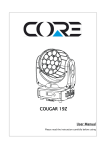
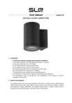
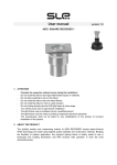
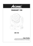
AEDI WASH GLOBUS 90 TW User Manual Please read the instructions carefully before use Version 1.0 CONTENTS 1. SAFETY INSTRUCTION ...................................................................................... 2 2. ABOUT THE PRODUCT ....................................................................................... 4 3. TECHNICAL SPECIFICATIONS ........................................................................ 4 4. ACCESSORIES ....................................................................................................... 5 5. HOW TO SET THE FIXTURE ............................................................................. 6 5.1 CONTROL PANEL ......................................................................................... 6 5.2 MAIN FUNCTIONS........................................................................................ 7 6. HOW TO CONTROL THE UNIT ....................................................................... 13 6.1 DMX controller .............................................................................................. 13 6.2 DMX 512 configuration................................................................................. 15 7. DMX512 CONNECTIONS................................................................................... 16 8. TROUBLESHOOTING ........................................................................................ 17 9. FIXTURE CLEANING AND MAINTANCE ..................................................... 18 1 1. SAFETY INSTRUCTION WARNING Please read the instructions carefully which includes important information about the installation, operation and maintenance. Please keep this User Guide for future consultation. If you sell the unit to another user, be sure that they also receive this instruction booklet. Caution: All fixtures are intact from the manufacturer, please operate follow up the user manual, artificial fault are not under guarantee repair. Unpack and check carefully that there is no transportation damage before using the unit per first time. DO install and operate by operator. Use safety chain when fixes the unit. The unit must be installed in a location with adequate ventilation, at least 50cm from adjacent surfaces. Before operating, ensure that the voltage and frequency of power supply match the power requirements of the unit. It’s important to ground the yellow/green conductor to earth in order to avoid electric shock. Maximum ambient temperature Ta: 40°C. DO NOT operate it where the temperature is higher than this. DO NOT connect the device to any dimmer pack. Make sure there are no flammable materials close to the unit while operating, as it is fire hazard. Look over power wires carefully, replace immediately if there is any damage. Unit surface temperature may reach up to 60°C. DO NOT touch the housing bare-hand during its operation. 2 Avoid any inflammable liquids, water or metal objects entering the unit. Once it happens, cut off the mains power immediately. DO NOT operate in dirty and dusty environment, also cleaning fixtures regularly. DO NOT allow children to operate the fixture. DO NOT touch any wire during operation as there might be a hazard of electric shock. Avoid power wires together around other cables. Replace fuse only with the same type. In the event of serious operating problem, stop using the unit immediately. The housing and the lenses must be replaced if they are visibly damaged. DO NOT open the unit as there are no user serviceable parts inside. Never try to repair the unit by yourself. Repairs carried out by unskilled people can lead to damage or malfunction. Please contact the nearest authorized technical assistance center. If you use a 230V 50Hz power supply, DO NOT connect in series more than 12 units; use another main supply for the next 12 fixtures. If you use a 120V 60Hz power supply, DO NOT connect in series more than 6 units; use another main supply for the next 6 fixtures. The manufacturer does not take responsibility if the device is operated under conditions other than described in this manual. The product may suffer damage and the guarantee becomes void. Installation: The unit should be mounted via its screw holes on the bracket. Always ensure that the unit is firmly fixed to avoid vibration and slipping while operating. Always ensure that the structure to which you are attaching the unit is secure and is able to support a weight of 10 times of the unit’s weight. Also always use a safety cable that can hold 12 times of the weight of the unit when installing the fixture in the air. The equipment must be fixed by professionals. And it must be fixed at a place where is out of the touch of people and has no one pass by or under it. 3 2. ABOUT THE PRODUCT The stylishly modern and unassuming exterior of AEDI WASH GLOBUS houses state-of-the-art TUNABLE WHITE LED technology and made using the highest quality materials and construction methods. Bringing the flexibility to outdoor application, this powerful lighting fixture is ideally suited to use in landscape and building illumination, and IP66 ensures safe operation in even the most demanding areas. With integral built-in AC/DC power supply of 230V AC. 3. TECHNICAL SPECIFICATIONS - OMS R&D specialists have designed this fixture to replace the traditional outdoor 400W discharge fixtures. - Proper thermal management with active cooling system and heavy duty design to ensure reliable performance under harsh environment - It features 90pcsx3W CREE WW/CW LEDs provides powerful output and excellent color mixing. - Great built-in programs for instant light shows. - Different optical systems, ideal for different applications – for the illumination of buildings, bridges, stadium, landscapes, theme parks and more. - Die-cast housing and thermal management for the reliable performance. - Power Electronics using 1 kHz refreshing frequency, flicker-free under HD camera 4 Mounting: Optical systems: Manual Tilt Adjustable Bracket 6° / 15° / 25°/ 40°/ 60°/ 80° Light Source: 90 ×3W WW/CW CREE LEDs LED color variants: TUNABLE WHITE 2900 to 5700K Lumen Output: > 9000 lm Input Voltage: 100-240V AC 50/60Hz Daisy Chain System Wiring: Dimmable Electronic Control Gear USITT DMX 512 A Power Consumption: Max. 267 W / Average consumption in color mixing mode 140 W Power cable connection: IP rated connectors Service lifetime: 50,000 hrs. / L70 /@ 25°C Operating ambient tem: -20°C/+40°C Materials: Housing: die-cast aluminum. Cover: clear hardened glass. IP Rating: IP66 Dimension: 399× 400×195mm Weight: 16.4 kg Finishing: White aluminum. (RAL 9006). Accessories: DMX controllers: AEDITEMPA ATTACA & AEDITEMPA LIBA 4. ACCESSORIES - Power Extension Cable 1, 2, 5, 10 m. - DMX Extension Cable 1, 2, 5, 10 m. 5 5. HOW TO SET THE FIXTURE 5.1 CONTROL PANEL 1. Display: To show the various menus and the selected functions Button: 2. MENU To select the programming functions 3. DOWN To go backward in the selected functions 4. UP To go forward in the selected functions 5. ENTER To confirm the selected functions 6. POWER IN: Water proof connectors for power input 7. POWER OUT: Water proof connectors for power output 8. DMX IN: Water proof 3-pin XLR connectors for DMX 512 operation 9. DMX OUT: Water proof connectors for DMX 512 operation with 3-pin XLR plug 6 5.2 MAIN FUNCTIONS To select any functions, press the MENU button until the required one is shown on the display. Select the function by the ENTER button and the display will blink. Use the DOWN and UP button to change the mode. Once the required mode has been selected, press the ENTER button to setup or it will automatically return to the main functions without any change after idling one minute. Back to the functions without any change press the MENU button. The main functions are shown below: Once you set to , after running in show mode for 5 minutes without any change or restarting the unit, the key board become locked. Press the ENTER button to enable the menu, the display will show , press the UP and DOWN button until it shows , then press the ENTER to unlock. 7 8 DMX 512 Address Setting Select the , press the ENTER button and the display will blink. Use the DOWN and UP button to change the DMX 512 address. Once the address has been selected, press the ENTER button to setup or automatically exit menu mode without any change after one minute. Back to the previous functions without any change press the MENU button. Channel mode Select the , press the ENTER button and the display will blink. Use the DOWN and UP button to select the (4 Channels), (5 Channels)or (7 Channels) Mode. Once select, press the ENTER button to setup or automatically exit menu mode without any change after one minute. To go back to the functions without any change press the MENU button. Show mode It allows you to select among the built-in programs Select the , press the ENTER button and the display will blink. Use the DOWN and UP button to select the (show 1)…. button to setup. press the ENTER button, (show 19). Once select, press the ENTER will blinking on the display, use DOWN and UP button adjust the fade time (0~255), press the ENTER button to store and will blinking on the display, use the DOWN and UP button adjust the white time (0~255), press the ENTER button to store or automatically return to the main functions without any change after one minute. To go back to the previous functions without any change press the MENU button. Blackout mode Select the , press the ENTER button and the display will blink. Use the DOWN and UP button to select the (blackout) or (normal). Once selected, press the ENTER button to setup or automatically exit menu mode without any change after one minute. To go back to the functions without any change press the MENU button. 9 Program Shows Press the MENU button up to when the button and select the is shown on the display. Press the ENTER mode, Press the ENTER button and the display will blink. Use the DOWN and UP button to select the (Show 18)or (Show 17) , (Show 19). Once the show has been selected, press the ENTER button to enter program setting. Use the DOWN and UP button to select (length, the steps, you choose from the total amount of steps, you want to run, for example, if the total amount of steps you set is 50, you can choose only first 1-10 steps to run). (white) and (step), select to set (color) and (dimmer) for every step. Automatically return to the main functions without any change after one minute. To go back to the previous functions without any change press the MENU button. Manual Mode Press the MENU button up to when the is shown on the display. Press the ENTER button and the display will blink. Use the DOWN and UP button to select the (Green), (Blue), (White), (Dimmer) or (Red), (Strobe). Once selected, press the ENTER button to setup, then use the DOWN and UP button to adjust the value (0~255) or automatically exit menu mode without any change after one minute. To go back to the functions without any change press the MENU button. White Balance Press the MENU button up to when the is showing on the display. Pressing the ENTER button and the display will blink. Use the DOWN and UP button to select the (Red), (Green),or (Blue)mode. Once the mode has been selected, press the ENTER button to setup or automatically return to the main functions without any change after one minute. To go back to the previous functions without any change press the MENU button. 10 Display Inversion Press the MENU button up to when the is showing on the display. Pressing the ENTER button and the display will blink. Use the DOWN and UP button to select the (normal) (inverse),Once the mode has been selected, press the ENTER button to setup or or automatically return to the main functions without any change after one minute. To go back to the previous functions without any change press the MENU button. DMX Control Mode Press the MENU button up to when the is shown on the display. Pressing the ENTER (DMX button and the display will blink. Use the DOWN and UP button to select the control)or (manual control),Once select, press the ENTER button to setup。If (Flash mode), is selected, use the DOWN and UP button to select (Green), (Blue), (White), (Cyan), (White), (Macro)or (Yellow), (Red), (Purple), (fade),press the ENTER button to confirm, then use the DOWN and UP button to adjust the dimmer(1…9). Notice: (flash mode)is selected,press the ENTER button to confirm, then use the DOWN and If UP button to select the (wait time) or (shutter), Once select, press the ENTER button to confirm. then use the DOWN and UP button to adjust the the wait time or shutter speed(solw ,midum, fast)(1…..9). Once select, press the ENTER button to store or automatically return to the main functions without any change after one minute. To go back to the previous functions without any change press the MENU button. 1. If (flash mode)is selected,press the ENTER button to confirm, then use the DOWN and UP button to select the (wait time) or (strobe), Once select, press the ENTER button to confirm. then use the DOWN and UP button to adjust the the wait time or strobe speed (solw ,middle, fast) (1…..9). Once select, press the ENTER button to store or automatically return to the main functions without any change after one minute. To go back to 11 the previous functions without any change press the MENU button。 2. If (flash mode)is selected, press the ENTER button to confirm, then use the DOWN and UP button to adjust the type of the rotation(1…..9). Once select, press the ENTER button to store or automatically return to the main functions without any change after one minute. To go back to the previous functions without any change press the MENU button. 3. If (fade)is selected, press the ENTER button to confirm, then use the DOWN and UP button to adjust rotation time(1…..9). Once select, press the ENTER button to store or automatically return to the main functions without any change after one minute. To go back to the previous functions without any change press the MENU button. Key Board Lock Press the MENU button up to when the is showing on the display. Pressing the ENTER button and the display will blink. Use the DOWN and UP button to select the (lock the (normal),Once select, press the ENTER button to setup or automatically key board)or return to the main functions without any change after one minute. Back to the previous functions press the MENU button. Auto Test Press the MENU button up to when the, is blinking on the display. Pressing the ENTER button and the unit will run self-test by built-in program. To go back to the functions press the MENU button again. LED Press the MENU button up to when the is shown on the display. Pressing ENTER button and the display will blink. Use DOWN and UP button to select (display on)or (display off 20 seconds after exit menu)mode. Once select, press ENTER button to setup or exit menu mode without any change after one minute. Back to the functions without any change press MENU button again. 12 Temperature Test Press the MENU button up to when the is blinking on the display. Pressing ENTER button and the display will show the temperature of the unit. To go back to the functions press the MENU button again. Fixture Hours Press the MENU button up to when the is blinking on the display. Pressing ENTER button and the display will show the number of working hours of the unit. To go back to the functions press the MENU button. Software version Press the MENU button up to when the is blinking on the display. Pressing ENTER button and the display will show the version of software of the unit. To go back to the functions press the MENU button again. 6. HOW TO CONTROL THE UNIT You can operate the unit by DMX controller: No need to turn the unit off when you change the DMX address, as new DMX address setting will be affected at once. Every time you turn the unit on, it will show on the display After that the unit will be ready to receive DMX signal or run the built in programs. 6.1 DMX Controller Use universal DMX controller to control the units, you have to set DMX address from 1 to 512 channel so that the units can receive DMX signal. Press the MENU button up to when the is showing on the display. Pressing ENTER button and the display will blink. Use DOWN and UP button to change the DMX512 address. Once the address has been selected, press and keep ENTER button pressed up to when the display stops 13 blinking or storing automatically 8 seconds later. To go back to the functions without any change press the MENU button again. Please refer to the following diagram to address your DMX512 channel for the first 4 units: 14 6.2 DMX 512 Configuration 4/5/7 Channels Mode: 15 7. DMX512 CONNECTIONS 1. If you use a controller with 5 pins DMX output, you need to use a 5 to 3 pin adapter-cable. 2. Connect the unit together in a `daisy chain` by XLR plug from the output of the unit to the input of the next unit. The cable can not branched or split to a `Y` cable. DMX 512 is a very high-speed signal. Inadequate or damaged cables, soldered joints or corroded connectors can easily distort the signal and shut down the system. 3. The DMX output and input connectors are pass-through to maintain the DMX circuit, when one of the units’ power is disconnected. 4. Each lighting unit needs to have an address set to receive the data sent by the controller. The address number is between 0-511 (usually 0 & 1 are equal to 1). 5. The end of the DMX 512 system should be terminated to reduce signal errors. 6. 3 pin XLR connectors are more popular than 5 pin XLR. 16 3 pin XLR: Pin 1: GND, Pin 2: Negative signal (-), Pin 3: Positive signal (+) 5 pin XLR: Pin 1: GND, Pin 2: Negative signal (-), Pin 3: Positive signal (+), Pin 4/Pin 5: Not used. 8. TROUBLESHOOTING Following are a few common problems that may occur during operation. Here are some suggestions for easy troubleshooting: Problem Possible Cause The unit does not work, no light. Incorrect power cable connection. The unit does not respond properly to the DMX control. Action Check the connection of power. Incorrect mains voltage. Measure the mains voltage on the main connector. Incorrect DMX cable connection. Check DMX connectors and cables to see if link properly. Repair or replace damaged wires. Incorrect address assignment to the units. Check the addresses of the units and the protocol settings. Unfinished data connection. Insert a terminal plug in the output jack of the last unit of the connection. It has been set up an operating mode different from the DMX mode used. Check the operating mode set up. Try to use another DMX controller. 17 9. FIXTURE CLEANING AND MAINTANCE The cleaning of outside glass must be carried out periodically to optimize light output. Cleaning frequency depends on the environment in which the fixture operates: damp, smoky or particularly dirty surrounding can cause greater accumulation of dirt on the fixture’s optics. Clean with soft cloth using normal glass cleaning fluid. Always dry the parts carefully. Clean the external optics at least every 20 days. Version 1.0 Specifications are subject to change without notice. 18 Declaration of Conformity We declare that our products (lighting equipments) comply with the following specification and bears CE mark in accordance with the provision of the Electromagnetic Compatibility (EMC) Directive 89/336/EEC. EN55103-1: 2009 ; EN55103-2: 2009; EN62471: 2008; EN61000-3-2: 2006 + A1:2009 + A2:2009; EN61000-3-3: 2008. & Harmonized Standard EN 60598-1:2008 + All:2009; EN 60598-2-17:1989 + A2:1991; EN 62471:2008; EN 62493: 2010 Safety of household and similar electrical appliances Part 1: General requirements WWW.SLEPROJECTS.COM © 2014. All specifications subject to change without notice 19