1
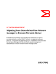
AP-7532 Access Point
INSTALLATION GUIDE
2
AP-7532 Access Point
Zebra and the Zebra head graphic are registered trademarks of ZIH Corp. The Symbol logo is a registered
trademark of Symbol Technologies, Inc., a Zebra Technologies company.
© 2015 Symbol Technologies, Inc.
Installation Guide
1.0 Introduction . . . . . . . . . . . . . . . . . . . . . . . . . . . . . . . . . . . . . . . . . . . . . . . 5
1.1 Document Conventions . . . . . . . . . . . . . . . . . . . . . . . . . . . . . . . . . . . . . 5
1.2 Warnings . . . . . . . . . . . . . . . . . . . . . . . . . . . . . . . . . . . . . . . . . . . . . . . . 6
1.3 Site Preparation . . . . . . . . . . . . . . . . . . . . . . . . . . . . . . . . . . . . . . . . . . . 6
1.4 AP-7532 Package Contents . . . . . . . . . . . . . . . . . . . . . . . . . . . . . . . . . . 6
1.4.1 Features . . . . . . . . . . . . . . . . . . . . . . . . . . . . . . . . . . . . . . . . . . . . . 6
1.5 AP-7532 Antennas . . . . . . . . . . . . . . . . . . . . . . . . . . . . . . . . . . . . . . . . . 7
2.0 Hardware Installation . . . . . . . . . . . . . . . . . . . . . . . . . . . . . . . . . . . . . . . 8
2.1 Installation Instructions . . . . . . . . . . . . . . . . . . . . . . . . . . . . . . . . . . . . . 8
2.2 Precautions . . . . . . . . . . . . . . . . . . . . . . . . . . . . . . . . . . . . . . . . . . . . . . . 8
2.3 Access Point Placement . . . . . . . . . . . . . . . . . . . . . . . . . . . . . . . . . . . . . 9
2.4 Power Injector System . . . . . . . . . . . . . . . . . . . . . . . . . . . . . . . . . . . . . . 9
2.5 Wall Mount Instructions . . . . . . . . . . . . . . . . . . . . . . . . . . . . . . . . . . . 11
2.5.1 Wall Mount Procedure - New Installation . . . . . . . . . . . . . . . . . 12
2.5.2 Wall Mount Procedure - Existing Access Point Replacement . . 13
2.6 Suspended Ceiling T-Bar Mount Installation . . . . . . . . . . . . . . . . . . . 14
2.7 LED Indicators . . . . . . . . . . . . . . . . . . . . . . . . . . . . . . . . . . . . . . . . . . . 17
3.0 Basic Access Point Configuration . . . . . . . . . . . . . . . . . . . . . . . . . . . 19
4.0 AP-7532 Access Point Specifications . . . . . . . . . . . . . . . . . . . . . . . . 30
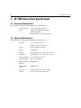
4.1 Electrical Characteristics . . . . . . . . . . . . . . . . . . . . . . . . . . . . . . . . . . . 30
4.2 Physical Characteristics . . . . . . . . . . . . . . . . . . . . . . . . . . . . . . . . . . . . 30
4.3 Radio Characteristics . . . . . . . . . . . . . . . . . . . . . . . . . . . . . . . . . . . . . . 31
5.0 Regulatory Information . . . . . . . . . . . . . . . . . . . . . . . . . . . . . . . . . . . . . 32
5.1 Regulatory Information . . . . . . . . . . . . . . . . . . . . . . . . . . . . . . . . . . . . 32
5.2 Wireless Device Country Approvals . . . . . . . . . . . . . . . . . . . . . . . . . . 32
5.2.1 Country Selection . . . . . . . . . . . . . . . . . . . . . . . . . . . . . . . . . . . . 33
5.2.2 Frequency of Operation - FCC and IC . . . . . . . . . . . . . . . . . . . . . 33
5.3 Health and Safety Recommendations . . . . . . . . . . . . . . . . . . . . . . . . . 34
5.3.1 Warnings for the use of Wireless Devices . . . . . . . . . . . . . . . . . 35
3
4
AP-7532 Access Point
5.3.2 Potentially Hazardous Atmospheres - Fixed Installations . . . . . . 35
5.3.3 Safety in Hospitals . . . . . . . . . . . . . . . . . . . . . . . . . . . . . . . . . . . 35
5.4 RF Exposure Guidelines . . . . . . . . . . . . . . . . . . . . . . . . . . . . . . . . . . . . 36
5.4.1 Safety Information . . . . . . . . . . . . . . . . . . . . . . . . . . . . . . . . . . . . 36
5.4.2 International . . . . . . . . . . . . . . . . . . . . . . . . . . . . . . . . . . . . . . . . 36
5.4.3 EU . . . . . . . . . . . . . . . . . . . . . . . . . . . . . . . . . . . . . . . . . . . . . . . . . 36
5.4.4 US and Canada . . . . . . . . . . . . . . . . . . . . . . . . . . . . . . . . . . . . . . 36
5.5 Power Supply . . . . . . . . . . . . . . . . . . . . . . . . . . . . . . . . . . . . . . . . . . . . 37
5.6 Radio Frequency Interference Requirements - FCC . . . . . . . . . . . . . . . 37
5.6.1 Radio Transmitters - Part 15 . . . . . . . . . . . . . . . . . . . . . . . . . . . . 37
5.6.2 Radio Frequency Interference Requirements - Canada . . . . . . . . 37
5.7 CE Marking and European Economic Area (EEA) . . . . . . . . . . . . . . . . . 38
5.8 Statement of Compliance . . . . . . . . . . . . . . . . . . . . . . . . . . . . . . . . . . . 39
5.9 Japan (VCCI) - Voluntary Control Council for Interference . . . . . . . . . 39
5.10 Korea Warning Statement for Class B ITE . . . . . . . . . . . . . . . . . . . . . 39
5.11 Other Countries. . . . . . . . . . . . . . . . . . . . . . . . . . . . . . . . . . . . . . . . . . 39
5.12 Waste Electrical and Electronic Equipment (WEEE) . . . . . . . . . . . . . 41
5.13 Turkish WEEE Statement of Compliance . . . . . . . . . . . . . . . . . . . . . . 42
6.0 Support . . . . . . . . . . . . . . . . . . . . . . . . . . . . . . . . . . . . . . . . . . . . . . . . . . 43
7.0 Symbol Technologies End-User Software License Agreement . . 44
8.0 AP-7532 Access Point China ROHS Compliance . . . . . . . . . . . . . . . 51
Installation Guide
1
5
Introduction
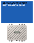
The AP-7532 external antenna and internal antenna Access Point’s are mid-tier Access Point’s with a relatively
small footprint which supports functionality for dependable and efficient network performance.The AP-7532 is a
3x3:3 802.11ac Access Point utilizing one 2.4 GHz 802.11n radio and one 5 GHz 802.11ac radio. The Access Point
housing is Plenum-rated (UL2043).
The Access Point’s unique WiNG 5 software enables the Access Point to function as either a Standalone Access
Point, an Adaptive Access Point, or a Virtual Controller.
If new to Access Point technology, refer to the WiNG Access Point System Reference Guide to familiarize yourself
with Access Point technology and the feature set supported by the WiNG operating system. The guide is available
at www.zebra.com/support.
This document is written for the qualified network device installer.
1.1 Document Conventions
The following graphical alerts are used in this document to indicate notable situations:
NOTE
!
Tips, hints, or special requirements that you should take note of.
CAUTION
Care is required. Disregarding a caution can result in data loss or
equipment malfunction.
WARNING! Indicates a condition or procedure that could result in personal injury or
equipment damage.
6
AP-7532 Access Point
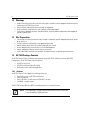
1.2 Warnings
•
•
•
•
Read all installation instructions and site survey reports, and verify correct equipment installation before
connecting the AP-7532 Access Point.
Remove jewelry and watches before installing this equipment.
Verify any device connected to this unit is properly wired and grounded.
Verify there is adequate ventilation around the device, and that ambient temperatures meet equipment
operation specifications.
1.3 Site Preparation
•
•
•
•
•
•
Consult your site survey and network analysis reports to determine specific equipment placement, power
drops, and so on.
Assign installation responsibility to the appropriate personnel.
Identify and document where all installed components are located.
Ensure adequate, dust-free ventilation to all installed equipment.
Identify and prepare Ethernet and console port connections.
Verify cable lengths are within the maximum allowable distances for optimal signal transmission.
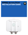
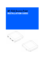
1.4 AP-7532 Package Contents
An AP-7532 Access Point is available in both external antenna (AP-7532) and internal antenna (AP-7532I)
configurations. An AP-7532 ships with the following:
•
•
•
AP-7532 Access Point
AP-7532 Installation Guide (This Guide)
Wall mount screws and mounting bracket
1.4.1 Features
An AP-7532 Access Point supports the following feature set:
•
•
•
•
Two RJ-45 connectors (GE1/POE and Console)
Two LED indicators
One 2.4 GHz 802.11n radio and one 5 GHz 802.11ac radio
3x3 MIMO, 3 spatial streams
The GE1/POE accepts 802.3at or 802.3af compliant power from an external source.
NOTE
When operating in a Gigabit Ethernet environment, CAT-5e or CAT-6 cable
is recommended for Gigabit operation.
Installation Guide
7
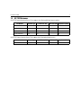
1.5 AP-7532 Antennas
An AP-7532 external antenna Access Point supports the following dual band antenna options:
Part Number
Antenna Type
2.4 GHZ Gain (dBi)
5 GHZ Gain (dBi) Impedance (Ohms)
ML-2452-APA2-01
Dipole
3.17
4.6
50
ML-2452-HPA5-036
Dipole
3
5
50
ML-2452-APAG2A1-01
Dipole
2.7
1.7
50
ML-2452-PNA5-01R
Panel
5.5
6
50
An AP-7532 internal antenna Access Point supports the following dual band antenna:
Part Number
BIRCH-INT-ANT
Antenna Type
Monopole
2.4 GHZ Gain (dBi)
4.13
5 GHZ Gain (dBi) Impedance (Ohms)
5.92
N/A
8
AP-7532 Access Point
2
Hardware Installation
2.1 Installation Instructions
An AP-7532 Access Point mounts either on a wall (with M 3.5 x 0.6 x 23 MM pan head screws and mounting
bracket- or equivalent) or on a suspended ceiling T-bar.
To prepare for the installation:
1. Match the part number on the purchase order with the part numbers in the packing list and on the case
of the Access Point.
2. Verify the contents of the box include the intended AP-7532 Access Point, and the included hardware
matches the package contents (see AP-7532 Package Contents on page 6).
Part Number
Description
AP-7532-67040-US
AP-7532 dual radio 802.11ac 3x3:3 MIMO Access Point external antenna US version
AP-7532-67040-WR
AP-7532 dual radio 802.11ac 3x3:3 MIMO Access Point external antenna International version
AP-7532-67040-EU
AP-7532 dual radio 802.11ac 3x3:3 MIMO Access Point external antenna EU version
AP-7532-67030-US
AP-7532 dual radio 802.11ac 3x3:3 MIMO Access Point internal antenna US version
AP-7532-67030-WR
AP-7532 dual radio 802.11ac 3x3:3 MIMO Access Point internal antenna International version
AP-7532-67030-EU
AP-7532 dual radio 802.11ac 3x3:3 MIMO Access Point internal antenna EU version
3. Review site survey and network analysis reports to determine the location and mounting position for the
AP-7532 Access Point.
4. Connect a CAT-5 or better Ethernet cable to a compatible 802.3at or 802.3af power source and run the
cable to the installation site. Ensure there is sufficient slack on the cable to perform the installation
steps.
NOTE
When operating in a Gigabit Ethernet environment, CAT-5e or CAT-6 cable
is recommended for Gigabit operation.
2.2 Precautions
Before installing an AP-7532 Access Point, verify the following:
•
Your are using the correctly rated power solution for the AP-7532 (either the AP-PSBIAS-2P3-ATR power
injector or the PWRS-14000-54R external power supply)
• Do not to install the AP-7532 in wet or dusty areas.
• Verify the environment has a continuous temperature range between -4° F to 104° F/-20° C to 40° C for
external antenna Access Points and 32° F to 104° F/0° C to 40° C for internal antenna Access Points.
Installation Guide
9
2.3 Access Point Placement
For optimal performance, install the Access Point away from transformers, heavy-duty motors, fluorescent lights,
microwave ovens, refrigerators and other industrial equipment. Signal loss can occur when metal, concrete, walls
or floors block transmission. Install the Access Point in an open area or add Access Points as needed to improve
coverage.
Antenna coverage is analogous to lighting. Users might find an area lit from far away to be not bright enough. An
area lit sharply might minimize coverage and create dark areas. Uniform antenna placement in an area (like even
placement of a light bulb) provides even, efficient coverage.
Install the Access Point at an ideal height of 10 feet from the ground.
To maximize the Access Point’s radio coverage area, recommends conducting a site survey to define and document
radio interference obstacles before installing the Access Point.
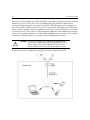
2.4 Power Injector System
An AP-7532 Access Point can receive power via an Ethernet cable connected to the GE1/POE (LAN) port.
When users purchase a WLAN solution, they often need to place Access Points in obscure locations. In the past, a
dedicated power source was required for each Access Point in addition to the Ethernet infrastructure. This often
required an electrical contractor to install power drops at each Access Point location. The Power Injector merges
power and Ethernet into one cable, reducing the burden of installation and allowing optimal Access Point
placement in respect to the intended coverage area.
!
CAUTION
Using a non-compliant injector, or an injector supporting legacy modes
will not allow the AP-7532 to function at optimum performance levels.
!
CAUTION
Do not plug the AP-PSBIAS-2P3-ATR Power Injector into the Access
Point’s Console port. Connecting the Power Injector into the console
port can damage the port and void the AP-7532’s product warranty.
The AP-7532’s supported Power Injector (Part No. AP-PSBIAS-2P3-ATR) is a high power POE Injector delivering up
to 30 watts. The Access Point can only use a Power Injector when connecting the unit to the Access Point’s GE1/POE
port. The Power Injector is separately ordered and not shipped with an existing AP SKU.
10
AP-7532 Access Point
The Access Point Power Supply (Part No. PWRS-14000-54R) is not included with the Access Point and is orderable
separately as an accessory. If the Access Point is provided both POE power and PWRS-14000-54R power
concurrently, the Access Point will source power from the PWRS-14000-54R supply only. Disconnecting the AC
power from the PWRS-14000-54R causes the Access Point to re-boot before sourcing power from the POE power
injector. If the AP is operating using injector supplied power, the AP will not automatically reboot if an AC adapter
is connected. The Access Point continues to operate with power supplied from the AC adapter without change to
the Access Point operating configuration. If using AC adapter supplied power and a change to the AP’s operating
configuration is warranted, the Access Point needs to be manually rebooted by the customer.
!
CAUTION
The Access Point supports any standards-based compliant power
source. However, using the wrong solution (including a POE system
used on a legacy Access Point) could either limit functionality or
severely damage the Access Point and void the product warranty.
A separate Power Injector is required for each AP-7532 Access Point comprising the network.
Installation Guide
11
The Power Injector can be installed free standing, on an even horizontal surface or wall mounted using the power
injector’s wall mounting key holes. The following guidelines should be adhered to before cabling the Power Injector
to an Ethernet source and an Access Point:
•
•
•
!
!
Do not block or cover airflow to the Power Injector.
Keep the Power Injector away from excessive heat, humidity, vibration and dust.
The Power Injector isn’t a repeater, and does not amplify the Ethernet signal. For optimal performance,
ensure the Power Injector is placed as close as possible to the data port.
CAUTION
To avoid problematic performance and restarts, disable POE from a
wired switch port connected to an Access Point if mid-span power
sourcing equipment (PSE) is used between the two, regardless of the
manufacturer of the switch.
CAUTION
Ensure AC power is supplied to the Power Injector using an AC cable
with an appropriate ground connection approved for the country of
operation.
To install the Power Injector to an Ethernet data source and an Access Point:
1. Connect the Power Injector to an AC outlet (110VAC to 220VAC).
2. Connect an RJ-45 Ethernet cable between the Power Injector Data & Power Out connector and the
Access Point’s GE1/POE port.
3. Connect an RJ-45 Ethernet cable between the network data supply (host) and the Power Injector Data In
connector.
Ensure the cable length from the Ethernet source (host) to the Power Injector and Access Point does not
exceed 100 meters (333 ft).
The Power Injector has no On/Off power switch. The Injector receives power and is ready for device
connection and operation as soon as AC power is applied. Refer to the Installation Guide shipped with the
Power Injector for a description of the device’s LEDs.
2.5 Wall Mount Instructions
A wall mount deployment requires hanging the AP-7532 Access Point with the provided mounting bracket and two
screws. The AP-7532 can be mounted on to any plaster, wood or cement wall surface using the provided mounting
bracket.
The hardware required to install the AP-7532 on a wall consists of:
• Two wide-shoulder Phillips pan head self-tapping screws (M3.5 x 0.6 x 23 mm)
• Mounting bracket
Optional customer provided installation tools include:
• Phillips head screw driver, or drill and drill bit
12
AP-7532 Access Point
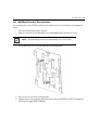
2.5.1 Wall Mount Procedure - New Installation
This section describes a new AP-7532 installation with no previous Access Point existing on the intended wall
surface.
1. Place the mounting bracket against the wall.
2. Mark the screw hole locations depending on the intended deployment orientation of the unit.
NOTE
When pre-drilling a hole the recommended hole size is 4mm (0.16in.).
3. At each point, drill a hole in the wall and attach the mounting bracket.
4. Place the Access Point on the mounting bracket.
5. Cable the Access Point using either the Power Injector solution (AP-PSBIAS-2P3-ATR) or the approved
AP-7532 power supply (PWRS-14000-54R).
Installation Guide
13
For Power Injector installations:
a. Connect a RJ-45 CAT5e (or CAT6) Ethernet cable between the Power Injector Data & Power Out
connector and the Access Point’s GE1/POE port.
b. Connect a RJ-45 CAT5e (or CAT6) Ethernet cable between the network data supply (host) and the
Power Injector Data In connector.
c. Ensure the cable length from the Ethernet source (host) to the Power Injector and
Access Point does not exceed 100 meters (333 ft). The Power Injector has no On/Off power switch.
The Power Injector receives power as soon as AC power is applied.
For standard power adapter (non Power Injector) and line cord installations:
a. Connect a RJ-45 Ethernet cable between the network data supply (host) and the Access Point’s
GE1/POE port.
b. Verify the power adapter is correctly rated according to the country of operation.
c. Connect the power supply line cord to the power adapter.
d. Attach the power adapter cable into the power connector on the Access Point.
e. Attach the power supply line cord to a power supply.
6. Verify the Access Point is receiving power by observing the LEDs are lit or flashing. For more information
on AP-7532 LED behavior, see LED Indicators on page 17.
7. The Access Point is ready to configure.
CAUTION
!
If not using an AP-PSBIAS-2P3-ATR power injector, ensure only the
AP-7532’s designated power supply (PWRS-14000-54R) is used to
supply power to the Access Point. Using an incorrectly rated power
supply could damage the Access Point and void the product warranty.
Do not actually connect to the power source until the cabling portion
of the installation is complete.
2.5.2 Wall Mount Procedure - Existing Access Point Replacement
An existing AP-7131 or AP-7131N Series Access Point installed on a wall can be replaced by an AP-7532. Simply
remove the existing AP-7131 or AP-7131N and install the new provided mounting bracket for AP-7532 directly to
the wall. The cabling procedure for such a replacement is as described in the previous section.
14
AP-7532 Access Point
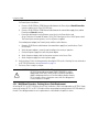
2.6 Suspended Ceiling T-Bar Mount Instructions
Ceiling mount requires holding the AP-7532 up against a T-bar of a suspended ceiling grid and twisting the unit on
to the T-bar. If deploying the AP-7532 on a sculpted ceiling T-Bar, the Access Point mounting kit (Part No.
KT-135628-01) can optionally be used as well.
1. First install the mounting bracket on the T-bar then attach the mounting bracket using the mounting slots
on the Access Point.
2. Cable the Access Point using either the Power Injector solution (AP-PSBIAS-2P3-ATR) or the approved
AP-7532 power supply (PWRS-14000-54R).
Installation Guide
15
For Power Injector installations:
a. Connect a RJ-45 CAT5e (or CAT6) Ethernet cable between the network data supply (host) and the
Power Injector Data In connector.
b. Connect a RJ-45 CAT5e (or CAT6) Ethernet cable between the Power Injector Data & Power Out
connector and the Access Point’s GE1/POE port.
c. Ensure the cable length from the Ethernet source (host) to the Power Injector and
Access Point does not exceed 100 meters (333 ft). The Power Injector has no On/Off power switch.
The Power Injector receives power as soon as AC power is applied.
For standard power adapter (non Power Injector) and line cord installations:
a. Connect a RJ-45 Ethernet cable between the network data supply (host) and the Access Point’s
GE1/POE port.
b. Verify the power adapter is correctly rated according the country of operation.
c. Connect the power supply line cord to the power adapter.
d. Attach the power adapter cable into the power connector on the Access Point.
e. Attach the power supply line cord to a power supply.
CAUTION
!
3.
If not using an AP-PSBIAS-2P3-ATR power injector, ensure only the
AP-7532’s designated power supply (PWRS-14000-54R) is used to
supply power to the Access Point. Using an incorrectly rated power
supply could damage the Access Point and void the product warranty.
Do not actually connect to the power source until the cabling portion
of the installation is complete.
Verify the unit has power by observing the LEDs. For more information on AP-7532 LED behavior, see LED
Indicators on page 17.
4.
5.
6.
7.
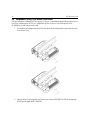
Align the bottom of the ceiling T-bar with the back of the Access Point.
Orient the Access Point chassis by its length and the length of the ceiling T-bar.
Rotate the Access Point chassis 45 degrees clockwise.
Push the back of the Access Point chassis on to the bottom of the ceiling T-bar.
16
AP-7532 Access Point
8.
Rotate the Access Point chassis 45 degrees counter-clockwise. The clips click as they fasten to the T-bar.
9.
The Access Point is ready to configure.
Installation Guide
17
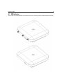
2.7 LED Indicators
The AP-7532 LED activity indicators are located on the front of the housing and are visible through the enclosure.
18
AP-7532 Access Point
The LEDs provide a status display indicating error conditions, transmission, and network activity for the 5 GHz
802.11ac (amber) radio and the 2.4 GHz 802.11n (green) radio.
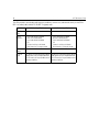
Task
5 GHz Activity LED (Amber)
2.4 GHz Activity LED (Green)
Unconfigured On
Radio
On
Normal
Operation
• If this radio band is enabled:
Blink at 5 second interval
• If this radio band is disabled:
Off
• If there is activity on this band:
Blink interval at 1 time per second
• If this radio band is enabled:
Blink at 5 second interval
• If this radio band is disabled:
Off
• If there is activity on this band:
Blink interval at 1 time per second
Firmware
Update
On
Off
Locate AP
Mode
LEDs blink in an alternating green, red and
amber pattern using an irregular blink rate.
This LED state in no way resembles normal
operating conditions.
LEDs blink in an alternating green, red and
amber pattern using an irregular blink rate.
This LED state in no way resembles normal
operating conditions
Installation Guide
3
19
Basic Access Point Configuration
Once the AP-7532 is installed and powered on, complete the following steps to get the Access Point up and running
and access management functions:
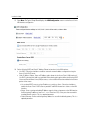
1. The Access Point’s IP address is optimally provided using DHCP. A zero config IP address can also be
derived if DHCP resources are unavailable. Using zero config, the last two octets in the IP address are the
decimal equivalent of the last two bytes in the Access Point’s hardcoded MAC address.
For example:
MAC address - 00:C0:23:00:F0:0A
Zero-config IP address - 169.254.240.10
To derive the Access Point’s IP address using its MAC address:
a. Open the Windows calculator by selecting Start > All Programs > Accessories > Calculator. This menu
path may vary slightly depending on your version of Windows.
b. With the Calculator displayed, select View > Scientific. Select the Hex radio button.
c. Enter a hex byte of the Access Point’s MAC address. For example, F0.
d. Select the Dec radio button. The calculator converts F0 into 240. Repeat this process for the last
Access Point MAC address octet.
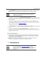
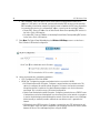
2. Point the Web browser to the Access Point’s IP address. The following login screen displays:
20
AP-7532 Access Point
3. Enter the default username admin in the Username field.
4. Enter the default password admin123 in the Password field.
5. Click the Login button to load the management interface.
NOTE
When logging in for the first time, you’re prompted to change the
password to enhance device security in subsequent logins.
NOTE
If you get disconnected when running the wizard, you can connect again
with the Access Point’s actual IP address (once obtained) and resume the
wizard.
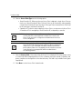
6. If this is the first time the management interface has been accessed, the Initial Setup Wizard
automatically displays.
Installation Guide
NOTE
21
The Initial Setup Wizard displays the same pages and content for each
Access Point type supported. The only difference being the number of
radios configurable by Access Point type, as an AP7131 Access Point can
support up to three radios, AP6522, AP6532, AP6562, AP8132 and
AP7161 Access Points support two radios and AP6511 and AP6521
Access Points support a single radio.
The Introduction screen displays the various actions that can be performed using the wizard under the
Function Highlight field.
Use the Choose One type to Setup the Access Point field options to select the type of wizard to run.
The Typical Setup is the recommended wizard. This wizard uses the default parameters for most of the
configuration parameters and sets up a working network with the least amount of manual configuration.
The Advanced Setup wizard is for administrators who prefer more control over the different
configuration parameters. A few more configuration screens are available for customization when the
Advanced Setup wizard is used.
The first page of the Initial Setup Wizard displays the Navigation Panel and Function Highlights for
the configuration activities comprising the Access Point's initial setup. This page also displays options to
select the typical or advanced mode for the wizard.
The Navigation Panel for the Typical Setup Wizard displays the basic configuration options.
A green checkmark to the left of an item in the Navigation Panel defines the task as having its minimum
required configuration set correctly. A red X defines a task as still requiring at least one parameter be
defined correctly.
22
AP-7532 Access Point
7. Select Save/Commit within each page to save the updates made to that page's configuration. Select
Next to proceed to the next page listed in the Navigation Panel without saving your updates.
NOTE
While you can navigate to any page in the navigation panel, you cannot
complete the Initial AP Setup Wizard until each task in the Navigation
Panel has a green checkmark.
For the purposes of this guide, use the Typical Setup (Recommended) option to simplify the process of
getting the Access Point up and running quickly with a minimum number of changes to the Access Point’s
default configuration.
For information on using the Access Point’s Advanced Setup option, refer to the WiNG Access Point
System Reference Guide to familiarize yourself with the feature set supported by the WiNG operating
system. The guide is available at www.zebra.com/support.
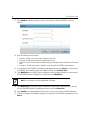
To configure the Access Point using the Typical Setup Wizard:
8. Select Typical Setup from the Choose One type to Setup the Access Point field on the Initial Setup
Wizard.
9. The Typical Setup Wizard displays the Access Point Settings screen to define the Access Point's
Standalone versus Virtual Controller AP functionality. This screen also enables selection of the country of
operation for the Access Point.
NOTE The professional installer should refer to the WiNG Access Point System
Reference Guide available at www.zebra.com/support for detailed
information on how to set the Access Point’s transmit power, antenna gain
and channel in respect to the delployment country’s unique regulatory
requirements.
Installation Guide
23
10. Select an Access Point Type from the following options:
• Virtual Controller AP - When more than one Access Point is deployed, a single Access Point can
function as a Virtual Controller AP. Up to 24 Access Points can be connected to, and managed by,
a single Virtual Controller AP of the same Access Point type. These connected Access Points must
be the same type as the Virtual Controller AP.
• Standalone AP - Select this option to deploy this Access Point as an autonomous fat Access Point.
A Standalone AP isn't managed by a Virtual Controller AP, or adopted by a controller.
NOTE If wanting to adopt the Access Point to a controller or service platform,
use the controller or service platform’s resident UI to connect to the
Access Point, provision its configuration and administrate the Access
Point’s configuration.
NOTE If designating the Access Point as a Standalone AP, its recommended the
Access Point’s UI be used exclusively to define its device configuration,
and not the CLI. The CLI provides the ability to define more than one
profile and the UI does not. Consequently, the two interfaces cannot be
used collectively to manage profiles without an administrator
encountering problems.
11. Select the Country Code of the country where the Access Point is deployed. Selecting a proper country
is a critical task while configuring the Access Point, as it defines the correct channels of operation and
ensures compliance to the regulations of the selected country. This field is only available for the Typical
Setup Wizard.
12. Select Next to set the Access Point’s network mode.
24
AP-7532 Access Point
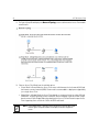
13. The Typical Setup Wizard displays the Network Topology screen to define how the Access Point handles
network traffic.
14. Select an Access Point Mode from the available options.
• Router Mode -In Router Mode, the Access Point routes traffic between the local network (LAN) and
the Internet or external network (WAN). Router mode is recommended in a deployment supported by
just a single Access Point.
• Bridge Mode - In Bridge Mode, the Access Point depends on an external router for routing LAN and
WAN traffic. Routing is generally used on one device, whereas bridging is typically used in a larger
density network. Select Bridge Mode when deploying this Access Point with numerous peer Access
Points supporting clients on both the 2.4GHz and 5GHz radio bands.
NOTE When Bridge Mode is selected, WAN configuration cannot be performed
and the Typical Setup Wizard does not display the WAN configuration
screen.
Installation Guide
25
15. Select Next. The Typical Setup Wizard displays the LAN Configuration screen to set the Access Point's
LAN interface configuration.
16. Set the following DHCP and Static IP Address/Subnet information for the LAN interface:
• Use DHCP - Select the checkbox to enable an automatic network address configuration using the
Access Point’s DHCP server.
• Static IP Address/Subnet - Enter an IP Address and a subnet for the Access Point's LAN interface. If
Use DHCP is selected, this field is not available. When selecting this option, define the following DHCP
Server and Domain Name Server (DNS) resources, as those fields will become enabled on the bottom
portion of the screen.
• Use on-board DHCP server to assign IP addresses to wireless clients - Select the checkbox to
enable the Access Point’s DHCP server to provide IP and DNS information to clients on the LAN
interface.
• Range - Enter a starting and ending IP Address range for client assignments on the LAN interface.
Avoid assigning IP addresses from x.x.x.1 - x.x.x.10 and x.x.x.255, as they are often reserved for
standard network services. This is a required parameter.
• Default Gateway - Define a default gateway address for use with the default gateway. This is a
required parameter.
26
AP-7532 Access Point
• DNS Forwarding - Select this option to allow a DNS server to translate domain names into IP
addresses. If this option is not selected, a primary and secondary DNS resource must be specified.
DNS forwarding is useful when a request for a domain name is made but the DNS server, responsible
for converting the name into its corresponding IP address, cannot locate the matching IP address.
• Primary DNS - Enter an IP Address for the main Domain Name Server providing DNS services for
the Access Point's LAN interface.
• Secondary DNS - Enter an IP Address for the backup Domain Name Server providing DNS services
for the Access Point's LAN interface.
17. Select Next. The Typical Setup Wizard displays the Wireless LAN Setup screen to set the Access
Point’s Wireless LAN interface configuration.
18. Set the following WLAN1 Configuration parameters:
• SSID - Configure the SSID for the WLAN.
• WLAN Type - Configure the encryption and authentication to use with this WLAN.
• No Authentication and No Encryption - Configures a network without any authentication. This
option also configures the network without encryption. This means that any data transmitted
through the network is in plain text. Any device between end points can see the information
transmitted. This is the least secure of all network configurations.
• Captive Portal Authentication and No Encryption - Configures a network that uses a RADIUS server
to authenticate users before allowing them on to the network. Once on the network, no encryption
is used for the data being transmitted through the network. Select this option to use a Web page
(either internally or externally hosted) to authenticate users before access is granted to the
network.
• PSK authentication, WPA2 encryption - Configures a network that uses PSK authentication and
WPA2 encryption. Select this option to implement a pre-shared key that must be correctly shared
between the Access Point and requesting clients using this WLAN.
Installation Guide
27
19. Select Next. The Typical Setup Wizard displays the RADIUS Server Configuration screen if required.
Otherwise, the Typical Setup Wizard displays the Summary and Commit screen.
20. Use the Radius Server Configuration screen to configure the users for the onboard RADIUS server. Use
the screen to add, modify and remove RADIUS users.
28
AP-7532 Access Point
21. Select Add User to display the dialog to enter user information to add to the RADIUS server user
database.
22. Enter the following user information:
• Username - Provide a user name used to authenticate the user.
• Password - Provide a password used to authenticate the user.
• Confirm Password - Confirm the password by entering the same password as entered in the Password
field.
• Description - Provide a description to identify the user created in the RADIUS server database.
23. To create the entry in the RADIUS server database and add another user, select Create. To create the entry
in the RADIUS server database and close the Add User dialog, select Create & Close.
24. Select Modify User on the RADIUS Server Configuration screen to modify information for an existing user
from the RADIUS database. Highlight the user entry then select Modify User.
NOTE The Username cannot be modified with this dialog.
25. Select Delete User on the RADIUS Server Configuration screen to remove information for an existing
user from the RADIUS database. Highlight the user entry and select Delete User.
26. Select Confirm on the dialog displayed. The entry for the user is removed from the RADIUS database.
27. To dismiss the dialog without adding, modifying or removing entries in the RADIUS server database, select
Cancel.
Installation Guide
29
28. Select Next. The Typical Setup Wizard displays the Summary and Commit screen to summarize the
screens (pages) and settings updated using the Typical Setup Wizard.
No user intervention or additional settings are required. Its an additional means of validating the Access
Point’s updated configuration before it’s deployed. However, if a screen displays settings not intended as
part of the initial configuration, then any screen can be selected again from within the Navigation Panel
and its settings modified accordingly.
If the configuration displays as intended, select Save/Commit to implement these settings to the Access
Point’s configuration. If additional changes are warranted based on the summary, either select the target
page from the Navigational Panel, or use the Back and Next buttons to scroll to the target screen.
30
4
AP-7532 Access Point
AP-7532 Access Point Specifications
4.1 Electrical Characteristics
An AP-7532 Access Point has the following electrical characteristics:
Operating Current &
Voltage
12VDC, 1.25A (AUX input voltage)
12VDC PWRS-14000-54R power supply
48VDC, 0.375A (POE)
802.3at AP-PSBIAS-2P3-ATR Power Injector
4.2 Physical Characteristics
An AP-7532 Access Point has the following physical characteristics:
Dimensions
7.1 in. L x 6.5 in. W x 1.6 in. H
180 mm L x 165 mm W x 41 mm H
Housing
Plenum-rated housing (UL2043)
Weight
1.8 lbs/0.82 kg
Operating
Temperature
External antennas: -4° F to 104° F/-20° C to 40° C
Internal antennas: 32° F to 104° F/0° C to 40° C
Storage Temperature
-40° F to 158° F/-40° C to 70° C
Operating Humidity
85% RH non-condensing
Operating Altitude
(maximum)
8,000 ft @ 28C
Storage Altitude
(maximum)
30,000 ft @ 12C
Electrostatic
Discharge
External antennas: 12KV air, 6 KV contact
Internal antenna: 15KV air, 8KV contact
Installation Guide
31
4.3 Radio Characteristics
The AP-7532 Access Point has the following radio characteristics:
Data Rates Supported 802.11b/g: 1,2,5.5,11,6,9,12,18,24,36,48 and 54 Mbps
802.11a: 6,9,12,18,24,36,48, and 54 Mbps 802.11n: MCS 0-23 up to
450 Mbps
802.11ac: MCS 0-9 up to 1.3 Gbps
Wireless Medium
Direct Sequence Spread Spectrum (DSSS)
Orthogonal Frequency Division Multiplexing (OFDM)
Spatial multiplexing (MIMO)
Network Standards
IEEE 802.11a/b/g/n/ac
802.11d and 802.11i WPA2
WMM and WMM-UAPSD
Transmit Power
Adjustment
1dB increments
32
5
AP-7532 Access Point
Regulatory Information
5.1 Regulatory Information
This guide applies to the following Model Numbers: AP-7532, AP-7532I.
Zebra devices are designed to be compliant with rules and regulations in locations they are sold and will be labeled
as required.
Local language translations are available at the following Website: www.zebra.com/support
Any changes or modifications to Symbol equipment, not expressly approved by Zebra could void the user's authority
to operate the equipment.
Zebra devices are professionally installed, the Radio Frequency Output Power will not exceed the maximum
allowable limit for the country of operation.
Antennas: Use only the supplied or an approved replacement antenna. Unauthorized antennas, modifications, or
attachments could cause damage and may violate regulations.
This device is only to be used with a Zebra Wireless Switch.
Declared maximum operating temperature: 40°C.
5.2 Wireless Device Country Approvals
Regulatory markings, subject to certification, are applied to the device signifying the radio(s) is/are approved for
use in the following countries: United States, Canada, Japan, China, S. Korea, Australia, and Europe 1
Please refer to the Declaration of Conformity (DoC) for details of other country markings. This is available at:
www.zebra.com/doc
Note: For 2.4GHz or 5GHz Products: Europe includes, Austria, Belgium, Bulgaria, Czech Republic, Cyprus, Denmark,
Estonia, Finland, France, Germany, Greece, Hungary, Iceland, Ireland, Italy, Latvia, Liechtenstein, Lithuania,
Luxembourg, Malta, Netherlands, Norway, Poland, Portugal, Romania, Slovak Republic, Slovenia, Spain, Sweden,
Switzerland and the United Kingdom.
Operation of the device without regulatory approval is illegal.
Installation Guide
33
5.2.1 Country Selection
Select only the country in which you are using the device. Any other selection will make the operation of this device
illegal. Some Access Points are specifically designed to operate in certain countries (Example; -US for the United
States, -EU for the European Union).
Country Roaming
This device incorporates the International Roaming feature (IEEE802.11d) which will ensure the product operates
on the correct channels for the particular country of use.
5.2.2 Frequency of Operation – FCC and IC
5 GHz Only
Industry Canada Statement:
Caution: The device for the band 5150-5250 MHz is only for indoor usage to reduce potential for harmful
interference to co-Channel mobile satellite systems. High power radars are allocated as primary users (meaning
they have priority) of 5250-5350 MHz and 5650-5850 MHz and these radars could cause interference and/or
damage to LE-LAN devices.
Avertissement: Le dispositif fonctionnant dans la bande 5150-5250 MHz est réservé uniquement pour une
utilisation à l'intérieur afin de réduire les risques de brouillage préjudiciable aux systèmes de satellites mobiles
utilisant les mêmes canaux.
Les utilisateurs de radars de haute puissance sont désignés utilisateurs principaux (c.-à-d., qu'ils ont la priorité)
pour les bands 5250-5350 MHz et 5650-5850 MHz et que ces radars pourraient causer du brouillage et/ou des
dommages aux dispositifs LAN-EL.
2.4 GHz Only
The available channels for 802.11bg operation in the US are Channels 1 to 11. The range of channels is limited by
firmware.
Indoor Use
This device was designed for Indoor use.
34
AP-7532 Access Point
5.3 Health and Safety Recommendations
Ergonomic Recommendations
Caution: In order to avoid or minimize the potential risk of ergonomic injury follow the recommendations below.
Consult with your local Health & Safety Manager to ensure that you are adhering to your company's safety
programs to prevent employee injury.
•
•
•
•
•
•
•
•
•
•
•
Reduce or eliminate repetitive motion
Maintain a natural position
Reduce or eliminate excessive force
Keep objects that are used frequently within easy reach
Perform tasks at correct heights
Reduce or eliminate vibration
Reduce or eliminate direct pressure
Provide adjustable workstations
Provide adequate clearance
Provide a suitable working environment
Improve work procedures
Vehicle Installation
RF signals may affect improperly installed or inadequately shielded electronic systems in motor vehicles (including
safety systems). Check with the manufacturer or its representative regarding your vehicle. You should also consult
the manufacturer of any equipment that has been added to your vehicle.
An air bag inflates with great force. DO NOT place objects, including either installed or portable wireless
equipment, in the area over the air bag or in the air bag deployment area. If in-vehicle wireless equipment is
improperly installed and the air bag inflates, serious injury could result.
Position your device within easy reach. Be able to access your device without removing your eyes from the road.
Note: Connection to an alert device that will cause a vehicle horn to sound or lights to flash, on receipt of a call on
public roads, is not permitted.
IMPORTANT
Before installing or using, check state and local laws regarding windshield mounting and use of equipment.
For Safe installation
• Do not put your phone in a location that obstructs the drivers vision or interferes with the operation of
the Vehicle.
• Do not cover an airbag.
Installation Guide
35
Safety on the Road
Do not take notes or use the device while driving. Jotting down a "to do" list or flipping through your address book
takes attention away from your primary responsibility, driving safely.
When driving a car, driving is your first responsibility - Give full attention to driving. Check the laws and
regulations on the use of wireless devices in the areas where you drive. Always obey them.
5.3.1 Warnings for the use of Wireless Devices
Please observe all warning notices with regard to the usage of wireless devices.
5.3.2 Potentially Hazardous Atmospheres – Fixed Installations
You are reminded of the need to observe restrictions on the use of radio devices in fuel depots, chemical plants etc.
and areas where the air contains chemicals or particles (such as grain, dust, or metal powders).
5.3.3 Safety in Hospitals
Wireless devices transmit radio frequency energy and may affect medical electrical equipment. When
installed adjacent to other equipment, it is advised to verify that the adjacent equipment is not adversely
affected.
Pacemakers
Pacemaker manufacturers recommended that a minimum of 15cm (6 inches) be maintained between a handheld
wireless device and a pacemaker to avoid potential interference with the pacemaker. These recommendations are
consistent with independent research and recommendations by Wireless Technology Research.
Persons with Pacemakers:
•
Should ALWAYS keep the device more than 15cm (6 inches) from their pacemaker when turned ON.
•
Should not carry the device in a breast pocket.
•
Should use the ear furthest from the pacemaker to minimize the potential for interference.
•
If you have any reason to suspect that interference is taking place, turn OFF your device.
Other Medical Devices
Please consult your physician or the manufacturer of the medical device, to determine if the operation of your
wireless product may interfere with the medical device.
36
AP-7532 Access Point
5.4 RF Exposure Guidelines
5.4.1 Safety Information
Reducing RF Exposure - Use Properly
Only operate the device in accordance with the instructions supplied.
5.4.2 International
The device complies with internationally recognized standards covering human exposure to electromagnetic fields
from radio devices. For information on “International” human exposure to electromagnetic fields refer to the
Declaration of Conformity (DoC) at: www.zebra.com/doc.
5.4.3 EU
Remote and Standalone Antenna Configurations
To comply with EU RF exposure requirements, antennas that are mounted externally at remote locations or
operating near users at stand-alone desktop of similar configurations must operate with a minimum separation
distance of 25cm from all persons.
5.4.4 US and Canada
Co-located statement
To comply with FCC RF exposure compliance requirements, the antenna used for this transmitter must not be
co-located or operating in conjunction with any other transmitter/antenna except those already approved in this
filling.
To satisfy US and Canadian RF exposure requirements, a transmitting device must operate with a minimum
separation distance of 25cm or more from a person's body.
Pour satisfaire aux exigences Américaines et Canadiennes d'exposition aux radiofréquences, un dispositif de
transmission doit fonctionner avec une distance de séparation minimale de 25cm ou plus de corps d'une personne.
Radiation Exposure Statement
This equipment complies with IC radiation exposure limits set forth for an uncontrolled environment. This
equipment should be installed and operated with minimum distance 25cm between the radiator and your body.
NOTE IMPORTANTE: (Pour l'utilisation de dispositifs mobiles)
Déclaration d'exposition aux radiations:
Cet équipement est conforme aux limites d'exposition aux rayonnements IC établies pour un environnement non
contrôlé. Cet équipement doit être installé et utilisé avec un minimum de 25cm de distance entre la source de
rayonnement et votre corps.
Remote and Standalone Antenna Configurations
To comply with FCC RF exposure requirements, Antennas that are mounted externally must be professionally
installed at a fixed location and operate with a minimum distance of 25cm from all persons.
Installation Guide
37
To comply with FCC Antenna requirements, the Antenna must be adjusted such that the RF emission lobes are
below 30 degrees elevation.
5.5 Power Supply
This device must be powered from a 802.3af or 802.3at compliant power source which has been certified by the
appropriate agencies, or by an approved UL LISTED ITE (IEC/EN 60950-1, LPS/SELV) power supply with electrical
ratings: Output 12 Vdc, min 1.25 A or 48 Vdc min 0.375 A (POE), with a recommended ambient temperature greater
than 40 degrees C. Use of alternative power supply will invalidate any approvals given to this unit and may be
dangerous.
5.6 Radio Frequency Interference Requirements—FCC
This equipment has been tested and found to comply with the limits for a Class B digital device,
pursuant to Part 15 of the FCC rules. These limits are designed to provide reasonable protection
against harmful interference in a residential installation. This equipment generates, uses and can
radiate radio frequency energy and, if not installed and used in accordance with the instructions,
may cause harmful interference to radio communications. However there is no guarantee that interference will not
occur in a particular installation. If this equipment does cause harmful interference to radio or television reception,
which can be determined by turning the equipment off and on, the user is encouraged to try to correct the
interference by one or more of the following measures:
•
•
•
•
Reorient or relocate the receiving antenna
Increase the separation between the equipment and receiver
Connect the equipment into an outlet on a circuit different from that to which the receiver is connected
Consult the dealer or an experienced radio/TV technician for help.
5.6.1 Radio Transmitters (Part 15)
This device complies with Part 15 of the FCC Rules. Operation is subject to the following two conditions: (1) this
device may not cause harmful interference, and (2) this device must accept any interference received, including
interference that may cause undesired operation.
5.6.2 Radio Frequency Interference Requirements - Canada
CAN ICES-3 (B)/NMB-3(B)
Radio Transmitters
For RLAN Devices:
The use of 5 GHz RLAN’s, for use in Canada, have the following restrictions:
•
Restricted Band 5.60 – 5.65 GHz
This device complies with RSS 210 of Industry Canada. Operation is subject to the following two conditions: (1)
this device may not cause harmful interference and (2) this device must accept any interference received,
including interference that may cause undesired operation.
38
AP-7532 Access Point
Le présent appareil est conforme aux CNR d'Industrie Canada applicables aux appareils radio exempts de licence.
L'exploitation est autorisée aux deux conditions suivantes : (1) l'appareil ne doit pas produire de brouillage, et (2)
l'utilisateur de l'appareil doit accepter tout brouillage radioélectrique subi, même si le brouillage est susceptible
d'en compromettre le fonctionnement.
Label Marking: The Term "IC:" before the radio certification only signifies that Industry Canada technical
specifications were met
In accordance with the regulations of Industry Canada, this radio transmitter can operate with an antenna of a
type and a maximum gain (or lower) approved for the transmitter by Industry Canada. With the aim of reducing the
risk of radio interference to other users, the chosen antenna type and its gain should be selected so that the
equivalent isotropically radiated power (e.i.r.p.) does not exceed the intensity necessary for the establishment of a
satisfactory connection.
Conformément à la réglementation d'Industrie Canada, le présent émetteur radio peut fonctionner avec une
antenne d'un type et d'un gain maximal (ou inférieur) approuvé pour l'émetteur par Industrie Canada. Dans le but
de réduire les risques de brouillage radioélectriqueà l'intention des autres utilisateurs, il faut choisir le type
d'antenne et son gain de sorte que la puissance isotrope rayonnée équivalente (p.i.r.e.) ne dépasse pas l'intensité
nécessaire àl'établissement d'une communication satisfaisante.
In compliance with respective local regulatory law, AP software provides professional installers the option to
configure the antenna type and antenna gain for approved antennas.
This radio transmitter (AP-7532, AP-7532I) has been approved by Industry Canada to operate with the antenna
types listed below and having a maximum gain allowable and the impedance required for each type of antenna.
The antenna types not included in this list, or whose gain is higher than the maximum gain indicates, are strictly
prohibited for the operation of the transmitter.
Refer to AP-7532 Antennas on page 7 for a listing of the 2.4 GHz and 5 GHz antennas initially approved for use
with AP-7532 and AP7532I Access Points.
Le présent émetteur radio (AP-7532, AP-7532I) a été approuvé par Industrie Canada pour fonctionner avec les
types d'antenne énumérés ci-dessous et ayant un gain admissible maximal et l'impédance requise pour chaque
type d'antenne. Les types d'antenne non inclus dans cette liste ou dont le gain est supérieur au gain maximal
indiqué, sont strictement interdits pour l'exploitation de l'émetteur.
5.7 CE Marking and European Economic Area (EEA)
WARNING: This is a Class B product. In a domestic environment this product may cause radio interference
in which case the user may be required to take adequate measures.
The use of 2.4GHz RLAN’s, for use through the EEA, have the following restrictions:
•
Maximum radiated transmit power of 100 mW EIRP in the frequency range 2.400 -2.4835 GHz.
Installation Guide
39
5.8 Statement of Compliance
Zebra hereby, declares that this device is in compliance with the essential requirements and other relevant
provisions of Directive 1999/5/EC. A Declaration of Conformity may be obtained from www.zebra.com/doc.
5.9 Japan (VCCI) - Voluntary Control Council for Interference
Class B ITE
5.10 Korea Warning Statement for Class B ITE
5.11 Other Countries
Australia
Use of 5GHz RLAN’s in Australia is restricted in the following band 5.50 – 5.65GHz.
Brazil
Declarações Regulamentares para AP-7532 - Brasil
Nota: A marca de certificação se aplica ao Transceptor, modelo AP-7532. Este equipamento opera em caráter
secundário, isto é, não tem direito a proteção contra interferência prejudicial, mesmo de estações do mesmo tipo,
e não pode causar interferência a sistemas operando em caráter primário. Para maiores informações sobre ANATEL
consulte o site: www.anatel.gov.br
Este equipamento opera em caráter secundário, isto é, não tem direito a proteção contra interferência prejudicial,
mesmo de estações do mesmo tipo, e não pode causar interferência a sistemas operando em caráter primário.
Este produto está homologado pela Anatel, de acordo com os procedimentos regulamentados pela Resolução
n°242/2000 e atende aos requisitos técnicos aplicados, incluindo os limites de exposição da Taxa de Absorção
Específica referente a campos elétricos, magnéticos e eletromagnéticos de radiofrequência, de acordo com as
Resoluções n° 303/2002 e 533/2009.
Este dispositivo está em conformidade com as diretrizes de exposição à radiofrequência quando posicionado pelo
menos 25 centímetros de distância do corpo. Para maiores informações, consulte o site da Anatel
40
AP-7532 Access Point
Chile
Este equipo cumple con la Resolución No 403 de 2008, de la Subsecretaria de telecomunicaciones, relativa a
radiaciones electromagnéticas.
China
Mexico
Restrict Frequency Range to: 2.450 – 2.4835 GHz.
S. Korea
Taiwan
在 5.25-5.35 秭赫頻帶內操作之無線資訊傳輸設備,限於室內使用
Thailand
Installation Guide
41
5.12 Waste Electrical and Electronic Equipment (WEEE)
English: For EU Customers: All products at the end of their life must be returned to Zebra for recycling. For
information on how to return product, please go to: www.zebra.com/weee.
Français: Clients de l'Union Européenne: Tous les produits en fin de cycle de vie doivent être retournés à Zebra
pour recyclage. Pour de plus amples informations sur le retour de produits, consultez : www.zebra.com/weee.
Español: Para clientes en la Unión Europea: todos los productos deberán entregarse a Zebra al final de su ciclo
de vida para que sean reciclados. Si desea más información sobre cómo devolver un producto, visite:
www.zebra.com/weee.
Български: За клиенти от ЕС: След края на полезния им живот всички продукти трябва да се връщат на
Zebra за рециклиране. За информация относно връщането на продукти, моля отидете на адрес:
www.zebra.com/weee.
Deutsch: Für Kunden innerhalb der EU: Alle Produkte müssen am Ende ihrer Lebensdauer zum Recycling an
Zebra zurückgesandt werden. Informationen zur Rücksendung von Produkten finden Sie unter
www.zebra.com/weee.
Italiano: per i clienti dell'UE: tutti i prodotti che sono giunti al termine del rispettivo ciclo di vita devono essere
restituiti a Zebra al fine di consentirne il riciclaggio. Per informazioni sulle modalità di restituzione, visitare il
seguente sito Web: www.zebra.com/weee.
Português: Para clientes da UE: todos os produtos no fim de vida devem ser devolvidos à Zebra para
reciclagem. Para obter informações sobre como devolver o produto, visite: www.zebra.com/weee.
Nederlands: Voor klanten in de EU: alle producten dienen aan het einde van hun levensduur naar Zebra te
worden teruggezonden voor recycling. Raadpleeg www.zebra.com/weee voor meer informatie over het
terugzenden van producten.
Polski: Klienci z obszaru Unii Europejskiej: Produkty wycofane z eksploatacji nale¿y zwróciæ do firmy Zebra w
celu ich utylizacji. Informacje na temat zwrotu produktów znajduj¹ siê na stronie internetowej
www.zebra.com/weee.
Čeština: Pro zákazníky z EU: Všechny produkty je nutné po skonèení jejich životnosti vrátit spoleènosti Zebra
k recyklaci. Informace o zpùsobu vrácení produktu najdete na webové stránce: www.zebra.com/weee.
Eesti: EL klientidele: kõik tooted tuleb nende eluea lõppedes tagastada taaskasutamise eesmärgil Zebra'ile.
Lisainformatsiooni saamiseks toote tagastamise kohta külastage palun aadressi: www.zebra.com/weee.
Magyar: Az EU-ban vásárlóknak: Minden tönkrement terméket a Zebra vállalathoz kell eljuttatni újrahasznosítás
céljából. A termék visszajuttatásának módjával kapcsolatos tudnivalókért látogasson el a www.zebra.com/weee
weboldalra.
Svenska: För kunder inom EU: Alla produkter som uppnått sin livslängd måste returneras till Zebra för
återvinning. Information om hur du returnerar produkten finns på www.zebra.com/weee.
Suomi: Asiakkaat Euroopan unionin alueella: Kaikki tuotteet on palautettava kierrätettäväksi Zebra-yhtiöön, kun
tuotetta ei enää käytetä. Lisätietoja tuotteen palauttamisesta on osoitteessa www.zebra.com/weee.
Dansk: Til kunder i EU: Alle produkter skal returneres til Zebra til recirkulering, når de er udtjent. Læs
oplysningerne om returnering af produkter på: www.zebra.com/weee.
Ελληνικά: Για πελάτες στην Ε.Ε.: Όλα τα προϊόντα, στο τέλος της διάρκειας ζωής τους, πρέπει να επιστρέφονται
στην Zebra για ανακύκλωση. Για περισσότερες πληροφορίες σχετικά με την επιστροφή ενός προϊόντος,
επισκεφθείτε τη διεύθυνση www.zebra.com/weee στο ∆ιαδίκτυο.
42
AP-7532 Access Point
Malti: Għal klijenti fl-UE: il-prodotti kollha li jkunu waslu fl-aħħar tal-ħajja ta' l-użu tagħhom, iridu jiġu rritornati
għand Zebra għar-riċiklaġġ. Għal aktar tagħrif dwar kif għandek tirritorna l-prodott, jekk jogħġbok żur:
www.zebra.com/weee.
Românesc: Pentru clienţii din UE: Toate produsele, la sfârşitul duratei lor de funcţionare, trebuie returnate la
Zebra pentru reciclare. Pentru informaţii despre returnarea produsului, accesaţi: www.zebra.com/weee.
Slovenski: Za kupce v EU: vsi izdelki se morajo po poteku življenjske dobe vrniti podjetju Zebra za reciklažo. Za
informacije o vračilu izdelka obiščite: www.zebra.com/weee.
Slovenčina: Pre zákazníkov z krajín EU: Všetky výrobky musia byť po uplynutí doby ich životnosti vrátené
spoločnosti Zebra na recykláciu. Bližšie informácie o vrátení výrobkov nájdete na: www.zebra.com/weee.
Lietuvių: ES vartotojams: visi gaminiai, pasibaigus jų eksploatacijos laikui, turi būti grąžinti utilizuoti į kompaniją
„Zebra“. Daugiau informacijos, kaip grąžinti gaminį, rasite: www.zebra.com/weee.
Latviešu: ES klientiem: visi produkti pēc to kalpošanas mūža beigām ir jānogādā atpakaļ Zebra otrreizējai
pārstrādei. Lai iegūtu informāciju par produktu nogādāšanu Zebra, lūdzu, skatiet: www.zebra.com/weee.
Türkçe: AB Müşterileri için: Kullanım süresi dolan tüm ürünler geri dönüştürme için Zebra'ya iade edilmelidir.
Ürünlerin nasıl iade edileceği hakkında bilgi için lütfen şu adresi ziyaret edin: www.zebra.com/weee.
5.13 TURKISH WEEE Statement of Compliance
EEE Yönetmeliğine Uygundur
Installation Guide
6
43
Support
If you have a problem with your equipment, contact support for your region.
Contact information is available at: www.zebra.com/support
When contacting support, please provide the following information:
• Serial number of the unit
• Model number or product name
• Software type and version number
Support responds to calls by e-mail, telephone, or fax within the time limits set forth in support agreements. If you
purchased your product from a business partner, contact that business partner for support.
Customer Support Web Sites
The Support site, located at www.zebra.com/support provides information and online assistance including
developer tools, software downloads, product manuals and online repair requests.
Manuals
www.zebra.com/support
44
7
AP-7532 Access Point
Symbol Technologies End-User Software License Agreement
This End-User Software License Agreement ("End-User License Agreement") is between Symbol Technologies Inc.
(herein "Symbol Technologies") and End-User Customer to whom Symbol Technologies' proprietary software or
Symbol Technologies Products containing embedded, pre-loaded, or installed software ("Products") is made
available. This End-User License Agreement contains the terms and conditions of the license Symbol Technologies
is providing to End-User Customer, and End-User Customer's use of the Software and Documentation. By using,
downloading or installing this software, you or the entity that you represent ("End-User Customer") are consenting
to be bound by and are becoming a party to this End-User License Agreement.
1. DEFINITIONS
“Documentation” means product and software documentation that specifies technical and performance
features and capabilities, and the user, operation and training manuals for the Software (including all
physical or electronic media upon which such information is provided).
“Open Source Software” means software with either freely obtainable source code license for
modification, or permission for free distribution.
“Open Source Software License” means the terms or conditions under which the Open Source
Software is licensed.
“Software” (i) means proprietary software in object code format, and adaptations, translations,
decompilations, disassemblies, emulations, or derivative works of such software; (ii) means any
modifications, enhancements, new versions and new releases of the software provided by Symbol
Technologies; and (iii) may contain items of software owned by a third party supplier. The term
“Software” does not include any third party software provided under separate license or third party
software not licensable under the terms of this Agreement. To the extent, if any, that there is a separate
license agreement packaged with, or provided electronically with, a particular Product that becomes
effective on an act of acceptance by the end user, then that agreement supersedes this End-User License
Agreement as to the end use of that particular Product.
2. GRANT OF LICENSE
2.1
Subject to the provisions of this End-User License Agreement, Symbol Technologies grants to End-User
Customer a personal, limited, non-transferable (except as provided in Section 4), and non-exclusive
license under Symbol Technologies’ copyrights and confidential information embodied in the Software to
use the Software, in object code form, and the Documentation solely in connection with End-User
Customer’s use of the Products. This End-User License Agreement does not grant any rights to source
code.
Installation Guide
2.2
45
If the Software licensed under this End-User License Agreement contains or is derived from Open Source
Software, the terms and conditions governing the use of such Open Source Software are in the Open
Source Software Licenses of the copyright owner and not this End-User License Agreement. If there is a
conflict between the terms and conditions of this End-User License Agreement and the terms and
conditions of the Open Source Software Licenses governing End-User Customer’s use of the Open Source
Software, the terms and conditions of the license grant of the applicable Open Source Software Licenses
will take precedence over the license grants in this End-User License Agreement. If requested by
End-User Customer, Symbol Technologies will use commercially reasonable efforts to: (i) determine
whether any Open source Software is provided under this End-User License Agreement; (ii) identify the
Open Source Software and provide End-User Customer a copy of the applicable Open Source Software
License (or specify where that license may be found); and, (iii) provide End-User Customer a copy of the
Open Source Software source code, without charge, if it is publicly available (although distribution fees
may be applicable).
3. LIMITATIONS ON USE
3.1
End-User Customer may use the Software only for End-User Customer’s internal business purposes and
only in accordance with the Documentation. Any other use of the Software is strictly prohibited and will
be deemed a breach of this End-User License Agreement. Without limiting the general nature of these
restrictions, End-User Customer will not make the Software available for use by third parties on a “time
sharing,” “application service provider,” or “service bureau” basis or for any other similar commercial
rental or sharing arrangement.
3.2
End-User Customer will not, and will not allow or enable any third party to: (i) reverse engineer,
disassemble, peel components, decompile, reprogram or otherwise reduce the Software or any portion to
a human perceptible form or otherwise attempt to recreate the source code; (ii) modify, adapt, create
derivative works of, or merge the Software with other software; (iii) copy, reproduce, distribute, lend, or
lease the Software or Documentation to any third party, grant any sublicense or other rights in the
Software or Documentation to any third party, or take any action that would cause the Software or
Documentation to be placed in the public domain; (iv) remove, or in any way alter or obscure, any
copyright notice or other notice of Symbol Technologies’ proprietary rights; (v) provide, copy, transmit,
disclose, divulge or make the Software or Documentation available to, or permit the use of the Software
by any third party or on any machine except as expressly authorized by this Agreement; or (vi) use, or
permit the use of, the Software in a manner that would result in the production of a copy of the Software
solely by activating a machine containing the Software. End-User Customer may make one copy of
Software to be used solely for archival, back-up, or disaster recovery purposes; provided that End-User
Customer may not operate that copy of the Software at the same time as the original Software is being
46
AP-7532 Access Point
operated. End-User Customer may make as many copies of the Documentation as it may reasonably
require for the internal use of the Software.
3.3
Unless otherwise authorized by Symbol Technologies in writing, End-User Customer will not, and will not
enable or allow any third party to: (i) install a licensed copy of the Software on more than one unit of a
Product; or (ii) copy onto or transfer Software installed in one unit of a Product onto another device.
3.4
If End-User Customer is purchasing Products that require a site license, End-User Customer must
purchase a copy of the applicable Software for each site at which End-User Customer uses such
Software. End-User Customer may make one additional copy for each computer owned or controlled by
End-User Customer at each such site. End-User Customer may temporarily use the Software on portable
or laptop computers at other sites. End-User Customer must provide a written list of all sites where
End-User Customer uses or intends to use the Software.
4. TRANSFERS
4.1
End-User Customer will not transfer the Software or Documentation to any third party without Symbol
Technologies’ prior written consent. Symbol Technologies’ consent may be withheld at its discretion and
may be conditioned upon transferee paying all applicable license fees and agreeing to be bound by this
End-User License Agreement.
5. OWNERSHIP AND TITLE
5.1
Symbol Technologies, its licensors, and its suppliers retain all of their proprietary rights in any form in
and to the Software and Documentation, including, but not limited to, all rights in patents, patent
applications, inventions, copyrights, trademarks, trade secrets, trade names, and other proprietary rights
in or relating to the Software and Documentation. No rights are granted to End-User Customer under this
Agreement by implication, estoppel or otherwise, except for those rights which are expressly granted to
End-User Customer in this End-User License Agreement. All intellectual property developed, originated,
or prepared by Symbol Technologies in connection with providing the Software, Products, Documentation
or related services remains vested exclusively in Symbol Technologies, and End-User Customer will not
have any shared development or other intellectual property rights.
Installation Guide
47
6. CONFIDENTIALITY
6.1
End-User Customer acknowledges that the Software contains valuable proprietary information and trade
secrets and that unauthorized dissemination, distribution, modification, reverse engineering,
disassembly or other improper use of the Software will result in irreparable harm to Symbol
Technologies for which monetary damages would be inadequate. Accordingly, End-User Customer will
limit access to the Software to those of its employees and agents who need to use the Software for
End-User Customer’s internal business
7. MAINTENANCE AND SUPPORT
7.1
No maintenance or support is provided under this End-User License Agreement. Maintenance or support,
if available, will be provided under a separate Software maintenance and support agreement.
8. LIMITED WARRANTY AND LIMITATION OF LIABILITY
8.1
Unless otherwise specified in the applicable warranty statement, the Documentation or in any other
media at the time of shipment of the Software by Symbol Technologies, and for the warranty period
specified therein, for the first 120 days after initial shipment of the Software to the End-User Customer,
Symbol Technologies warrants that the Software, when installed and/or used properly, will be free from
reproducible defects that materially vary from its published specifications. Symbol Technologies does
not warrant that End-User Customer’s use of the Software or the Products will be uninterrupted or
error-free or that the Software or the Products will meet End-User Customer’s particular requirements.
8.2
SYMBOL TECHNOLOGIES’ TOTAL LIABILITY, AND END-USER CUSTOMER’S SOLE REMEDY, FOR ANY
BREACH OF THIS WARRANTY WILL BE LIMITED TO, AT SYMBOL TECHNOLOGIES’ OPTION, REPAIR OR
REPLACEMENT OF THE SOFTWARE OR PAYMENT OF END-USER CUSTOMER’S ACTUAL DAMAGES UP
TO THE AMOUNT PAID TO SYMBOL TECHNOLOGIES FOR THE SOFTWARE OR THE INDIVIDUAL
PRODUCT IN WHICH THE SOFTWARE IS EMBEDDED OR FOR WHICH IT WAS PROVIDED. THIS
WARRANTY EXTENDS ONLY TO THE FIRST END-USER CUSTOMER; SUBSEQUENT TRANSFEREES MUST
ACCEPT THE SOFTWARE “AS IS” AND WITH NO WARRANTIES OF ANY KIND. SYMBOL
TECHNOLOGIES DISCLAIMS ALL OTHER WARRANTIES, EXPRESS OR IMPLIED, INCLUDING THE IMPLIED
WARRANTIES OF MERCHANTABILITY, NON-INFRINGEMENT, AND FITNESS FOR A PARTICULAR
PURPOSE.
8.3
IN NO EVENT WILL SYMBOL TECHNOLOGIES BE LIABLE FOR SPECIAL, INCIDENTAL OR
CONSEQUENTIAL DAMAGES, INCLUDING, BUT NOT LIMITED TO, LOSS OF USE, TIME OR DATA,
INCONVENIENCE, COMMERCIAL LOSS, LOST PROFITS, OR SAVINGS, TO THE FULL EXTENT SUCH MAY
48
AP-7532 Access Point
BE DISCLAIMED BY LAW, EVEN IF ADVISED OF THE POSSIBILITY OF SUCH DAMAGES. THE
LIMITATIONS IN THIS PARAGRAPH WILL APPLY NOTWITHSTANDING ANY FAILURE OF ESSENTIAL
PURPOSE OF ANY LIMITED REMEDY.
9. TERM AND TERMINATION
9.1
Any use of the Software, including but not limited to use on the Products, will constitute End-User
Customer’s agreement to this End-User License Agreement. End-User Customer’s right to use the
Software will continue for the life of the Products with which or for which the Software and
Documentation have been provided by Symbol Technologies, unless End-User Customer breaches this
End-User License Agreement, in which case this End-User License Agreement and End-User Customer’s
right to use the Software and Documentation may be terminated immediately by Symbol Technologies. In
addition, if Symbol Technologies reasonably believes that End-User Customer intends to breach this
End-User License Agreement Symbol Technologies may, by notice to End-User Customer, terminate
End-User Customer’s right to use the Software.
9.2
Upon termination, Symbol Technologies will be entitled to immediate injunctive relief without proving
damages and, unless End-User Customer is a sovereign government entity, Symbol Technologies will
have the right to repossess all copies of the Software in End-User Customer’s possession. Within thirty
(30) days after termination of End-User Customer’s right to use the Software, End-User Customer must
certify in writing to Symbol Technologies that all copies of such Software have been returned to Symbol
Technologies or destroyed.
10. UNITED STATES GOVERNMENT LICENSING PROVISIONS
10.1
This Section applies if End-User Customer is the United States Government or a United States
Government agency. End-User Customer’s use, duplication or disclosure of the Software and
Documentation under Symbol Technologies’ copyrights or trade secret rights is subject to the restrictions
set forth in subparagraphs (c)(1) and (2) of the Commercial Computer Software-Restricted Rights clause
at FAR 52.227-19 (JUNE 1987), if applicable, unless they are being provided to the Department of
Defense. If the Software and Documentation are being provided to the Department of Defense, End-User
Customer’s use, duplication, or disclosure of the Software and Documentation is subject to the restricted
rights set forth in subparagraph (c)(1)(ii) of the Rights in Technical Data and Computer Software clause at
DFARS 252.227-7013 (OCT 1988), if applicable. The Software and Documentation may or may not
include a Restricted Rights notice, or other notice referring to this End-User License Agreement. The
provisions of this End-User License Agreement will continue to apply, but only to the extent that they are
Installation Guide
49
consistent with the rights provided to the End-User Customer under the provisions of the FAR and DFARS
mentioned above, as applicable to the particular procuring agency and procurement transaction.
11. GENERAL
11.1
Copyright Notices. The existence of a copyright notice on the Software will not be construed as an
admission or presumption that public disclosure of the Software or any trade secrets associated with the
Software has occurred.
11.2
Compliance with Laws. End-User Customer acknowledges that the Software is subject to the laws and
regulations of the United States and End-User Customer will comply with all applicable laws and
regulations, including export laws and regulations of the United States. End-User Customer will not,
without the prior authorization of Symbol Technologies and the appropriate governmental authority of
the United States, in any form export or re-export, sell or resell, ship or reship, or divert, through direct or
indirect means, any item or technical data or direct of indirect products sold or otherwise furnished to
any person within any territory for which the United States Government or any of its agencies at the time
of the action, requires an export license or other governmental approval. Violation of this provision is a
material breach of this Agreement.
11.3
Third Party Beneficiaries. This End-User License Agreement is entered into solely for the benefit of
Symbol Technologies and End-User Customer. No third party has the right to make any claim or assert
any right under this Agreement, and no third party is deemed a beneficiary of this End-User License
Agreement. Notwithstanding the foregoing, any licensor or supplier of third party software included in
the Software will be a direct and intended third party beneficiary of this End-User License Agreement.
11.4
Waiver. No waiver of a right or remedy of a Party will constitute a waiver of another right or remedy of
that Party.
11.5
Assignments. Symbol Technologies may assign any of its rights or sub-contract any of its obligations
under this End-User License Agreement or encumber or sell any of its rights in any Software, without
prior notice to or consent of End-User Customer.
11.6
Causes of Action. End-User Customer must bring any action under this End-User License Agreement
within one year after the cause of action arises except that warranty claims must be brought within the
applicable warranty period.
11.7
Entire Agreement and Amendment. This End-User License Agreement contains the parties’ entire
agreement regarding End-User Customer’s use of the Software and may be amended only in a writing
signed by both parties, except that Symbol Technologies may modify this End-User License Agreement as
necessary to comply with applicable laws and regulations.
50
AP-7532 Access Point
11.8
Governing Law. This End-User License Agreement is governed by the laws of the the State of Delaware
in the United States to the extent that they apply and otherwise by the internal substantive laws of the
country to which the Software is shipped if End-User Customer is a sovereign governmental entity. The
terms of the U.N. Convention on Contracts for the International Sale of Goods do not apply. In the event
that the Uniform Computer information Transaction Act, any version of this Act, or a substantially similar
law (collectively “UCITA”) becomes applicable to a Party’s performance under this Agreement, UCITA
does not govern any aspect of this End-User License Agreement or any license granted under this
End-User License Agreement, or any of the parties’ rights or obligations under this End-User License
Agreement. The governing law will be that in effect prior to the applicability of UCITA.
11.8
Dispute Resolution. Unless End-User Customer is a sovereign governmental entity, any dispute arising
from or in connection with this End-User License Agreement shall be submitted to the sole and exclusive
forum of the state and federal courts sitting in New Castle County, Delaware (the "Delaware Courts"),
and each Party irrevocably submits to the jurisdiction of the Delaware Courts for the litigation of such
disputes. Each Party hereby irrevocably waives, and agrees not to assert in any suit, action or proceeding
brought in the Delaware Courts, any claim or defense that the Party is not subject to the jurisdiction of
the Delaware Courts, that the Delaware Courts are an inconvenient forum, or that the Delaware Courts
are an improper venue.
Installation Guide
8
51
AP-7532 Access Point China ROHS Compliance
有害物质
部件名称
(Parts)
金属部件
(Metal Parts)
电路模块
(Circuit Modules)
电缆及电缆组件
(Cables and Cable Assemblies)
塑料和聚合物部件
(Plastic and Polymeric Parts)
光学和光学组件
(Optics and Optical Components)
电池
(Batteries)
15
多溴二苯
醚
(PBDE)
O
铅
(Pb)
汞
(Hg)
镉
(Cd)
六价铬
(Cr(VI))
X
O
O
O
多溴联
苯
(PBB)
O
X
O
O
O
O
O
X
O
O
O
O
O
O
O
O
O
O
O
O
O
O
O
O
O
O
O
O
O
O
O
本表格依据 SJ/T 11364 的规定编制。
O: 表示该有害物质在该部件所有均质材料中的含量均在 GB/T 26572 规定的限量 要求以下。
X:表示该有害物质至少在该部件的某一均质材料中的含量超出GB/T 26572 规定 的限量要求。(企业可在此处,根
据实际情况对上表中打“×”的技术原因进 行进一步说明。)
This table was created to comply with China RoHS requirements for AP-7532 and AP-7532I Access Points.
Zebra Technologies Corporation
Lincolnshire, IL 60069 USA
Zebra and the Zebra head graphic are registered trademarks of ZIH Corp. The Symbol logo is a registered trademark of
Symbol Technologies, Inc., a Zebra Technologies company.
© 2015 Symbol Technologies, Inc.
MN001378A01 Revision B April 2015