1
Version-E120927
Manual
Manual
Video Wall
Important Information
General
Before using your ALGE-TIMING device read the complete manual carefully. It is part of the device and
contains important information about installation, safety and its intended use. This manual cannot cover all conceivable applications. For further information or in case of problems that are mentioned not at
all or not sufficiently detailed, please contact your ALGE-TIMING representative. You can find contact
details on our homepage www.alge-timing.com
Safety
Apart from the information of this manual all general safety and accident prevention regulations of the
legislator must be taken into account.
The device must only be used by trained persons. The setting-up and installation must only be executed according to the manufacturer’s data.
Intended Use
The device must only be used for its intended applications. Technical modifications and any misuse
are prohibited because of the risks involved! ALGE-TIMING is not liable for damages that are caused by
improper use or incorrect operation.
Power supply
The stated voltage on the type plate must correspond to voltage of the power source. Check all connections and plugs before usage. Damaged connection wires must be replaced immediately by an authorized electrician. The device must only be connected to an electric supply that has been installed
by an electrician according to IEC 60364-1. Never touch the mains plug with wet hands! Never touch
live parts!
Cleaning
Please clean the outside of the device only with a smooth cloth. Detergents can cause damage. Never
submerge in water, never open or clean with wet cloth. The cleaning must not be carried out by hose
or high-pressure (risk of short circuits or other damage).
Liability Limitations
All technical information, data and information for installation and operation correspond to the latest
status at time of printing and are made in all conscience considering our past experience and
knowledge. Information, pictures and description do not entitle to base any claims. The manufacturer
is not liable for damage due to failure to observe the manual, improper use, incorrect repairs, technical
modifications, use of unauthorized spare parts. Translations are made in all conscience. We assume
no liability for translation mistakes, even if the translation is carried out by us or on our behalf.
Disposal
If a label is placed on the device showing a crossed out dustbin on wheels (see drawing), the
European directive 2002/96/EG applies for this device.
Please get informed about the applicable regulations for separate collection of electrical and
electronical waste in your country and do not dispose of the old devices as household waste.
Correct disposal of old equipment protects the environment and humans against negative conconsequences!
Copyright by ALGE-TIMING GmbH
All rights reserved. Any duplication, either in full or in part, requires the prior written consent of the
copyright holder.
Page 2
Manual
Video Wall
Table of Contents
1
1.1
1.2
1.2.1
1.2.2
1.2.3
1.2.4
1.2.5
1.2.6
1.2.7
1.2.8
1.3
1.3.1
1.3.2
1.3.3
1.3.4
1.4
1.4.1
1.4.2
1.4.3
1.4.4
1.4.5
1.4.6
2
2.1
2.2
2.3
2.4
2.5
2.6
2.6.1
2.6.2
2.6.3
2.6.4
2.6.5
2.6.6
2.6.7
2.7
2.7.1
2.7.2
2.7.3
2.8
2.8.1
2.8.2
3
3.1
3.2
3.3
3.3.1
3.3.2
3.3.3
3.3.4
3.4
3.4.1
Part 1 Design of the Frame .........................................................................................5
The cabinet and the display ........................................................................................5
Use of installation accessories ....................................................................................6
The connection bracket ........................................................................................................................... 6
The Bracket ............................................................................................................................................. 7
To install the positioning bar .................................................................................................................... 7
The fastener ............................................................................................................................................ 8
Water proof seal pipe............................................................................................................................... 8
Input cable seal pipe ................................................................................................................................ 9
Signal wires ............................................................................................................................................. 9
Power cord. ............................................................................................................................................. 9
Ways of installation ...................................................................................................10
Single pole supporting ........................................................................................................................... 10
Two poles supporting............................................................................................................................. 10
Installed on a platform ........................................................................................................................... 11
Wall mounting ........................................................................................................................................ 11
Design of the main frame ..........................................................................................12
Confirmation for the measurements of the display and size of the frame. ............................................. 12
Example of the design for the main frame: ............................................................................................ 13
Decorating the borders .......................................................................................................................... 14
Air flow and the heat radiation problem ................................................................................................. 15
Viewing angle of the display .................................................................................................................. 15
Maintenance access .............................................................................................................................. 16
Part 2 Installing and Connecting the Display .......................................................... 17
Install the horizontal fastener ....................................................................................17
Install the 1st cabinet ................................................................................................20
Install the cabinets of the 1st row ...............................................................................21
Install the other cabinets ...........................................................................................22
Install the water-proof seal pipe among the cabinets ................................................. 22
Connect the Signal Cables ........................................................................................23
Signal wiring block diagram ................................................................................................................... 23
Instructions and Installation for LDU3000 /LDU3000A........................................................................... 24
Signal Wire Connection among Cabinets .............................................................................................. 25
LDU3000/LDU3000A-Display Connection ............................................................................................. 26
Connection between LUD3000/LDU3000A and Light Sensor ............................................................... 27
The communication between LDU3000/A and the PC........................................................................... 28
Instructions and Connection for VPU3000 ............................................................................................. 31
Connection of Power Cords ......................................................................................34
General Block Diagram of Power Cable Connections ........................................................................... 34
Installation and Principle of Distribution Box .......................................................................................... 34
Connection of Cabinets ......................................................................................................................... 37
Connection Check .....................................................................................................39
Electrical Check ..................................................................................................................................... 39
Signal Check ......................................................................................................................................... 39
PART 3 Commissioning and Maintenance of the Display ...................................... 40
Commissioning the Synchronous Display ................................................................. 40
Check before All the Equipments Are Switched On ................................................... 40
Start up Computer and VPU......................................................................................41
Check if VPU and video source equipment are switched on. ................................................................ 41
Check communication between computer and VPU 2.2 ........................................................................ 41
Search for valid video sources............................................................................................................... 42
Switch to different video sources and examine the display effect from monitor ..................................... 42
Power up the Screen.................................................................................................43
Check if the cabinets and LDU are powered up, see TABLE 3.1 .......................................................... 43
Page 3
Manual
Video Wall
3.4.2
3.4.3
3.4.4
3.4.5
3.4.6
3.4.7
Check communication between computer and LDU .............................................................................. 43
Read back the parameters of LDU ........................................................................................................ 43
3.4 Find all the cabinets ......................................................................................................................... 43
Basic test ............................................................................................................................................... 43
Check the screen’s displaying ............................................................................................................... 43
Adjusting abnormal modules or cabinets ............................................................................................... 44
3.5
Back up .....................................................................................................................44
3.5.1
3.5.2
From LDU to computer .......................................................................................................................... 44
From VPU to computer .......................................................................................................................... 44
3.6
Troubleshooting of the Synchronous Display ............................................................ 45
3.6.1
3.6.2
3.6.3
Common Malfunctions List .................................................................................................................... 45
Trouble shooting .................................................................................................................................... 49
Repair and maintenance........................................................................................................................ 52
3.7
Commissioning an Off-line LED Display .................................................................... 56
3.7.1
3.7.2
3.7.3
Check all the equipment before they are powered ................................................................................ 56
Turn on the computer and the display ................................................................................................... 57
Back Up (LDU to PC)............................................................................................................................. 58
3.8
Trouble Shooting of the Off-line (asynchronous) Display........................................... 59
3.8.1
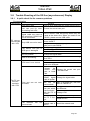
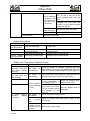
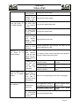
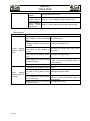
A quick check list for common problems................................................................................................ 59
3.9
Trouble-shooting instruction ......................................................................................63
3.9.1
3.9.2
3.9.3
System control data communication ...................................................................................................... 63
Display data communication .................................................................................................................. 64
Abnormal Display of the LED screen ..................................................................................................... 64
3.10
Recovery and maintenance.......................................................................................65
3.10.1
3.10.2
3.10.3
3.10.4
4
4.1
Replacement of power supply or other spare parts ............................................................................... 65
Replacement of the display module....................................................................................................... 66
Replacement of the control card ............................................................................................................ 66
Replacement of LDU3000 ..................................................................................................................... 67
Appendix: Instructions for the Function of the Main Control Board ..................... 68
Instructions for the control board QS5002L in the imposa ® cabinet ........................ 68
4.1.1
4.1.2
4.1.3
4.2
4.2.1
4.2.2
4.2.3
4.3
4.3.1
4.4
4.5
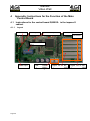
Layout .................................................................................................................................................... 68
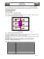
Instructions for the Interface Functions of the Control Board QS5002 ................................................... 69
SW1: Functional DIP Switch SW1: ........................................................................................................ 69
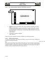
Instructions for the LDU3000 HUB Board QS5003 .................................................... 70
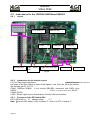
Layout .................................................................................................................................................... 70
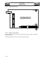
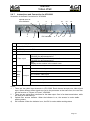
Instructions for the Interface ports ......................................................................................................... 70
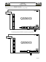
Functions of the DIP Switch SW1 .......................................................................................................... 70
Annexed Table: Technical Parameters of the Cabinet imposa®................................ 71
Annexed Graph: System Block Diagram ............................................................................................... 72
Items and Part Numbers ...........................................................................................73
Bolts Used in Imposa® box........................................................................................79
Outline
This manual consists of 3 parts:
Part 1: Design of the frame. Users can find the introductions about the cabinet, use of the
accessories, ways of installation, design of the main frame and the other issues that need attention.
Part 2: Connection of the display. This part tells the users how to install the cabinets, and
how to connect the signal and power wires and cables.
Part 3: Commissioning and Maintenance. In this part, users will be able to find out how to set
up, test and maintain the display. Daily maintenance tips are also given. They will also find
the explanations for the functions and usage of the control boards.
Page 4
Manual
Video Wall
1
1.1
Part 1 Design of the Frame
The cabinet and the display
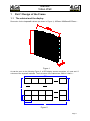
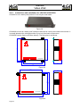
Dimension for the imposa® cabinet (as shown in Figure 1): 480mm X640mmX150mm :
Figure 1
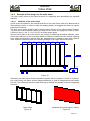
As can be seen in the following Figure 2, a LED display screen comprises “m” rows and “n”
columns of the imposa® cabinets. The front sizes of the cabinet are: 480*m X 640*n :
640*n
480
480*m
m
640
n
Figure 2
Page 5
Manual
Video Wall
In order to make the installation work much easier and more convenient, we strongly recommend the users assemble the cabinets according to the serial number that we had put on the
cabinets. As the following drawing shows, we have put the number label A(0,0) at the upper
right corner of the back cabinet. Other cabinets are numbered incrementally on the row and
column in the same way:
A(n-1,0)
A(3,0)
A(2,0)
A(1,0)
A(0,0)
A(n-1,0)
A(3,1)
A(2,1)
A(1,1)
A(0,1)
m
A(n-1,m-1)
A(3,m-1) A(2,m-1) A(1,m-1) A(0,m-1)
n
Rear View
Figure 3
1.2
1.2.1
Use of installation accessories
The connection bracket
To ensure the correct installed position, the 4 adjacent cabinets are fixed with a bracket, as
the following drawing shows.
Figure 4
Page 6
Manual
Video Wall
Drawing of the backboard:
Nut:2-
780-61001
Figure 5
1.2.2
The Bracket
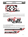
As shown in Figure 4, the bracket is used for fixing the installation plate to the pre-designed
column bar.
The bracket and installation plate are installed onto the square bar. When the screws are not
fastened, the bracket and the installation plate can slide in four directions. This is to allow
precise positioning of cabinets.
Drawing of the bracket:
780-61001
Figure 6
1.2.3
To install the positioning bar
Before installing any cabinet to the support structure, a positioning bar must be installed first
so as to guarantee the horizontal level of the screen. This positioning bar is installed at the
bottom of the support structure.
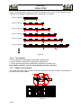
There are two types of positioning connecting bars: 1920mm long & 1280mm long. 1920mm
is for connecting 3 cabinets in a string, while 1280mm is for 2 cabinets in a string.
780-61003
780-61004
Figure 7
Page 7
Manual
Video Wall
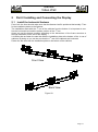
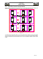
Users can choose either type of the bars according to the number of the cabinets and dimension of the display for positioning and connecting. For example :
2 rows of cabinets
1280
3 rows of cabinets
1920
4 rows of cabinets
1280
1280
The Connector
5 rows of cabinets
1920
1280
The Connector
6 rows of cabinets
1920
1920
The Connector
7 rows of cabinets
1920
1280
The Connector
1280
The Connector
Figure 8
1.2.4
The fastener
To fix the brackets: bolt M10X50, SpacerФ10, Washer Ф10
To fix the cabinet: bolt M10X25, SpacerФ10, Washer Ф10
To fix the positioning bracket: bolt M10X25, SpacerФ10, Washer Ф10
Note: Metric system is used for all the thread and size of the bolts.
1.2.5
Water proof seal pipe
The water proof seal pipe is used to seal the connection hole that is used as a passage for
the power and control cables.
seal
seal
780-62001
Figure 9
Page 8
Manual
Video Wall
1.2.6
Input cable seal pipe
Usually, the protecting input seal pipe is on the right side of the cabinet if you look from the
back side. When the screen is very wide and there are many cabinets in a row, such seal
pipes are found on both sides. These seal are used for protecting the power cords and the
input signal wires from the signal distributor LDU 3000.
seal
780-62002
Figure 10
1.2.7
Signal wires
(for the convenience of user installation, these cables are often packed inside the cabinets
when leaving the factory)
Signal connection between the cabinets.
R
B
RX+ R
RX- B
G
W
4X24AWG
RS+ G
RS- W
780-63101
Figure 11
Note: The signal wires from LDU3000A HUB to the 1st column cabinets are usually packed in
the HUB box.
1.2.8
Power cord.
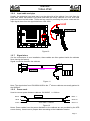
Used to connect power between cabinets: 3X12AWG, L=1500mm
Black L
780-63201
White N
Green G
Black L
White N
3X12 AWG L=1500mm
Green G
Figure 12
Notes: Power cables from the power distributor to the cabinets are not provided by the LED
screen factory. Users have to prepare them according to the installation location.
Page 9
Manual
Video Wall
1.3
1.3.1
Ways of installation
Single pole supporting
Single pole supporting is ideal for the open area, which is flexible in installation and neat in
appearance. This way of installation is less likely to be restricted by the location of installation
or by the size of the display.
Figure 13
1.3.2
Two poles supporting
Two poles supporting can be considered if the display is large. This way of installation is not
restricted by the location or the size, either. Usually, the display will be put together with other signs and have housing and border decorations.
Figure 14
Page 10
Manual
Video Wall
1.3.3
Installed on a platform
In such way of installation, the screen is seated on a platform on a building. Under this circumstance, users have to consider the weight of the sign, wind area and the loading rate of
the building.
Figure 15
1.3.4
Wall mounting
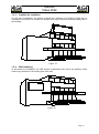
In this method of installation, the LED screen is attached to the wall of the building. Users
need to pay attention to the loading rate of the wall.
Figure 16
Page 11
Manual
Video Wall
1.4
1.4.1
Design of the main frame
Confirmation for the measurements of the display and size of the frame.
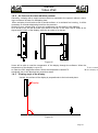
The dimensions of the display are determined by the resolution of the display or by the numbers of the modules (W XH). For the convenience of installation and housing or decorative
structure, the size of the frame is usually built larger than the dimensions of the display( (W +230) X (H+210mm)) , as the following drawing shows.
W+230
W(640*n)
640
640
640
480
480
H+210
H(480*m)
480
480
640
Figure 17
Page 12
640
640
640
640
Manual
Video Wall
1.4.2
Example of the design for the main frame:
The main frame refers to the frame structure for supporting and assembling the imposa®
cabinets.
1.4.2.1
Materials of the main frame
Under usual circumstance, the material and size of the main frame need to be determined at
the installing location. In order to make the welding easier, we suggest the client use square
pipes as the material.
The size of the vertical installing bar is determined by the size of the cabinet fixation bracket.
The size should be moderate, neither too large nor too small. We suggest the size of 45mm
X 45mm X 4mm (1 3/4” X 1 3/4” X0.16”) for these square pipes.
Since the front face of the main frame is the surface for attaching the display cabinets, users
should pay attention to the horizontal distance (640mm) between the two vertical installing
bars. Users should assure that the bars are perpendicular or parallel to each other. What is
more, attention should be paid to the welding strength of the upper and lower beams.
640
640
640
640
640
640
640
640
640
0.5 A
0.5 B
B
A
Full Weld
A
Figure 18
Generally, the main frame will be assembled together with the display in house or in the factory. After testing, the frame and the display attached to it, shall be transported to the installation site. Then the whole structure shall be hung up, seated and welded to the site supporting
structure.
Main frame
Figure 19
Assemble and commission in factory
Figure 20
Page 13
Manual
Video Wall
Hoisted at site
Figure 21
Overall effect
Figure 22
If the display is a large one, for example, using more than 10X6 imposa® cabinets, we suggest that a thicker main frame be used. Necessary reinforcement is also desirable. Consulting an architect for professional advice on structure strength and construction is very important. Otherwise, the screen may be deformed during or after hoisting and installation.
Figure 23
1.4.3
Figure 24
Decorating the borders
If there is any decorating border or housing around the display, the separation gap between
the cabinet and the wrapped border should be not less than 10mm.
If the user has no plan to build any decorating border for the display, we recommend that the
user take the frame that provided by the factory as the decorating boarder to cover the installation connecting bar.
Page 14
Manual
Video Wall
1.4.4
Air flow and the heat radiation problem
Generally, a display with a simple structure which is exposed to the open air without a housing or enclosure is better for dissipating heat.
When a display is built inside a wall or similar surface, or is enclosed in a housing , it will be
necessary to consider dissipating heat from the structure.
Shutter louvers, exhaust fans, or even air conditioners can be used for heat radiation.
As is known to all, the hot air flows from below to the top. In this case, the air intake is designed at the bottom of the display, while the air outlet is on the top.
Figure 25
Users will be able to read the temperature of the display through the software. When the
temperature of the display is up to 60
℃, the control
to under the 50% brightness status. When the temperature reaches 70
u℃, the display w
tomatically turn to the black screen protection status.
1.4.5
Viewing angle of the display
Usually, the surface of the display is perpendicular to the horizontal plane.
Display
¡
90
ã
Figure 26
Page 15
Manual
Video Wall
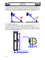
In order to guarantee the viewing effect, sometimes the display needs to be tilted towards the
front, especially under the following 2 circumstance: 1)When the location of the display is far
too high for the viewer, and the viewing angle is beyond 25°; 2) The viewing distance is restricted due to the limited space. Users need to create a viewing angle between the display
and the ground. A slanting angle installation can greatly increase the viewing effect.
Display
<25
¡ã
Display
¡
90
ã
Figure 27
1.4.6
Maintenance access
If the height of the display exceeds, for example, 5 stacks of cabinets (2400mm), we will
have to think of making a maintenance access to make the service job easier.
The maintenance access, with the width of over 600mm, should be designed exactly in the
middle of the two rows of the cabinets. To make the connection of the installation plate much
easier to fix, the distance between the maintenance platform and the installation plate should
be at least 100mm apart. See figure below :
W
H
Maintenance platform
(Designed between
two rows of cabinets)
100
The Maintenance access
should be over 600mm
Figure 28
Page 16
Manual
Video Wall
2
2.1
Part 2 Installing and Connecting the Display
Install the horizontal fastener
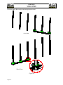
First of all, the client should make sure that the fastener itself is positioned horizontally. Then
fix the installation plates to the fastener.
The installation starts with the 1st row of the cabinets from the bottom. It is important to confirm the horizontal level and the bottom position of the 1st row.
Users can get the bottom position according to the dimensions of the frame structure or
through calculation of the size of the display.
It is better that we fasten the steel bar with the installation plate at the bottom of the 1st row of
cabinets. By doing so, we can be sure that the 1st row of the cabinets are horizontal.
Fasten the bar steel with the installation plate on the bottom of the cabinets
Front View
Back View
Figure 29
Page 17
Manual
Video Wall
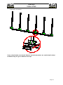
Fix to the frame. Be sure the connecting bars are level.
Front View
Back View
Figure 30
Page 18
Manual
Video Wall
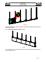
Connection of the bars
Figure 31
Users should make sure that all fastener and the connectors are vertical and horizontal before they can go on with the next step.
Page 19
Manual
Video Wall
2.2
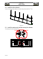
Install the 1st cabinet
The principle of installing the cabinets: from the bottom to the top. From left to right or from
the right to the left if the cabinets are in the same row.
As the following drawing shows, when installing, first of all, put the Am-n cabinet on the left
side of the frame. Make sure that it is horizontal and fix the two installation plates on the top.
Front View
Back View
Figure 32
Page 20
Manual
Video Wall
Figure 33
Users should make sure that the cabinet is vertical and horizontal before they can go
on with the next step.
2.3
Install the cabinets of the 1st row
Fig 34
Users should make sure that the cabinets are vertical and horizontal before they can
go on with the next step.
Page 21
Manual
Video Wall
2.4
Install the other cabinets
Users can install the other cabinets in the same way as they install the 1st row.
Figure 35
2.5
Install the water-proof seal pipe among the cabinets
The drawing of the seal is shown below :
seal
seal
Figure 36
Page 22
Manual
Video Wall
2.6
Connect the Signal Cables
2.6.1
Signal wiring block diagram
A(1,0)
J1
J3
J4
J2
LDU3000A HUB BOX
P1
SW1
SW1
JP7
A(1,m-1)
CON3
CON3
CON2
TX+ R
TX- B
RS+ G
RS- Y
D-
D+
RXD1
SEL
RS-
RS232
RS485
RS+
TXD1
COM1
MODE
GND
OPEN
COM1
GND
CL
CON9
RXD2
CH
CON8
COM2
TXD2
CON1
Pn
JP4
SW1
JP2
5002
JP12
JP7
CON3
CON3
CON2
CON2
TX+ R
TX- B
RS+ G
RS- Y
TX+ R
TX- B
RS+ G
RS- Y
SEL
DC 5V
CON2
JP7
CON3
TABLE OF SEL
CON7
SENSOR
LUM SENSOR
J1
J2
J3
J4
J5
JP4
JP2
5002
SW1
GND
CON2
JP7
CON2
J6
J1
J2
J3
J4
J5
J6
JP12
JP2
SW1
JP12
5002
JP4
J2
J3
J4
J5
J6
J1
GND
CON2
CON3
A(0,m-1)
QS5003
LINK
TX+ R
TX- B
RS+ G
RS- Y
A(n-1,m-1)
GND
P2
CON2
TX+ R
TX- B
RS+ G
RS- Y
TX+ R
TX- B
RS+ G
RS- Y
P1
P2
GND
CON2
CON2
TX+ R
TX- B
RS+ G
RS- Y
CON3
P1 P2 P3 P4 P5 P6 P7 P8 P9 P10 P11 P12 P13 P14 P15 P16
CON2
CON3
ACT
CON5
CON3
VCC
VCC
LUM
LUM
CON3
+5V
JP7
CON2
CON3
GND
GND
CON2
JP7
JP2
5002
JP4
J1
J2
J3
J4
J6
SW1
JP12
JP2
5002
JP4
J5
A(0,1)
J1
J2
J3
J4
J5
J6
JP12
SW1
GND
CON2
CON3
JP2
TX+ R
TX- B
RS+ G
RS- Y
JP4
JP2
5002
CON2
A(1,1)
J1
J2
J3
J4
JP4
CON3
TX+ R
TX- B
RS+ G
RS- Y
TX+ R
TX- B
RS+ G
RS- Y
A(n-1,0)
GND
CON3
CON2
CON2
JP7
CON2
JP7
JP7
CON3
CON3
TX+ R
TX- B
RS+ G
RS- Y
J5
SW1
GND
CON2
CON3
CON2
J6
5002
JP1 2
SW1
GND
CON2
CON3
JP12
J5
J6
J1
J3
J4
J2
JP2
5002
JP1 2
GND
A(0,0)
JP4
J5
J6
J1
J3
J4
J2
JP2
SW1
JP1 2
5002
JP4
J5
J6
A(n-1,0)
TX+ R
TX- B
RS+ G
RS- Y
Rear View
Fiber optic
5
INPUT
OUTPUT
TXD RXD
GND
CVBS 1 CVBS 2
3 2
DVI
DVI
VGA
Pb
S_VIDEO
RS232
Enthernet
VPU 3000
PC
PC
DVI
AC INPUT
84~260V
RS232
RS232
Pr
Y
CVBS 4 CVBS 3
USB
DVI OUT DVI IN
Video
VGA IN
USB
S-Video
OFFLINE
VGA Synchronous
Fig .37
Page 23
Manual
Video Wall
2.6.2
Instructions and Installation for LDU3000 /LDU3000A
LDU3000 is not a water-proof product. It can only be used indoor.
Figure 38
450
496
LDU3000A is built as a water proof instrument and can be used in the outside environment. It
is usually placed at the mid-right position if you look from back of the screen.
LDU3000A can be fixed to the frame directly. The fixing size is as follows:
34
LDU3000A
290
128
350
Figure 39
350
LDU3000A
396
Figure 40
Page 24
42
450
390
128
Manual
Video Wall
2.6.3
Signal Wire Connection among Cabinets
CON3
J1
JP2
SW1
JP7
J1
JP4
JP2
SW1
JP4
SW1
JP12
GND
CON3
CON2
CON3
JP7
CON2
CON3
JP7
CON2
CON2
CON3
JP2
5002
JP4
SW1
JP12
JP2
5002
JP4
JP2
GND
J1
J2
J3
J4
J6
J5
A(0,m-1)
J1
J2
J3
J4
J6
J5
A(1,m-1)
A(n-1,m-1)
SW1
TX+ R
TX- B
RS+ G
RS- Y
CON3
TX+ R
TX- B
RS+ G
RS- Y
JP7
CON2
JP7
JP7
CON2
CON3
CON2
TX+ R
TX- B
RS+ G
RS- Y
CON2
CON3
J2
J3
JP4
J4
J5
5002
JP12
SW1
CON3
CON2
J1
5002
GND
J2
J3
J4
J5
JP4
JP2
5002
JP12
JP7
CON3
TX+ R
TX- B
RS+ G
RS- Y
J2
GND
CON2
CON3
CON2
J3
J6
J1
J2
J3
J4
J5
J6
JP4
SW1
GND
CON2
J4
A(0,1)
A(1,1)
A(n-1,0)
CON3
J5
5002
JP12
TX+ R
TX- B
RS+ G
RS- Y
TX+ R
TX- B
RS+ G
RS- Y
JP2
5002
JP12
GND
CON3
CON3
CON2
CON2
J1
J2
J3
J4
J5
CON2
JP7
JP7
CON3
TX+ R
TX- B
RS+ G
RS- Y
J6
GND
CON2
CON3
CON2
JP12
J6
J1
J2
J3
J4
GND
CON2
CON3
J6
JP2
5002
SW1
SW1
JP12
JP2
5002
JP12
GND
A(0,0)
JP4
J5
J6
J1
J2
J3
A(1,0)
A(n-1,0)
JP4
J4
J5
J6
Signal wires are transmitted in the direction of row. Viewed from the back of the display, the
signal wire begins with the first cabinet in the right, and concatenated to the left.
CON3
TX+ R
TX- B
RS+ G
RS- Y
TX+ R
TX- B
RS+ G
RS- Y
Rear View
Figure 41
To make the wire-connection easier, we can start with the first cabinet in the left. The signal
wire is of 4P single head. Users are required to lead it from the control board QS5002 CON3,
cross the water-proof cannula and then insert it onto the adjacent cabinet‘s control board
CON2.
Page 25
Manual
Video Wall
LDU3000/LDU3000A-Display Connection
J3
J4
JP4
J5
J6
J2
JP 2
SW1
JP1 2
GND
GND
CON2
JP7
JP7
CON2
CON3
CON3
CON2
CON2
1
TX+ R
TX- B
RS+ G
RS- Y
1
TX+ R
TX- B
RS+ G
RS- Y
JP4
J2
J1
J3
J4
J5
J6
LDU3000A HUB Box
P1
SW1
CON2
SW1
JP7
QS5003
TABLE OF SEL
SEL
CON9
D-
D+
RXD1
COM1
MODE
GND
RS232
OPEN
RS485
COM1
RS+
CL
CH
CON8
COM2
TXD1
CON1
SENSOR
DC 5V
LINK
CON7
LUM SENSOR
GND
P1
P2
RXD2
TX+ R
TX- B
RS+ G
RS- Y
TXD2
P2
2
CON2
2
TX+ R
TX- B
RS+ G
RS- Y
P1 P2 P3 P4 P5 P6 P7 P8 P9 P10 P11 P12 P13 P14 P15 P16
CON3
CON2
GND
CON5
CON3
ACT
JP7
CON3
RS-
GND
CON2
CON3
GND
JP1 2
GND
JP 2
5002
JP 2
SW1
JP1 2
5002
JP4
J2
A(0,1)
J1
J3
J4
J5
J6
A(0,1)
SEL
CON3
CON3
VCC
VCC
LUM
LUM
J3
J4
J5
J1
5002
JP 2
SW1
JP1 2
5002
JP4
J6
J2
A(0,0)
J1
A(0,0)
+5V
2.6.4
Pn
JP4
J2
J1
J3
J4
J5
J6
SW1
JP1 2
GND
CON3
CON2
JP7
CON2
CON3
JP7
GND
JP 2
5002
JP 2
SW1
JP1 2
5002
JP4
J2
A(0,m-1)
J1
J3
J4
J5
J6
A(0,m-1)
CON3
CON3
n
CON2
TX+ R
TX- B
RS+ G
RS- Y
CON2
TX+ R
TX- B
RS+ G
RS- Y
1
2
1
n
AC INPUT
84~260V
SENSOR
ETHERNET
RS485
D- D+
1
3
5
7
9
11
13
15
2
4
6
8
10
12
14
16
CHANNEL
TX
RX
LDU3000 HUB Box
2
Rear View
Rear View
Figure 42
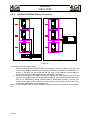
As can be seen in the above figure:
1. When connecting the LDU3000 HUB to the display, the right cabinet in the first row
on top of the display (viewed from the back) should be connected with LDU3000’s. Interface 1. Similarly, we can conclude that the input of the cabinet’s control board in
the second row should be connected with LDU3000’s interface 2.
2. When connecting the LDU3000A HUB to the display, the right cabinet in the first row
on top of the display(viewed from the back) should be connected with the output interface P1 of QS5003,the interior control board of LDU3000A. Similarly, we can conclude that the input of the cabinet’s control board in the second row should be connected with QS5003A’s output interface P2…
Note: For the detailed instructions of QS5003, please consult the instructions in the appendix.
Page 26
Manual
Video Wall
2.6.5
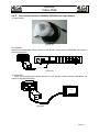
Connection between LUD3000/LDU3000A and Light Sensor
1) Light Sensor
Figure .43
2) LUD3000
Insert the provided light sensor directly to the Sensor socket behind LDU3000. As shown in
the following figure.
2
CHANNEL CHANNEL
1
TX RX TX RX
CH1
CH2
Figure.44
3) LUD3000A
Insert the provided light sensor directly to the Sensor socket behind LDU3000A. As
shown in the following figure.
LDU3000A HUB Box
SW1
CON5
TABLE OF SEL
SEL
COM1
MODE
GND
RS232
OPEN
RS485
D-
D+
RXD1
TXD1
RS-
SEL
RS+
GND
COM1
RXD2
CL
CON9
GND
CH
CON8
COM2
LINK
GND
ACT
VCC
VCC
LUM
LUM
CON1
SENSOR
DC 5V
TXD2
CON7
LUM SENSOR
+5V
P1 P2 P3 P4 P5 P6 P7 P8 P9 P10 P11 P12 P13 P14 P15 P16
QS5003
Figure 45
Page 27
Manual
Video Wall
2.6.6
The communication between LDU3000/A and the PC
SW1
CON5
TABLE OF SEL
SEL COM1
MODE
GND RS232
RS-
RS+
RXD1
OPEN RS485
SEL
GND
D-
TXD1
D+
CON9
COM1
RXD2
GND
LINK
CL
GND
ACT
CH
DC 5V
+5V
SENSOR
LUM SENSOR
CON8
COM2
TXD2
CON1
CON7
VCC
VCC
LUM
LUM
P1 P2 P3 P4 P5 P6 P7 P8 P9 P10 P11 P12 P13 P14 P15 P16
QS5003
•
LDU3000/A' mainboard-QS5003.There are two separate COM ports in the mainboard
COM1: RS232&RS485; If a user chooses SEL for communicating (SEL connects
to GND), the user choose RS232 communication; If SEL is not chosen, then the
user use RS 485 for communication. Communication RS232/RS485 can't be used
at the same time
COM2: RS232
•
LDU3000/A's mainboard -QS5003
CON1: Ethernet
Please refer to more detailed information of QS5003 in the following charpters.
2.6.6.1
RS232 communication
1) Under the offline system, users should use RS232 to communicate with teh LDU3000/A to
change the message and setting.
2
)Under
rthe VG A
sion.
Note: Please pay attention to the RS232 wiring when you communicating or programming,
no matter the sign is under offline system or VGA system. Due to the limit communicating
distance of RS232, we suggest the users lead the RS232 wire from the button of the sign. In
this case, users can easily connect the PC to the com port.
Page 28
Manual
Video Wall
3
) RS232 connection
This drawing shows the RS232 connection by using COM 1 :
SW1
CON5
P1 P2 P3 P4 P5 P6 P7 P8 P9 P10 P11 P12 P13 P14 P15 P16
QS5003
TABLE OF SEL
SEL COM1
MODE
GND RS232
RS-
RS+
RXD1
SEL
GND
TXD1
D-
OPEN RS485
TXD1
GND
RXD1
D+
GND
CON9
COM1
RXD2
LINK
ACT
CL
GND
CH
VCC
VCC
LUM
LUM
DC 5V
+5V
SENSOR
TXD2
CON1
CON7
LUM SENSOR
CON8
COM2
This drawing shows the RS232 connection by using COM 2 :
SW1
CON5
TABLE OF SEL
SEL COM1
MODE
GND RS232
RS-
RS+
SEL
OPEN RS485
RXD1
GND
TXD1
D-
D+
CON9
COM1
RXD2
GND
LINK
TXD2
ACT
GND
CL
CH
DC 5V
+5V
SENSOR
LUM SENSOR
CON8
COM2
TXD2
GND
RXD2
CON1
CON7
VCC
VCC
LUM
LUM
P1 P2 P3 P4 P5 P6 P7 P8 P9 P10 P11 P12 P13 P14 P15 P16
QS5003
Page 29
Manual
Video Wall
2.6.6.2
RS485 Communication
SW1
CON5
TABLE OF SEL
SEL COM1
MODE
GND RS232
RS-
RS+
RS+
RS-
RXD1
OPEN RS485
SEL
GND
D-
TXD1
D+
CON9
COM1
RXD2
GND
LINK
ACT
CL
GND
CH
DC 5V
+5V
SENSOR
CON8
COM2
TXD2
CON1
CON7
LUM SENSOR
VCC
VCC
LUM
LUM
P1 P2 P3 P4 P5 P6 P7 P8 P9 P10 P11 P12 P13 P14 P15 P16
QS5003
2.6.6.3
Ethernet Communication
Under the off line system, users can connect the Ethernet wire to the CON1 in mainboard
5003 of LDU300/A.
The Following Signal Connection is for VGA Synchronous System
Page 30
Manual
Video Wall
2.6.7
Instructions and Connection for VPU3000
Illustration of the Back Connection for VPU3000
Optical fiber access indicator
5
2
1
6
DVI indicator
3
4
1
Power supply input: AC110V/220V
2
Ventilation fan outlet
3
RS232 port to the PC
4
USB port to the PC
5
6
Data output
7
8
Passage 1
9
10
8
9
11
12
14
13
“CHANNEL1”: Optical fiber output port. It is connected to
LDU3000 for data transmission.
“CHANNEL 2”: Optical fiber output interface. It is connected to
LDU3000 for data transmission.
“DVI”
display as the monitor in the control room.
“DVI”: DVI video input
“VGA”: VGA video input
10
Video
11
data
12
7
input
“Y”/“CVBS4” video input
“Pr”/“CVBS3” video input
Passage 2
“Pb ”/“CVBS2” video input
13
“CVBS1” video input
14
“S-Video” video input
Notes:
1 ) There are two video input channels in VPU 3000. Each channel accepts one video signal
input. When different video signals are fed to the processor at the same time, the user can
get the function of “Picture In Picture” VPU3000.
2 ) There are two optical fiber interfaces for the data output. One is for data transmission, while
the other is for hot back-up.
3)
Optical fiber access indicator: When the indicator is on, the access is under stable
working status
4)
DVI indicator: When the indicator is on, the DVI is under stable working status
Page 31
Manual
Video Wall
2.6.7.1
Optic Fiber Connection between VPU3000 and LDU3000
For the data output, there are two optic fiber interfaces. One is for data sending, and the other is for hot backup.
LDU 3000
AC INPUT
84~260V
SENSOR
ETHERNET
RS485
D- D+
1
3
5
7
9
11
13
15
2
4
6
8
10
12
14
16
CHANNEL
TX
RX
Fiber optic
VPU 3000
5
INPUT
OUTPUT
TXD RXD
GND
CVBS 1 CVBS 2
3 2
DVI
VGA
DVI
Pb
S_VIDEO
DVI
AC INPUT
84~260V
RS232
Pr
Y
CVBS 4 CVBS 3
USB
Figure 47
2.6.7.2
Connection between VPU3000 and PC DVI
VPU 3000
PC
5
INPUT
OUTPUT
TXD RXD
GND
CVBS 1 CVBS 2
3 2
DVI
VGA
DVI
Pb
S_VIDEO
DVI
AC INPUT
84~260V
RS232
Pr
Y
CVBS 4 CVBS 3
USB
DVI
DVI
Figure 48
2.6.7.3
USB:
Connection between VPU3000 and PC COM
VPU 3000
PC
5
INPUT
OUTPUT
TXD RXD
GND
CVBS 1 CVBS 2
3 2
DVI
DVI
VGA
Pb
DVI
AC INPUT
84~260V
RS232
USB
Figure 49
Page 32
USB
Pr
Y
CVBS 4 CVBS 3
S_VIDEO
Manual
Video Wall
RS232:
VPU 3000
PC
5
INPUT
OUTPUT
TXD RXD
GND
CVBS 1 CVBS 2
3 2
DVI
VGA
DVI
Pb
S_VIDEO
DVI
AC INPUT
84~260V
RS232
Pr
Y
CVBS 4 CVBS 3
USB
RS232
Figure 50
2.6.7.4
Connection between VPU3000 and Video Sources
For VPU3000, there are two video input channels, each of which has one video signal input.
When the two video signals are input at the same time, the function of picture in picture can
be realized.
5
INPUT
OUTPUT
TXD RXD
GND
CVBS 1 CVBS 2
3 2
DVI
DVI
VGA
Pb
S_VIDEO
DVI
AC INPUT
84~260V
RS232
USB
PC
Pr
Y
CVBS 4 CVBS 3
S-Video
VGA IN
DVD
Video
Figure 51
Page 33
Manual
Video Wall
2.7
2.7.1
Connection of Power Cords
General Block Diagram of Power Cable Connections
POWER IN
POWER INPUT
L N G
POWER INPUT
POWER INPUT
L N G
A(n-1,0)
A(n-2,0)
POWER INPUT
L N G
L N G
A(1,0)
A(0,0)
AC Input
3 phases 5 lines
POWER IN
POWER INPUT
L N G
POWER INPUT
POWER INPUT
L N G
A(n-1,1)
A(n-2,1)
Power
Distribution Box
POWER INPUT
L N G
L N G
A(1,1)
A(0,1)
POWER IN
POWER INPUT
L N G
A(n-1,m-1)
POWER INPUT
POWER INPUT
L N G
L N G
A(1,m-1)
A(n-2,m-2)
POWER INPUT
L N G
A(0,m-1)
Rear View
Figure 52
The above graph is sighted from the back of the display.
Cables from AC input to the distribution box should be prepared by the customers, and the
grounding should be guaranteed. The resistance should be less than 4Ω.
The diameter of the cables is determined by the distribution box’s power rating. It must meet
the maximum power rating.
2.7.2
Installation and Principle of Distribution Box
Generally speaking, the distribution box is fixed at the central of the display’s right side
(viewed from the back) so as to make the arrangement of wires and maintenance more convenient.
We can choose distribution boxes with different specifications according to the power rating
of the display. Depending on the maximum output of it, the distribution box has two specifications: 25KW and 40KW. Usually, the input of the distribution box is three phase five lines.
Page 34
Manual
Video Wall
Principle Chart of the 25KW Distribution Box:
GND
N
L1 L2 L3
POWER IN
KO
LDU3000A
PSU-25
C1 PL N G
C1 PL N G
SPD
K1
Lm1
KM1
KT1
KT2
KM2
KM3
K4
K3
K5
C1
Remote
Jout PL N G PF N G 1 N G 2 N G 3 N G 4 N G 5 N G 6 N G 7 N G 8 N G 9 N G
POWER
PL(LUD300A)
OUTPUT
PF
1
2
4
3
5
6
7
8
9
Figure 53
Instructions:
POWER IN
POWER OUTPUT: power output
PL: power for LDU3000A
PF: power for exhaust fan
1~9: power for the modules of the cabinet
:power input, 25KW , 3 phases 5 lines
;illum
powerination;
output Maxim
1KW; um
;Maxim um power output 1KW ;
;Maxim um power f
Technical Parameters’ of the Distribution Box (25KW)
Total input power
25KW
3 phases 5 lines
Maximum input cur-
38A
AC220V
rent for each phase
76A
AC110V
Maximum outputs of
9 outputs
distribution box
Maximum power for
2.5KW
each output
Maximum current for
each output
12A
AC220V
24A
AC110V
Page 35
Manual
Video Wall
Principle Chart of the 40KW Distribution Box:
GND
N
L1 L2 L3
POWER IN
KO
K0
Main Switch
3Phases 80A
SPD
SPD
OBO 3Ph
KM1,2,3
Contactor
X5 TE 2510 110V
KT1,2
Timer
X4 30 S
Jc
Remote & Next Con
X2 UK5N
Lm1
Lamp
X1 110V Green
K1,
Switch
X1 NO Turning
JOUT
OUTPUT
X52 UK6N
SPD
K1
Lm1
KM1
KT1
KM2
K4
K3
C1
KT2
KM4
KT3
KM3
K5
KT4
KM5
K7
K6
C2
Remote Next Con.
Jout PL N G PF N G 1 N G 2 N G 3 N G 4 N G 5 N G 6 N G 7 N G 8 N G 9 N G 4 N G 5 N G 6 N G 7 N G 8 N G 9 N G
POWER
PL(LUD300A) PF
OUTPUT
LDU3000A
C1 PL N G
1
2
3
4
5
6
7
8
9
10
11
12
13
14
15
PSU-40
C1 C2 PL N G
Figure 54
Instructions:
POWER IN
:power input, 40KW , 3 phases 5 lines
POWER OUTPUT: power output
PL: power for LDU3000A
;illum ination; Maxim um power o
PF: power for exhaust fan
;Maxim um power output 1KW ;
1~9: power for the modules of the cabinet
;Maxim
put
2.5KW
um power for each ou
Technical Parameter of the Distribution Box(40KW)
Total input power
40KW
3 phases 5 lines
Maximum input current for each
60A
AC220V
120A
AC110V
phase
Maximum outputs of distribution box
15
Maximum power for each output
2.5KW
Maximum current for each output
12A
AC220V
24A
AC110V
Power rating for each output of the distribution box is 2.5KW.
Page 36
Manual
Video Wall
“N” imposa® cabinets can be connected to the distribution box. As the following table shows:
Table 2
pitch
parameter
10mm
13.3mm
16mm
17.7mm
20mm
26.7mm
32mm
40mm
pixels on each standard
cabinet
48X64
36X48
30X40
27X36
24X32
18X24
15X20
12X16
Maximum power per
cabinet
360W
500W
430W
360W
290W
160W
150W
150W
Number of driven cabinets for each output
5
4
5
5
8
12
12
12
45
36
45
45
72
108
108
108
75
60
75
75
120
180
180
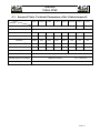
180
Number of driven cabinets of 25KW distribution
box
Number .of driven cabinets of 40KW distribution
box
2.7.3
Connection of Cabinets
Connection of the power cables of the cabinet are transmitted in the direction of row. Generally speaking, if viewed from the back of the display, the power cables begin with the last
cabinet (in the left) in each line, and concatenated to the right. If the total power of each row’s
cabinet is too large as to exceed the endurance of the power cable, the way of connecting
from both sides of each row to the midst can be tried. When connecting, just put the power
cable across the water-proof cannula and join the L N G separately. That is OK.
POWER IN
POWER INPUT
POWER INPUT
POWER INPUT
L N G
L N G
A(n-1,0)
A(n-2,0)
POWER INPUT
L N G
L N G
A(1,0)
A(0,0)
POWER IN
POWER INPUT
POWER INPUT
POWER INPUT
L N G
L N G
A(n-1,1)
A(n-2,1)
POWER INPUT
L N G
L N G
A(1,1)
A(0,1)
POWER IN
POWER INPUT
L N G
A(n-1,m-1)
POWER INPUT
POWER INPUT
L N G
L N G
A(1,m-1)
A(n-2,m-2)
POWER INPUT
L N G
A(0,m-1)
Rear View
Figure 55
Page 37
Manual
Video Wall
Due to the different pitches of each cabinet, the power consumption of each cabinet is different accordingly. For the number of allowed concatenated cabinet please consult the number
of driven cabinets for each output of the distribution box.
If the number of cabinet in row is more than that of the above mentioned, then one should
lead the wires from both sides of the cabinet and cascade them toward the midst.
POWER IN
POWER IN
POWER INPUT
L N G
POWER INPUT
POWER INPUT
L N G
A(n-1,0)
A(n-2,0)
POWER INPUT
L N G
L N G
A(1,0)
A(0,0)
POWER IN
POWER IN
POWER INPUT
L N G
POWER INPUT
POWER INPUT
L N G
A(n-1,1)
A(n-2,1)
POWER INPUT
L N G
L N G
A(1,1)
A(0,1)
POWER IN
POWER IN
POWER INPUT
L N G
A(n-1,m-1)
POWER INPUT
POWER INPUT
L N G
L N G
A(1,m-1)
A(n-2,m-2)
POWER INPUT
L N G
A(0,m-1)
Rear View
Figure 56
If the power consumption of a full color display exceeds 40KW, we suggest the user connect
the power distributors in series. That is, when a user turns on a full color display, the 1st distributor will be turned on first, then the 2nd one, the 3rd... The way of connection is explained below:
1) Lead a wire out from the C2 cable connector in Distributor 1;
2) Connect the wire to the C1 wire connector in Distributor 2, as shown in the following
drawing.
Page 38
LDU3000A
PSU-40(1)
PSU-40(2)
C1 PL N G
C1 C2 PL N G
C1 C2 PL N G
Manual
Video Wall
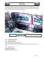
When we are leading the power supply cables from one cabinet to another, we must make
sure that the cables do not block the closure of the cabinets. The cables should be led from
the air intake hood in the bottom part of the cabinets. It is better to sheaf the cable with the
binding-wire in the middle, as the following photo shows.
Power cable
2.8
2.8.1
Air intake hood
The cable should be led from the bottom, and sheaved with the binding wire.
Connection Check
Electrical Check
Check if there is short circuit among L N G.
Check if there is open circuit among all wires.
Check if the maixmum current of the cascaded power cables exceeds the endurance of the
cable.
2.8.2
Signal Check
Communication connection
Video sources connection
Signal wire connection of cabinets
Page 39
Manual
Video Wall
3
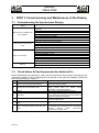
PART 3 Commissioning and Maintenance of the Display
3.1
Commissioning the Synchronous Display
Check
Status
Before power is applied to all
the equipment
Start up the computer and
VPU
Switch on the screen
Back up
Connections of power supply for the screen, LDU, VPU and video sources
equipment
Signal sources connected to VPU
Monitor
Optic fiber
Wire connections among cabinets
Wire connections between LDU and cabinets
Wire connections between VPU and computer
If VPU and video sources are electrified
Communications between computer and VPU
Seek effective video sources
Switch to different video sources and examine the display effect from monitor
If the cabinets and LDU are electrified
Communicaitons between computer and LDU
Read the parameters of LDU
Find all the cabinets
Basic test
Check the screen’s displaying effect
Adjust abnormal modules or cabinets
From LDU to computer
From VPU to computer
TABLE 1.1 Procedures for the commissioning of the display
3.2
Check before All the Equipments Are Switched On
Before powering all the equipment, users should connect the whole system according to the
instruction manual so as to guarantee the correctness of the system’s hardware. Please do
the check according to Table 1.2
Items
Connections of power supply for the
screen, LDU, VPU and video sources
Note
Check if there is short circuit among L N G and
1
open circuit among all wires
DVI, CVBS, S-Video, YPrPb, VGA. For details
2
Signal sources connected to VPU
please consult Table 1.3. Please check
acccotding to the required signals
3
Monitor
When VPU is attached with a DVI monitor
There is a pair of optic fiber inputs for LDU. Check
4
Optic fiber
if there is damage to the joints and if the joints are
inserted into the socket correctly.
The same with item 1, please pay attention to the
5
Wire connections among cabinets
direction of signal wires
Wire connections between LDU and cabi- Please connect according to the instruction man6
nets
ual
If USB and RS232 are connected between VPU
Wire connections between VPU and com- and computer at the same time, then only USB is
7
effective.
RS232
needs
one-to-oneputer
correspondence signal wires
TABLE 1.2 Check before all the equipments are electrified
Page 40
Manual
Video Wall
Item
Connect to
DVI output of computer
DVI
DVI input of monitor
VGA
VGA output of computer
CVBS
CVBS output of video sources
S-Video output of computer or video
S-Video
sources
YPrPb
Y, Pr, Pb output of video sources
TABLE 1.3 Video sources connected to VPU
3.3
•
Input
Input
Start up Computer and VPU
3.3.1
•
I/O
Input
Output
Input
Input
Check if VPU and video source equipment are switched on.
Consult the related instruction manuals to check if the video source equipment are
working
After being switched, the light of VPU’s power switch will be illuminated and there will
be contents shown on LCD. When the”+” or”-” on the panel is pressed, the background
light of LCD will shine.
3.3.2
Check communication between computer and VPU 2.2
VPU3000 control software is required. For details please consult User's Manual for VPU3000
Control Software,4.2 Start-up and Communication Settings.
3.3.2.1
Start up VPU3000 control software
3.3.2.2
Set communication parameters
VPU3000 control software will read VPU’s configuration automatically and enter the software
interface successfully, as long as there is no clues for mistake. The software interface is as
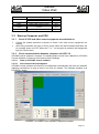
FIGURE2.1 shows.
FIGURE2.1 VPU3000 control software’s operation interface
Page 41
Manual
Video Wall
3.3.3
Search for valid video sources
VPU3000 control software is required. For details please consult User's Manual for VPU3000
Control Software,6.2.1 Search Signal.
• Click the “Search Signal” button in advanced setting to switch to the signal search interface.
•
Click “Start” button to search video signal. The LED sign will flash when searching video signal. After searching, you will find a window Figure2.2. The valid video sources
are S-video, CVBS3 and DVI.
Figure2.2 Search Signal input result interface,
3.3.4
Switch to different video sources and examine the display effect from
monitor
VPU3000 control software is required. For details please consult User's Manual for VPU3000
Control Software, 6.1.2 Select the Video Source and Display Mode.
• Choose DVI only in display mode, check the display
• Choose AV only in display mode, and click the button in Video Source Bar, and check
each valid video source.
Please play some programs in the video source before
checking the display.
Page 42
Manual
Video Wall
3.4
Power up the Screen
3.4.1
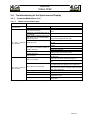
Check if the cabinets and LDU are powered up, see TABLE 3.1
Item
Check
Cabinets
are electrified
If the red and green LED indicators (STATUS and RUN) at the back
of the cabinets are twinkling
If the indicators of the switch inside the cabinets are lighted
If the red indicators beside optic fiber port at the back of VPU is
LDU is electri- lighted
fied
If the green indicator in the exterior of LDU is lighted
If the indictor light for switch power supply in LDU is lightened
TABLE 3.1 Check if the cabinets and LDU are powered
3.4.2
Check communication between computer and LDU
Imposa Tools software is required. For details please consult User's Manual for Advanced
Setting Up Software of Standard Cabinet, 6.1 Managing LDU, 6.5, Setting up LDU parameters.
• Run Imposa Tools software.
• Add a new LDU in LDU manager bar, via the COM port for VPU (USB or RS232).
• Press “Read back” button in the LDU setting window, and the value in the window will be
refreshed.
3.4.3
Read back the parameters of LDU
Imposa Tools software is required. For details please consult User's Manual for Advanced
Setting Up Software of Standard Cabinet, 6.6 Setting up the display’s parameters.
• Choose View\Screen setting or press “Screen Setting” button to view the Screen Setting
window.
• The software will read back the parameter of the sign automatically, then press “Read
back” button to refresh the window again.
• Check if the value in the window is set according to the sign.
3.4.4
3.4 Find all the cabinets
Imposa Tools software is required. For details please consult User's Manual for Advanced
Setting Up Software of Standard Cabinet, 6.7 Basic information of LDU, Adjusting of Basic
Color and Testing for Displaying.
• Choose View\View\Tile Information or press “View\Tile Information” button to view the
View\Tile Information window
•
Press the
button to refresh the tile information, and count the number of the green
cell after refreshing back.
3.4.5
Basic test
Imposa Tools software is required. For details please consult User's Manual for Advanced
Setting Up Software of Standard Cabinet, 6.7.4 Basic test. Select all of the tiles, and do the
Row scan and the Column scan test.
3.4.6
Check the screen’s displaying
Imposa Tools software is required. For details please consult User's Manual for Advanced
Setting Up Software of Standard Cabinet, 6.7.4 Basic test.
Stop the basic test, and play some pictures on the sign to see if there is abnormal displaying.
If in need, please operate as Figure 3.7 shows.
Page 43
Manual
Video Wall
3.4.7
Adjusting abnormal modules or cabinets
Imposa Tools software is required. For details please consult User's Manual for Advanced
Setting Up Software of Standard Cabinet, 6.7.3, Adjusting of Basic Color
to adjust
• Keep playing the screen. In the layout viewing window, select
basic colors.
• Select the mode of synchronous display and choose the cabinets to be adjusted.
• Move the slide bar or adjust the value in the input bar to produce an ideal displaying effect..
• Save the setting and send it to LDU.
• Check and see if the display after automatically recovering is satisfactory.
3.5
3.5.1
Back up
From LDU to computer
Imposa Tools software is required. For details please consult User's Manual for Advanced
Setting Up Software of Standard Cabinet, 7.1.1.2 Save to Computer.
•
Select Tool\Backup LDU date\Save to Computer.
•
Determine the location of back up files and name them.
•
Press” Backup” button to start the back-up and wait until it is finished.
3.5.2
From VPU to computer
VPU3000 control software is required. For details please consult User's Manual for VPU3000
Control Software, 6.1.4.2 Save Parameter Settings to a File.
•
Start up VPU3000 control software.
•
Click the menu: File / File Settings to a File.
•
Name the file and save the file to the PC.
•
Click “Save” button to finish saving setting file.
Page 44
Manual
Video Wall
3.6
Troubleshooting of the Synchronous Display
3.6.1
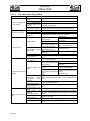
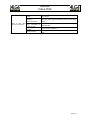
Common Malfunctions List
3.6.1.1
When communication part
Phenomena
PC cann’t communicate with LDU
Solution
PC cann’t communicate with VPU
VPU cann’t communicate with LDU
VPU hasn’t be started
Serial port connected with VPU is
not selected.
When USB and RS232 are used at
the same time for communication,
RS232 can’t work.
PC cann’t communicate with VPU
USB can’t work.
The port of computer’s RS232 or
USB is damaged.
Start up VPU, and check the power supply for
VPU.
Select the correct serial port.
It is normal. USB has priority over RS232. When
using RS232 please remove USB.
The driving program of USB isn’t set up, so set it
up first.
USB port is damaged. Choose another port or use
RS232.
Choose another port.
Select USB or RS232.
Repair the computer.
Communication wires of RS232 or
USB is damaged.
Change other communication wires.
VPU is broken.
Change another VPU,and input the saved files to
the new one.
Start LDU, and check the power supply of it.
LDU is not started
Optic fiber isn’t inserted well.
VPU cann’t communicate with LDU
Optic fiber joint is broken.
Optic fiber is broken.
The mother board of LDU is broken.
VPU is damaged.
LDU’s switch power supply is broken. Use a new
one.
Insert the optic fiber tightly and make sure that the
red light beside the optic fiber joint is lightened.
Optic fiber A1 and B1 are reverse. Transfer them
and make sure that the red light beside the optic
fiber joint is lightened.
Change the joint.
Change optic fiber.
Change QS5003D,and resend the back-up files in
computer to LDU.
Change VPU, and input the saved configuration
files to VPU.
TABLE 4.1 Cumming malfunctions when communicating
Page 45
Manual
Video Wall
3.6.1.2
The LED Display Screen Body
Phenomena
There is no display on
the screen
No video signal input
Solution
VPU or LDU can’t
work.
No input signals.
The communication
of video data is abnormal.
Send the order of
“clear” to the screen.
No DVI signal
No other signals
LDU is in the mode
of off-line
Check VPU or LDU.
Check the input signals.
Check the video data communication. See ” VPU can’t
communicate with LDU”.
Restart LDU or choose the order of Stop in Basic test.
Check the input and output of DVI
Check the input and output of other video signals.
Set the LDU to be in the mode of synchronous
VPU can’t find DVI input
when started.
VPU’s setting.
No show of DVI
No output of computer’s DVI
DVI cable is broken.
VPU is broken.
Video
equipment
isn’t started
DVI window is too small
PIP-Vid on top mode,
Switch to the mode of DVI
and video’s window is
only or PIP-DVI on top.
bigger than that of DVI.
The DVI output of comOpen DVI output.
puter isnot opened
Video card’s DVI output
Change video card.
is broken
Change it .
Change VPU, and send the saved configuration files to
VPU.
Turn on the equipment.
VPU can’t find DVI input
when started.
Setting problem of
VPU
No show of other video
signals
Video
source
equipment
isnot
connected to VPU
correctly
The video signal
wires are damaged
VPU is broken
Show of DVI is abnormal
Video window is too
small
VPU
select
the
mode of
POP-DVI on top.
DVI output of video
card is broken
DVI cable is broke
VPU is broken
Page 46
Restart VPU.
Research the efffective video sources.
Set the window bigger.
Video window is too
small.
PIP-DVI on top mode, and
DVI window is bigger than
that of
video.
Restart VPU.
Reseek the efffective video
sources.
Set the window bigger.
Switch to the mode of AV
only or
IP-Vid on top.
Check the wires between video source equipment and
VPU.
Change other signal wires.
Change VPU, and send the saved configuration files to
VPU.
Set it bigger.
It is normal. The content of DVI and video will overlay
with each other. Adjust the window’s site or choose other
mode.
Change video card.
Change DVI cable.
Change VPU, and send the saved configuration files to
VPU.
Manual
Video Wall
Show of other video
sources is abnormal
Video window is too
small
VPU
select
the
mode of
POP-DVI on top.
Video
equipment
isn’t connceted to
VPU correctly
Video signal wire is
broken
Set it bigger.
It is normal. The content of DVI and video will overlay
with each other. Adjust the window’s site or choose other
mode.
Check the communication wires between video equipment and VPU.
Change video signal wire.
Change VPU, and send the saved configuration files to
VPU.
TABLE 4.2 common malfunctions’ of display’s screen
VPU is broken
Page 47
Manual
Video Wall
3.6.1.3
Cabinets of the display
Phenomena
No display on several
neighboring cabinets in
a row
No display on a whole
row of cabinets
No display on a whole
column’s cabinets
No display on a single
cabinet
Only image ”X” or unbalanced
color
is
shown on a whole
row’s cabinets
Only image ”X” or unbalanced
color
is
shown
on
several
neighboring cabinets in
a row
Solution
These cabinets are
powered.
Look from the back side. Check power supply of dark cabinet and its right side neighboring cabinet.
Cabinets are not
powered.
Check the power supply of the first cabinet in the left
(viewed from front).
The number of cabi- Send the number of cabinets to
nets set for LDU is LDU according to the reality of
not correct.
the display.
Setting
parameters Set the display’s parameter bigfor the display is too ger.
small
Setting problem of
LDU.
The
displaying
window of VPU is
too small.
The
displaying
window of VPU is
too small.
Cabinets are not
powered.
The control board
is not powered.
Power supply for
the control board is
down.
Control board is
down
Power supply for
the modules is
down.
Communication
wires between LDU
and cabinets are
loose.
Communication
wires between LDU
and cabinets are
broken.
The control board
of the first cabinet
connected to LDU
is broken.
LDU’s
control
board is broken.
The control board
of the first cabinet
in the left is broken.
The problem lies in
the last cabinet to
its right.
Move VPU’s window coordinates, and enlarge VPU’s displaying window.
Move VPU’s window coordinates, and enlarge VPU’s displaying window.
Check the power supply for the cabinets.
Check the power input and power supply of mother board.
Change the switching power supply.
Change the control board.
Change the power supply.
Insert the signal wires securely.
Change signal wires.
Change this control board.
Change QS5003D, and send the back-up files in computer to LDU.
There is something wrong with the control board, change
it with a good one.
Signal wire connected to this
cabinet is loose.
Signal wire connected to this
cabinet is damaged.
The control board is broken.
Only image ”X” or unbalanced
color
is
shown on a whole column’s cabinets
Abnormal show of cabinets
Page 48
The
displaying
window of VPU is
too small.
The
displaying
window of LDU is
too small.
Unconformity
of
brightness.
Insert the wire tightly
Change signal wire.
Change control board.
Move VPU’s window coordenates, and enlarge VPU’s
displaying window.
Set it bigger.
Setting for the cabinet’s brightness is wrong.
Set the cabinet’s brightness in LDU.
Manual
Video Wall
Power supply for the modules
is broken.
Signal wire connected to this cabinet is damaged.
Control board is
broken.
No show on a certain module.
Abnormal show on
a certain module.
TABLE 4.3 Common malfunctions of cabinets
3.6.1.4
Change the signal wire.
Change the control board.
See “No show on a certain module”.
See “Abnormal show on a certain module”.
Maintenance
Phenomena
No show on a
certain module
Solution
Power cable connected to this module is loose
Power cable input of this module isn’t connected well
Signal wire from the control board to this module is loose
Signal wire from the control board to this module is damaged.
Abnormal show
on a certain
module
Insert the joint tightly.
Connect the power cable.
Insert the signal wire tightly.(12Pin
and 2Pin)
Change signal wire.
The module is broken.
Send the correct brightness value to
LDU or recover the module’s
default value .
Change this module.
Signal wire from the control board to this module is loose.
Insert the signal wire tightly.(12Pin
and 2Pin).
Signal wire from the control board to this module is damaged.
Change signal wire.
Brightness setting for this module is wrong.
Brightness setting for this module is wrong.
Some pixel is dark or some LED is dark.
TABLE 4.4 common malfunctions for maintenance
3.6.2
Change the power supply.
Send the correct brightness value to
LDU or recover the module’s
default value.
Change this module.
Trouble shooting
3.6.2.1
The data communication of the system control
3.6.2.1.1 USB & RS232 communication
If you are not able to communicate the software by the RS232 COM port, please check the
com port and the baud rate first. The software of the video processor will work properly and
normally at the baud rate 19200 bps. If USB & RS232 are used at the same time, the system
gives priority to USB over RS232. RS232 communication will be ineffective automatically.
Second, check if the communicating wire is correct or not. You should use the extension cable of RS232 for communicating the video processor.
It is necessary to set the allocation of the com port and the baud rate correctly, because under the USB communication, the video processor changes the USB communication to COM
port communication. You should install the driver of USB first.
3.6.2.1.2
RS485 network communication
RS485 network communication refers to the network communication between LDU3000 and
the scanning control board.
You can find out the specific trouble in “Advanced Setting for Full Color LED Displays” of the
software. Under the sub-menu of “Advanced Setting” –“Basic information,” you choose the
operation “Refresh”, you can get the “layout” and “tabulate” information of the cabinets. You
can interpret the problem from the “Address” in the “List”, checking out if the address and the
amount of the cabinets are correct or not. The correct address of the cabinets should be conPage 49
Manual
Video Wall
tinuous in number, ranging from 1, 2, 3……n-1. If you find that the amount of the number in
the software is less than the actual cabinets, you can refer to “Layout” to find out the position
of the faulty cabinets.
Usually, the problem of RS485 network communication may be caused by the following reasons: wrong connection of the positive and negative polarities, wrong address or repetition of
address in the scanning control board, communicating IC problem in the main board, or incorrect setting of the total cabinets. Usually, we suggest you exclude the problem by analyzing the problem under the normal working status. For example, right now, we find that there
are two continuous cabinets missing. We can find the cabinets whose control board is faulty
by the software. Once you find out the 1st faulty board, you can skip it. Try to see if you can
find the next board or not so as to judge if there is any problem with it or not.
Common problems:
a) Single cabinet missing: This problem may be caused by the wrong or if the address is
overlapping another address(which means you have the same address for more than
one board. We call it repletion of address), or there is some problem with the communicating IC in the main board.
b) All cabinets missing after a certain cabinet: When you find that all the cabinets are
missing after a certain cabinet, you should first check the 1st missing cabinets. The
positive and the negative poles of the communication wire may be connected oppositely.
c) Missing all the cabinets in the one channel: There may be some problem with the
communicating IC in the HUB board, or the connection of the wire is wrong.
d) Check the terminus resistance of RS485, because this resistance is used for the beginning and the ending of RS485 networking.
3.6.2.1.3 Optical fiber communication
Open the software of the video processor, in the interface “Communication testing”, choose
“Start” to check if the optical fiber communication works normally or not and if the information
showed in LDU 3000 is correct or not. The loose connection between the optical fiber and
the optical module can cause the communicating problem. Or the problem may be caused by
the sending and receiving problem of a single communicating access. You can check the
LED indicating lamps to find out what is the exact problem.
3.6.2.2
Video data communication
3.6.2.2.1 Connection of the video source
You can pick out the problem of the video source by using the software of the video processor or by the front panel in VPU 3000.
DVI signal: Open the “Attribute” of the PC table top. Check if the driver of the display card is
well installed, or if DVI output is used.
S-Video
、CVBS、YPrPb
–DVD. Find out ifsig nal: Check th
the DVD is under progressive mode or not. If you find there is some problem with the picture
or the color, check if Y
、Pr、Pb are connected corresponding l
3.6.2.2.2 Optical fiber communication of the video data
Open the software of the video processor, in the interface “Communication testing”, choose
“Start” to check if the optical fiber communication works normally or not and if the information
showed in LDU 3000 is correct or not. The loosen connection between the optical fiber and
the optical module can cause the communicating problem. Or the problem may be caused by
the sending and receiving problem of a single communicating access. You can check the
LED indicating lamps to find out what is the exact problem.
Page 50
Manual
Video Wall
3.6.2.2.3 PHY Physical network
You can test the problem by using the software--- “Advanced Setting of Full Color LED Display”. After you run this software, under the sub-menu of “advanced setting” –“Basic information,” choose the operation “Refresh”, then you will get the “layout” and “List” information
of the cabinets. You can interpret the problem from the “network connecting status” in the
“List”, checking if there is any problem with the network connection. As it may be known to
the user, the PHY network of the same row is transmitted from one cabinet to another. If
once cabinet can’t receive the signal, all the cabinets after it receive no signal, either. In this
case, when you find the cabinet that has a problem, you should skip this faulty one first and
go to the next cabinet. In this way, you can find out whether it is the transmitting problem of
the previous cabinet, or is it the receiving problem of the next cabinet.
3.6.2.3
Abnormality of the display
3.6.2.3.1 The problem of broken pixels
Usually, we will check the “Red”
、“G reen”、“Blu
screen testing status. You can change the broken pixels with the spare pixels and the drive
boards. Please refer to “Module replacement” in “Daily maintenance of the full color display”.
3.6.2.3.2 One driver board is black or dim
There is a brightness parameter setting for all the driver boards in the cabinets. If a driver
board is dimmer or un-displayed, the problem may be caused by the setting of the parameter. You can check if the value of the setting is H”00” or less than H”FF”.
In the software of “Advanced Setting of a Full Color LED Display”, there is an option of
“Brightness control of t he cabinet”. You can find the setting for the single cabinet and the
setting for the 6 drive boards of each cabinet. The setting ranges from 64~255. After the setting, press “Save” to save the value in LDU and the scanning control board.
For detailed information, please refer to the user’s manual “Brightness adjustment of the
drive board of the cabinet” in “Advanced Setting of a Full Color LED Display”
3.6.2.3.3 The problem of inconsistent brightness, dimness or total blackness on a
cabinet
If the brightness of one cabinet is inconsistent form the others, the reason may be that its
brightness setting is different from the others. Or the GAMMA of this cabinet is different from
the others. If you want to check the GAMMA, you can use either the “γ correction” in the
“video controller”, or the front panel of VPU 3000 to check the setting. If the cabinet is not
well restored, we can come to the conclusion that its Gamma setting is different from other
cabinets.
In this case, you can use the software-“Advanced setting of a full color display” to restore the
setting. Clink the menu “Update & renovate”, choose “Renovate” to restore the setting. Under
the interface of “Update & renovate”, choose the address of the main board that needs renovating from the address column, and the data of γ correction. For detailed information, please
refer to the user’s manual “Update and renovate”
3.6.2.3.4 The problem of wrong display sequence on a particular cabinet
This problem can be caused by the wrong connection of the control board to the driver
boards. Please refer to the right way of connection in the “Instruction manual for cabinet and
screen installation”. Or you can see the right connection of the two neighbor cabinets.
3.6.2.3.5 The problem of chaotic display on one cabinet or certain pixels being out
of control
When this problem occurs, it can be caused by the incorrect data of the driver board in the
cabinets. You should check the DIP switch (SW1) in the control board of the cabinet first.
Check if the “Driver board” in Pin 5~8 is correct or not. After checking the DIP switch, if you
are still not able to solve the problem, you can use the software-“Advanced Setting of a Full
Color LED Display” to restore the setting. Click the menu “Update & Repari”, choose “Repair”
Page 51
Manual
Video Wall
to restore the setting. Under the interface of “Update & Repair”, choose the address of the
main board that needs renovating from the address column, and the data of γ correction. For
detailed information, please refer to the user’s manual “Update and Repair”
3.6.2.3.6 The problem of chaotic display on the whole screen or some pixels out of
control on every cabinet
If you can’t find the video data, check the video source and the communication of the video
data. If every cabinet has the same uncontrolled pixels at the same location, we can conclude that the setting of the cabinet model is incorrect. You should open the software –
“Advanced Setting of a Full Color Display”. Choose the right cabinet model in the area of
“LDU setting”.
3.6.2.3.7 Whole screen completely black
If the display is black, there may be no Gamma parameters in all the control boards. In this
case, you should open “Advanced Setting of a Full Color Display”. Choose the function --f”
Update and Repair” to download the correct Gamma or renovate the Gamma parameters.
For detailed information, please refer to the user’s manual “Update and Repair”
3.6.3
Repair and maintenance
3.6.3.1
Replace the power supply and the related components
• Turn off the power. Unfasten the AC input wire and DC output wire of the power supply.
• Loosen the thumb-screw, then take out the old power supply
• Put in the new power supply and fasten the fixing screw.
• Connect the AC wire and DC wire again.
(OR S-320-5)
Page 52
Manual
Video Wall
3.6.3.2
Replace the modules
• Turn off the power. Pull out the signal cable and the DC connector.
• Loosen the installation screws of the module then take these old modules out.
• Put the new modules in. Fasten the screws again.
• Connect the DC cable and the signal cables again.
M4X15
Module 6PCS
3.6.3.3
Replace the control board
• Turn off the power. Pull out the signal cable, the wire of the fan, and the power cable.
Please mark the sequence of these cables.
• Loose the screws. Take out the old control board.
• Put in the new board. Fasten the screws again.
• Connect the signal wire, the wire of the fan, and the DC power back according to the
original sequence.
Master Board 5002
Bolt M3X6
Page 53
Manual
Video Wall
•
Set the address and the model of the driver board. You can refer to the old control
board to set the correct DIP switch and the driver board number. The setting will be explained in the following chapter.
• Turn on LDU 3000 again. LDU 3000 will self-detect if the data is correct or not. If not,
LDU 3000 will update the data that is saved in LDU3000 to the control board.
• Check if the display works normally or not.
3.6.3.4
Replace LDU
• Replace the old main board in LDU with a new one. Please note that when you reconnect the power cable, the communicating wire and the optical fiber, you should connect them according to the original connecting sequence.
• Parameter setting. Open the software” Advanced Setting of a Full Color LED Display.
Press Tool\Recover\Recover from computer. Confirm the indicating information. Then
open the back file (backup.LDU) in LDU, which is saved in your computer. Press Backup
and wait till the process is over. You can operate in the same way for the other updating
operation in LDU.
• Repeat this updating process on all of the LDUs. Check if all of them work properly or
not.
3.6.3.5
Replacing the VPU
• Replacing VPU. Please make sure that all the equipments are powered off when you are
doing the replacing job. Connect the power cable, communicating wire and the video
source signal. In this case you can have the normal operation.
• Open the software of the video processor. Find out the pre-saved file and import it file in
VPU.
• Check if VPU works properly or not.
3.6.3.6
Replacing the optical fiber and the optical fiber connector
The optical fiber used in the system is multi-modal
If the optical fiber communication is for outdoor use, under usual circumstances, the optical
fiber connecting work should be executed by trained personnel and the optical fiber connection should be performed at the installation site. There is no need to do any replacement.
The fiber cable is connected by melting and fixing.
For the indoor used optical fiber, you should pay great attention to the connector when you
are pulling the connector out. This is because the optical fiber has been already melted and
fixed to the optical fiber connector.
Page 54
Manual
Video Wall
Pulling out the optical fiber connector, Step by the follow
Step 1
Step 2
Step 3
Step 4
Step 5
Step 6
Inserting in the connector, Step by the follow
Step 1
Step 2
Step 3
Page 55
Manual
Video Wall
3.7
Commissioning an Off-line LED Display
Checking steps
Phenomena
Power supply of the display. LDU power supply
Turn on the power
of all equipments
Wire connection among the cabinets
Wire connection between the computer and LDU
Check if the cabinets and LDU are powered or not
Check if the communication between the computer and LDU
is normal or not
Read back the LDU parameter
Turn on the com- Find the cabinets
puter
Primary commissioning
Send some message to the display to check the displaying
effect
Make adjustment where modules or cabinets are not displaying normally
Back up
Back up from LDU to the computer
TABLE 5.1 Off-line commissioning steps
3.7.1
Check all the equipment before they are powered
Before you turn on the power, you should make sure that you have connected the whole system correctly according to the user’s manual. Please do all the checking steps that listed in
TABLE 5.2.
Items to Check
Note
Power supply, LDU power supply, Please pay attention to the power supVUP power supply, the power ply input. Check if there is short circuit
1
supply connection of the video among LNG is and if all the wire conprocessor
nections are of open circuit
The checking of the power cable is the
2
Connection between the cabinets
same as step 1. Please pay attention to
the direction of the signal cables.
Wire connection from LDU to the Please connect the two parts according
3
cabinet
to the sequence in the user’s manual
Wire connection from LDU to the Please refer to TABLE 5.3 for the com4
computer LDU
municating wire connection
TABLE 5.2 Check all the equipment before they were powered
Page 56
Manual
Video Wall
Connector
board
on
LDU
COM1
main
Kind of link
Note
RS232
COM2
CON8(RJ45 interfacing)
RS232
When “SEL” connect to GND
RS485
When “SEL” open
Ethernet
10M/100M auto switch
TABLE 5.3 Communicating cable that connects to LDU
3.7.2
Turn on the computer and the display
3.7.2.1
Check if all the cabinets are powered or not. Please refer to TABLE 5.4.
Items
Checking steps
Check if the red and green lamps on the back of the cabAll
cabinets
inets are flashing or not (STATUS & RUN)
are powered
Check if the lamp on the power supply is on or not
Check if the exterior green lamps in LDU is on or not
LDU is powLDU
ered
Check if the interior lamp in LDU is on or not
TABLE 5.4 Check if the cabinets and the LDU is powered
3.7.2.2
Checking communication between the computer and LDU
You need to use the software of “Imposa Tools software”. Please refer to the user’s manual
of “Advanced Setting of a Full Color LED Display” Chapter 6.1 LDU management; Chapter
6.5 LDU parameter setting
• Run Imposa Tools software
• Add an new LDU in LDU manager bar, via the RS232/485 Serial port or Ethernet
• Press “Read back” button in the LDU setting window, and you will find the value in the
window has been refreshed
3.7.2.3
Read back the LDU parameter
Please use the” Imposa Tools software” and refer to the user’s manual of “Advanced Setting
of a Full Color LED Display” Chapter 6.1 Parameter setting of the display
• Choose View\Screen Setting or press “Screen Setting” button to view the Screen Setting
window
• The software will read back the parameter of the sign automatically, then press “Read
back” button to refresh the window again.
• Check that the value in the window is according to your sign
3.7.2.4
Find all the Cabinets
Please use the” Imposa Tools software” and refer to the user’s manual of “Advanced Setting
of a Full Color LED Display”, Chapter 6.7 LDU basic information, adjustment of color tone,
and display commissioning.
• Choose View\View\Tile Information or press “View\Tile Information” button to view the
View\Tile Information window
button to refresh the tile information, and count the number of the green cell
• Press
after refreshing back
Page 57
Manual
Video Wall
3.7.2.5
Basic test
Please use the” Imposa Tools software” and refer to the user’s manual of “Advanced Setting
of a Full Color LED Display” Chapter 6.74 Basic test
Select all of the tiles, and do the Row scan and the Col scan test.
3.7.2.6
Sending the information to the screen to check the screen
Please use the” Imposa Tools software” and refer to the user’s manual of “Advanced Setting
of a Full Color LED Display” Chapter 6.74 Basic test
Please use Sigma 3000 V3.10 and refer to “ Sigma Play ver3.10 user’s manual” Part 2 Sigma Editor
Stop the basic test, and send some messages to the sign. Check if there is any problem with
the display effect. You can refer to the operation in 2.7 if it is necessary.
Stop the basic test, and send some message to the sign
3.7.2.7
Chaotic modules and adjustment of the whole screen
Please use the” Imposa Tools software” and refer to the user’s manual of “Advanced Setting
of a Full Color LED Display”, Chapter 6.7.3 adjustment of color tone
• Under the display status, choose
in the layout to adjust the color tone.
• Choose the synchronous adjustment and the module that needs adjustment
• By using the slide bar or directly inputting the value in the input box, you can adjust the
display effect to your desired effect.
• Save the setting and send the setting to LDU
• Check if the display effect is OK or not after the auto resetting.
3.7.3
Back Up (LDU to PC).
Imposa Tools software is required. For more details, please refer to <<Software Instruction
for Standard Cabinet Advanced Setting>>,7.1.1.2 Save to Computer
• Choose Tool\Backup LDU date\Save to Computer
• Choose the location for saving the Backup File and name the saved file
• Click ”Backup” button and wait for it to finish
Page 58
Manual
Video Wall
3.8
Trouble Shooting of the Off-line (asynchronous) Display
3.8.1 A quick check list for common problems
Communication
Phenomena
Solution
VPU doen’t start
Turn on VPU, and check the Power Input of VPU
User didn’t choose the correct com port for com- Choose the correct com port
municating with VPU.
When USB and RS232
This is normal; USB has priority when they are
signal cable are used at
used at the same time. When you need to use
the same time, RS232 can
RS232, please remove USB cable.
not be connected.
The drive program of USB hasn’t been installed,
PC can not
communicate Only USB can not be used please install it.
The port of USB is damaged, please choose anwith VPU
other port or use RS232.
Change another port.
The RS232 com port or
Choose USB or RS232.
USB port is damaged
Repair the PC.
RS232 or USB signal caChange the signal cable
ble has problem.
Change the VPU, and Lead In the saved setting
VPU is not working.
file to VPU.
Start LDU, check the Power Input of LDU
LDU hasn’t been started
The switching power supply of LDU is broken and
need to be changed.
User
didn’t
choose
the
Choose the correct com port
correct
com
and baud rate
port or baud
rate
RS232
or
RS485 signal Change the signal cable
cable is broken
The PC can
COM2 232 or
not comCom port can not comSEL is not dealt with, deal with
485 can not
municate
municate
SEL as TABLE 5.3
communicate
with LDU
When the LDU Change another com port or
com port which use Ethernet
communicates
with the PC is Change LDU.
broken
The com port of Change another com port
the PC is broRepair the PC
ken
There is no
The Ethernet can not
network card in Install the network card
communicate
the PC
Page 59
Manual
Video Wall
The IP address
of the PC and
LDU are not in
the same network field
Change the IP address of the
PC, so that it can be in the
same network area with the
LDU
Change the IP address of LDU
through the com port, and
make it in the same network
area with the PC
The
Ethernet
Change the Ethernet cable.
cable is broken
LDU is broken
Change LDU.
The main board inside the Change QS5003D, and recover the back up file
LDU is broken
in the PC to the LDU.
TABLE 6.1 The common problem in communication part
Display Screen Body
Phenomena
Solution
No content on
LDU is not working.
Check LDU.
the LED screen
Send the command “Clear” Re-start LDU or send the command “Stop”
to the LED screen
in Basical test.
LDU is set to VGA mode
Set the LDU to Off-line mode
Chaotic display
LDU is set to VGA mode
Set the LDU to Off-line mode
in the full screen
TABLE 6.2 Common problems in the display part of the screen
Display part of the cabinet (Display module)
Phenomena
Several continuous
cabinets in the same
row don’t display
anything
All the cabinets in
one row don’t display anything
A single
doesn’t
anything
Page 60
Solution
Check the power of cabinets, especially the first
No power to
Black cabinet from the right side(looked from the
the cabinets.
back of the screen) and the cabinet on the right of it
No power to Check the power of the cabinets, especially the first
cabinet(looked from the front of the screen)
the cabinets
The quantity of cabinets
Send the quantity inforis not corresponding to
mation to the LDU
the setting of LDU .
Some problem
The setting of the disof the settings
play area is too small
of LDU
Set the display area to
(this is common along
be bigger.
the borders of the
screen).
cabinet No power to
Check the power of the cabinet.
display the cabinet.
No power to
Check the power input and power supply of the
the
control
main board.
card
The
power
supply of the
Change the power supply.
control card is
broken.
Manual
Video Wall
All the cabinets in a
row just show ”X”
or chaotic display
Several continuous
cabinets in a row
just show ”X” or
chaotic display
The
control
card is broken
The
power
supply of the
display module is broken.
The signal cable from LDU
to the cabinet
is loose
The signal cable from LDU
to the cabinet
is broken
The
control
card in the
first cabinet
which
connects to LDU
is broken
The
main
board in LDU
is broken
The
control
card in the
good cabinet
on the left side
beside the defective cabinet
is broken.
Problem lies in
the first defective cabinet from the
right side.
Change the control card.
Change the power supply.
Connect the signal cable well.
Change the signal cable
Change that control card
Change QS5003D, and recover the back up file
(when adjusting) to LDU.
The output of that control card has some problem,
please change that control card.
The signal cable to this Connect the signal cacabinet is loose.
ble well.
The signal cable to this Change the signal cacabinet is broken.
ble.
The control card of that Change that control
cabinet is broken.
card
All the cabinets in a
vertical column just The setting of
show ”X” or chaotic display area in
LDU is too
display
Make the corresponding in the LDU to be bigger.
small (this is
common along
the borders).
Abnormal display of
the cabinet
Inconsistent
brightness
The brightness setting of Set the cabinet brightness in LDU
the cabinet is not correct
The power supply of the Change
display module is broken
supply.
the
power
The signal cable connected
Change that signal cable
to the cabinet
is broken.
Page 61
Manual
Video Wall
Control card is
Change that control card
broken
Some display
module doesn’t Refer to ”” some display module doesn’t work”
show anything
Some display
module show Refer to ””some display module work abnormally”
abnormally
TABLE 6.3 Common problems in display part of cabinet
Maintenance
Phenomena
Certain
module
work
Solution
The power supply leading to
that module is not connected
well.
The Power Input cable of that
display module is not connected well
The signal cable from the condisplay
trol card to the module is
doesn’t
loose.
The signal cable from the control card to the module is broken.
Connect it well.
Connect that cable well
Connect the signal cable well.(12Pin
and 2Pin)
Change the signal cable
Send the correct brightness value to
LDU or recover the default value of
that cabinet
The module is broken
Change that module
The signal cable form the con- Connect the cable well.(12Pin and
trol card to the module is loose 2Pin)
The signal cable from the control card to the module is bro- Change the signal cable
some
display
ken.
module work abSend the correct brightness value to
normally
The brightness of that module
LDU or recover the default value of
is set incorrectly.
that cabinet
Some pixel are not on or some
Change that module
LED are not on.
TABLE 6.4 The common problem in Maintenance part
The brightness of that module
is set incorrectly.
Page 62
Manual
Video Wall
3.9
Trouble-shooting instruction
3.9.1
System control data communication
3.9.1.1
RS232/485 communication
If user uses RS232 to communicate, but the communication fails, please check the Com port
and the baud rate, whether the signal cable is correct or whether it is broken.
Especially, COM2 in LDU is selectable. Please refer to TABLE5.3 for the connection of SEL
3.9.1.2
RS485 communication network
RS485 communication network means the network between LDU3000 and the control scanner
The mistakes and the location of the mistakes can be inspected through “RGB full color display advanced setting” software. Choose “Refresh” in the “Basic information” interface of
“RGB full color display advanced setting” software. Refer to the “Layout” and “List” information of the cabinet, judge the cabinet address and cabinet quantity correct or not according to the “Address” in “List”. The correct cabinet address is continuously from 1 to (total
quantity - 1); If the cabinet quantity in cabinet address is less than the actual cabinet quantity, please find out the wrong cabinet location according to “Layout”.
The main problems include: the Positive end and Negative end of the communication cable
are connected wrongly; the address of the control scanner is incorrect or repeated; the communication IC in the main board has problems; the setting of the total cabinet quantity is not
correct. We can exclude some problems with a normal working condition, for example, if
two continuous cabinets can not be found, after the wrong cabinets are found through the
software, we can skip over the first wrong cabinet, and connect to the next cabinet directly
and see whether the “lost” cabinet can be found, then we can judge whether there is problem
with the second cabinet.
The main problems cover:
a) A single cabinet is lost
:theoraddress
ed,
the communication
is wrong or repeat
IC of
the main board has some problem;
b) All the cabinets except the first cabinet are lost
:the positive e
the communication cable in the first cabinet are connected oppositely;
c) All the cabinets in a channel are lost
:the com m un
HUB has some problem, or the connection cables are not correct;
d) Check the end resistor of RS485 is correct or not. That resistor is used in the beginning and end of RS485 network;
3.9.1.3
Ethernet communication
Only when the IP address of LDU and the PC are in the same network field, the Ethernet can
work. If they are not in the same network field, user can change the IP address of the PC or
of the LDU.
Please refer to TABLE6.5 for the usage of CAT5 cable
Item
Computer connected to LDU directly
Type of Network cable
Twisted network cable
Computer connected to Switch or HUB before linked Straight through
to LDU
work cable
TABLE 6.5 Usage of CAT5 cable
net-
Page 63
Manual
Video Wall
3.9.2
Display data communication
PHY Physical network
The errors and their locations can be inspected and found through “RGB Full Color Display
Advanced Setting” software. In the “Basic Information” interface of “RGB Full Color Display
Advanced Setting” software, choose “Refresh”. Refer to “Layout” and “List”, judge whether
the connection in cabinet PHY physical communication is correct or not according to “Ethernet connection condition” in the “List”. The PHY physical communication in the same channel
is transferred downward “daisy-chained”, that means when one cabinet cannot receive the
signal, the cabinets after it will have no signal either, so after the PHY physical communication problem in some cabinet is confirmed, user must skip over this cabinet and connect directly to the next one, so that he can make the judgement the problem lies in the receiving of
this cabinet but not the sending of last cabinet. With this method, user can also judge the
problems of the cabinets afterward.
3.9.3
Abnormal Display of the LED screen
3.9.3.1
Pixel is broken
Make the full screen to display “Red”, “Green”, “Blue” and “White” under the test condition
and check out the bad pixels; user can change the dot or driver board. Refer to “Display
module replacement” in “ Maintenance for Single Cabinet of Full Color Display”.
3.9.3.2
A single driver board (display module) is dim or doesn’t display
The main cause is that in “Cabinet driver board brightness”. This driver board’s brightness
parameter is H”00” or smaller than H”FF”. In “Cabinet brightness adjustment” of “Full color
display advanced setting”, there is a Cabinet Brightness Adjustment and Drive Board Individual Brightness Adjustment. The adjusting range is 64~255. After the adjustment, click “setting” and the adjustment will be saved in LDU system and Scan control card. Please refer to
“Cabinet drive board brightness adjustment” in “Full color display advanced setting”
3.9.3.3
Inconsistent brightness of single cabinet, or the whole cabinet is dim, or the
whole cabinet is black
The problem may be caused by the inconsistent brightness setting between this cabinet and
other cabinets or the GAMMA parameter of this cabinet and of other cabinets are not corresponding. GAMMA parameter, firstly choose “γ correction” in “Video controller” or set “Gamma correction” through VPU3000 operation interface. Check the effect, and if no recovery
happens, it means the Cabinet’s Gamma parameter is different from other cabinets, then user can achieve it through the “recover” function in “Upgrade and recover” of “Full color display advanced setting”. In “Upgrade and recover” of “Full color display advanced setting”
software, choose the address of the cabinet which needs recovery, “control board address”
and “Recover γ data of control board”, then click “Recover”, and the recovery process is finished. For more detail, please refer to “Upgrade and recover” function of “Full color display
advanced setting”.
3.9.3.4
Incorrect display order of single cabinet
Incorrect connection order between the control card and drive board, please refer to the correct connection in other cabinet or “Instruction of full color display single cabinet hardware
connection”.
3.9.3.5
Chaotic display in single cabinet or some pixels are out of control
The cabinet drive board data may be wrong. Firstly, check the switch of the cabinet’s control
card, from 5—8 of SW1, the correct switch should be corresponding to the parameter of drive
board
;if the problem i
blem through “recover” function in “Upgrade and recover” of “full color display advanced setting”. In “Upgrade and recover” of “Full color display advanced setting”, choose the address
of the cabinet which needs recovery, “control board address” and “Recover control card drive
Page 64
Manual
Video Wall
board data”, then click “Recover”. For more detail, please refer to “Upgrade and recover”
function of “Full color display advanced setting”.
3.9.3.6
Chaotic display of the whole screen or some pixels in every cabinet are out
of control
The display was set to be VGA mode, change it to be Off-line mode. Some pixels of every
cabinet are out of control especially the same part of every cabinet, the problem may lies in
the incorrect setting in “Screen model”
,please choo
setting” of “ Full color display advanced setting” software.
3.9.3.7
The whole screen is black
Maybe all control cards have no Gamma parameter, download the correct Gamma or recover Gamma parameter through “Upgrade and recover” in “Full color display advanced setting”
software. For more detail, please refer to “Upgrade and recover” function of “Full color display advanced setting”.
3.10 Recovery and maintenance.
3.10.1 Replacement of power supply or other spare parts
• Cut the power of the LED screen, drag out the AC input power cable and the DC output
cable of the power supply
• Loosen the screws of the power supply, take out the old power supply
• Put the new power supply to the right place and fasten the screws
• Connect the AC power cable and DC power cable
(OR S-320-5)
Page 65
Manual
Video Wall
3.10.2
Replacement of the display module
•
Cut the power of the LED screen, drag out the signal cable and DC power cable of the
bad display module
• Loosen the screws and take out the bad display module
• Put the new display module to the right place and fasten the screws
• Connect the DC power cable and signal cable
M4X15
Module 6PCS
3.10.3
Replacement of the control card
• Cut the power of the LED screen, drag out the signal cable, Fan control cable and power
cable, and make the label of their locations
• Loosen the screws of the control card, take out the old control card
• Replace the new control card and fasten the screws
• Connect the signal cable, FAN cable and DC power cable to the right connector
Master Board 5002
Bolt M3X6
• Set the address and drive board model. Set the correct switch and drive board model
according to the drive board which has been replaced. Please refer to the afterward inPage 66
Manual
Video Wall
struction for address and switch settings.
• Restart LDU3000. LDU3000 will inspect whether the data in the control card is normal or
not automatically; if it is abnormal, the data saved in LDU3000 will be automatically upgraded to the control card.
• Check whether the performance is normal
3.10.4 Replacement of LDU3000
• Change the main board of LDU3000. Replace a new LDU main board, connect the power, signal cable and optic fiber. Please do the connection according to the previous correct one.
• Parameter settings. Press Tool\Recover\Recover from computer in “Full color display
advanced setting” software, confirm the indication information, open the LDU back up file
which has been saved in the PC, for example: backup. LDU3000, click Backup, and wait
till it finishes. Upgrade all the LDU with the same method(if there are more than one
LDU3000)
• Recycle the power of the LDU, and check whether it can work and display normally.
Page 67
Manual
Video Wall
4
Appendix: Instructions for the Function of the Main
Control Board
4.1
4.1.1
Instructions for the control board QS5002L in the imposa ®
cabinet
Layout
Data out
Data input
Power check port
Indicator signal out
780-65001
Function
SW1
Power input
Page 68
FAN
t
DIP
Control
控制输出
Fig 57
Signal out to disl
输出信
Signal out to disl
输出电
Manual
Video Wall
4.1.2 Instructions for the Interface Functions of the Control Board QS5002
P1~P6: VCC output, connected with LED board, provides power to IC on LED PCB
CON2: digital signal input
CON3: digital signal output
JP7: power input, 5-12V
JP2 JP4: FAN port
JP12: signal output of the indicator lamp
J7
:Power check port
J1~J6: signal output (drive board), each cabinet has 6 modules. Sighted from the
back, the order of the connection is as below:
J1
J5
5002
J6
J5
J4
J3
J2
J1
J4
J2
J3
J6
Rear View
Fig 58
4.1.3 SW1: Functional DIP Switch SW1:
DIP1=OFF, RS485 matching resistance. Matching resistance is usually used at the
two sides of the RS485 network, instead of in the midst.
DIP2=OFF, off line check. Red, green, blue and white alternatively scan horizontally
and vertically.
DIP3=OFF, all-white off line burn-in. Instructions :B
urn-in priority selection
DIP4=OFF, pixels be checked function; DIP4=ON, NO checked function;
DIP8~DIP5: models of the drive board
Note :W hen the DIP switch is ON, it means “0”; when it is OFF, it means “1”.
DIP8~DIP4
0000
0001
0010
0011
0100
0110
0111
1000
0101
1001
Models of the Drive Board
5X10 driver board
(32 mm )
6X12 driver board
(26.7 m m)
8X16 driver board
(20 mm )
10X20 driver board
(16 m m)
12X24 driver board
(13.3 mm )
9X18 driver board
(17.7 m m)
7X14 driver board (22.7mm)
4X8 driver board
(40mm)
16X32 driver board
(10m m)
16X32 driver board
(12.5m m)
Page 69
Manual
Video Wall
4.2
Instructions for the LDU3000 HUB Board QS5003
4.2.1
Layout
Fiber optic port
Add.DIP SW1
Power
t
Data out port
Light
port
sensor
in
COM2 port
Light, temp, hum port
COM1port
Ethernet
Data port
Fig 59
4.2.2 Instructions for the Interface ports
P1-P16: Data output interfaces
,connect
signal
of the
respectively
conwith the
trol board of the first cabinet in each of the display’s row. From the top to the bottom,
the cabinets are P1, P2, P3 … …
COM1: RS232or RS485; If we choose SEL(SEL connected with GND), then
RS232
;If SEL is suspended,then RS485.
.
COM2: RS232
CON7: Sensor Light control, temperature, humidity CAN bus interface
4.2.3 Functions of the DIP Switch SW1
DIP1~DIP4=AD (4 ….0) address range
:0~ 7
Note :W hen the DIP switch is ON, it means “0”; when it is OFF, it means “1”.
Page 70
Manual
Video Wall
4.3
Annexed Table: Technical Parameters of the Cabinet imposa®
Pitch
10mm
Parameter
13.3mm
Composition of LED
16mm
17.7mm
20mm
26.7mm
1R1G1B
Size of module(mm)
32mm
40mm
2R1G1B
4R2G2B
160X320
Pixels on one module
16X32
12X24
10X20
9X18
8X16
6X12
5X10
4X8
Pixels on one standard module
48X64
36X48
30X40
27X36
24X32
18X24
15X20
12X16
Resolution
10000
5625
3906
3164
2500
1406
976
625
5000
5000
5000
5000
5000
5000
5000
5000
360W
500W
430W
360W
290W
160W
150W
Brightness
2
(cd/
) m
Maximum power of one cabinet
Viewing angle
110°/45°
150W
90°/40°
Size of one cabinet
480mm(H) X640mm
(W ) X160 m m(D)
Packaging size of one cabinet
560mm(H X 715mm
(W ) X 235mm (D)
Weight
20KG
Page 71
Manual
Video Wall
4.3.1
Annexed Graph: System Block Diagram
AC INPUT
84~260V
SENSOR
1
3
5
7
9
11
13
15
2
4
6
8
10
12
14
16
ETHERNET
Fiber optic
PC
GND
INPUT
OUTPUT
TXD RXD
5
CVBS 1 CVBS 2
3 2
DVI
DVI
VGA
Pb
S_VIDEO
DVI
AC INPUT
84~260V
RS232
USB
RS232
Pr
Y
CVBS 4 CVBS 3
USB
DVI OUT DVI IN
VGA IN
Instructions:
In the graph, there are 64X48 pixels on one cabinet. Due to different pitches, the pixels on the imposa® cabinet is different accordingly.
When USB and RS232 are connected concurrently, the priority is given to the USB
for communication.
In the graph, the red line represents the flow direction of data, and blue represents
the flow direction of communication.
Page 72
Manual
Video Wall
4.4
Items and Part Numbers
Item
Figure
Model
Part No
Remark
MD10-48X64-1R1G1B
781-01000
Pitch 10mm
MD13-36X48-1R1G1B
781-01300
Pitch 13.3mm
MD16-30X40-1R1G1B
781-01600
Pitch 16mm
MD17-27X36-1R1G1B
781-01700
Pitch 17.7mm
MD20-24X32-1R1G1B
781-02000
Pitch 20mm
MD26-18X24-1R1G1B
781-02600
Pitch 26.7mm
MD32-15X20-2R1G1B
781-03200
Pitch 32mm
MD40-12X16-4R2G2B
781-04000
Pitch 40mm
Cabinet
Display
LDU3000
LDU3000
781-10001
LDU3000A
LDU3000A
781-10002
VPU3000
VPU3000
781-10003
PSU-25A
781-10004
PSU-25B
781-10005
PSU-40A
781-10006
AC110V
Output
PSU-40B
781-10007
AC220V
Output
AC110V
Output
Distribution Box 25KW
PSU-25
AC220V
Output
Distribution Box 40KW
PSU-40
Page 73
Manual
Video Wall
PSU-10A
781-10008
AC110V
Output
PSU-10B
781-10009
AC220V
Output
USB-RS485
781-10010
MO10-10-1R1G1B
780-01002
Pitch 10mm
MO13-13-1R1G1B
780-01302
Pitch 13.3mm
MO13-16-1R1G1B
780-01602
Pitch 16mm
MO13-17-1R1G1B
780-01702
Pitch 17.7mm
MO13-20-1R1G1B
780-02002
Pitch 20mm
MO13-26-1R1G1B
780-02602
Pitch 26.7mm
MO13-32-2R1G1B
780-03202
Pitch 32mm
MO10-40-4R2G2B
780-04002
Pitch 40mm
Distribution Box 10KW
PSU-10
USB
to
RS485
converter
Tile
Installation plate of cabinet
Installation bracket
Connection bar 1 for
the installation
Connection bar 2 for
the installation
Page 74
780-61001
780-61002
780-61003
L=1920mm
780-61004
L=1280mm
Manual
Video Wall
Connection bar
Water-proof
780-61005
cannula
pipe
Water-proof
cannula
pipe(stright)
Water-proof
cannula
pipe(elbow)
4P
1
Signal
wire
(L=1m )
QS-PG21
780-62001
EH-PG21
780-62002
KW-PG21
780-62003
4X24AWG
780-63101
4P
2
Signal
wire
(L=10m )
4X24AWG
780-63102
4P
3
Signal
wire
,with joint)
(L=10m
4X24AWG
780-63103
3X12AWG
780-63201
3X12AWG
780-63202
3X12AWG
780-63203
Power
ble1
Power
2
Power
3
ca(L=1.5m )
cable
(L=10m )
cable
(L=20m )
Page 75
Manual
Video Wall
L=180
780-63301
L=220
780-63302
L=480
780-63303
L=530
780-63304
L=600
780-63305
L=700
780-63306
L=150
780-63401
L=250
780-63402
L=500
780-63403
L=600
780-63404
L=900
780-63501
Cat.5
L=10m
780-63601
RS232 Cable
L=5m
780-63602
2P Signal wire
12P Signal wire
3P Signal wire
Indoor Optic
Light
sensor
compo-
sensor
compo-
nent
Light
nent
Page 76
L=50m
780-63603
L-150
780-64006
781-64006
Manual
Video Wall
Fan component
AVP-925H12
780-64007
Power input
component 1
YC10T1
780-64008
Connect to
(PS-45) +(S210(320))
Power input
component 2
YC10T1
780-64009
Connect to S150
+(S-210(320))
Power input
component 3
YC10T1
780-64010
Connect to S150
Indicator component
QS5099
780-64011
Main board QS5002
QS5002L
780-65001
Main board QS5003
QS5003
780-65002
PS-25-12
780-66012
PS-45-12
780-66112
PS-45-12
780-66112
S-150-5
780-66205
Switch
power
(Only Switch)
supply
component
(Only Switch)
Page 77
Manual
Video Wall
S-150-12
780-66212
S-210-5
780-66305
S-320-5
780-66405
2P Direct plug
MSTBVA2.5/2-G-5.08
780-67001
4P Direct plug
MSTBVA2.5/4-G-5.08
780-67002
L=2000mm
780-67003
L=1390mm
780-67004
Sealing strip for cabinet
Sealing strip for back
cover
Keys
Page 78
M6
780-67005
Manual
Video Wall
4.5
Bolts Used in Imposa® box
Ser No
1
Description
Drawing
Usage
M3x6 Cruciform slot cone
Stainless. For the installation of
head screw
the air outtake hood
Stainless. For the fixation of the
2
Cross recessed pan head
2 air outtake hoods together,
crew with flake
main board, PS-45 power supply,
power supply hood.
3
4
5
6
7
8
M4x4 Cross recessed pan
Stainless. For the installation of
head screw
the filter.
M4X8 Cross recessed pan
head screw
M4X15
Cross
Stainless. For assembling of the
front panel, the inner components,
recessed
Stainless. For the back assem-
pan head screw
bling of the mated pixels.
M4X35 Cruciform slot cone
Stainless. For the fixation of the
head screw
fan.
M6X15
Hexagon
socket
set screws
Stainless. For the hinge blade
M8x16 Hexagon socket set
Stainless. For the lifter of the
screws
cabinets
Page 79
Manual
Video Wall
Hexagon socket stainless
Horizontal connector. For the fix-
stud bolt
9
ation of the cabinets and posi-
Ф10 stainless washer
tioning and connecting bars.
Horizontal connector
Ф10 stainless pan washer
M10x50 Hexagon socket
stainless stud bolt
10
Fixer for the bracket and the po-
Ф10 stainless washer
sitioning and connecting bars.
Ф10 stainless washer
Subject to changes
Copyright by
ALGE-TIMING GmbH
Rotkreuzstr. 39
6890 Lustenau / Austria
www.alge-timing.com
Page 80