1
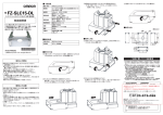
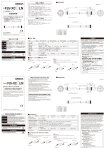
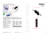
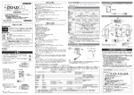
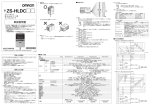
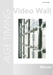
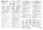
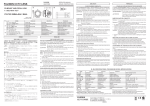
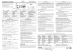
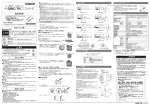
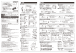
スマート接触式アンプ(判別タイプ)
E9NC-TA0
1
設置編
1-1
外形寸法図
出力切替方法
27.8
4.2
30.2
5.2
13.8
11.5
6.9
10
切替えます。
10
159.7(カバー開時最大)
5
警告
正しい取扱いをしなければ、この危険のために、時に軽傷・中程度
の傷害を負ったり、あるいは物的損害を受ける恐れがあります。
安全を確保する目的で直接的または間接的に人体を検出する用途に本製
品は使用できません。人体保護用の検出装置として本製品を使用しない
でください。
故障や発火の恐れがあります。
定格電圧を超えて使用しないでください。
破裂の恐れがあります。
AC電源では絶対に使用しないでください。
安全上の要点
以下に示す項目は安全を確保するうえで必要なことですので必ず守ってください。破損・発火の恐れがあります。
・下記の設置場所では使用しないでください。
①直射日光が当たる場所
②湿度が高く、結露する恐れがある場所
③腐食性ガスのある場所
④振動や衝撃が定格の範囲を超える場所
⑤水・油・化学薬品の飛沫がある場所
⑥蒸気の当たる場所
⑦強電界・強磁界のある場所
・引火性、爆発性ガスの環境では使用しないでください。
・定格を超える周囲雰囲気・環境では使用しないでください。
・操作や保守の安全性を確保するため、高圧機器や動力機器から離して設置してください。
・ケースが破損した状態で使用しないでください。
・火傷の恐れがあります。使用条件(周囲温度、電源電圧、他)
によってはセンサ表面温度が高くなります。操作
時や清掃時にはご注意ください。
・センサ設定時は、装置を停止していただく等、安全をご確認された上で行ってください。
・配線を着脱するときは、
必ず電源を切ってから行ってください。
・本体の分解、修理・改造をしないでください。
・廃棄するときは、産業廃棄物として処理してください。
・電源の極性など、誤配線をしないでください。
・水中、降雨中、
および屋外での使用は避けてください。
・対応規格
①EN61326-1
②Electromagnetic environment : Industrial electromagnetic environment (EN/IEC 61326-1 Table 2)
使用上の注意
・DINレールへの取り付け時には、
カチッと音がするまで取り付けてください。
・感電や短絡防止のため、使用しない連結用電源端子には保護用キャップ
(センサ通信ユニット
:形E3NWシリー
ズに付属)
を付けてください。
保護用キャップ
32.1
(49.5)
(39.3)
102.4
光通信部
DINレール(PFP-□N)別売り
● 警告表示
警告
3.9
0
26
(29.9)
安全上のご注意
● 警告記号の意味
37
33.5
3.4
* 4 0 1 3 2 6 8 - 0 E *
© OMRON Corporation 2014 All Rights Reserved.
152°(カバー開時最大)
19.2
114(カバー開時最大)
2.6
( ) 内の寸法は関連部品との寸法になります。
カバーを 152 度以上傾けると外れる事があります。
1-2
単位:mm
アンプユニットの取付け
■DIN レールへの取付け
(1) センサヘッド挿入部側のツメをレールにかけます。
(2) フックがカチッと音がするまで押し込みます。
■DIN レールからの取外し
センサヘッド挿入部側のツメ
(1) 本体を矢印 1 の方向へ押します。
(2) (1) をしながら矢印 2 の方向へ持ち上げます。
2
1
■連結して使用する場合
DINレール
(1) アンプユニットを1台ずつDINレールに取り付けま
す。
通信コネクタが密着するまで、アンプユニットをスラ
イドさせます(矢印3)
(2) 振動で離れないように、別売のエンドプレート(形
PFP-M)でアンプをしっかりとはさんでください。
(矢印4)
(3) ドライバでエンドプレートのネジを締めてください。
(矢印5)
最大連結可能台数は、各 E3NW シリーズ通信ユニットの仕
様をご確認してください。
必ずエンドプレートを使用してください。
1-3
3
4
5
押しながらネジを締めてください。
センサヘッドの取付け
1
1.
2.
保護カバーを開けます。
センサヘッドのコネクタ部のロックレバーが
上になるように向け、コネクタ挿入口に奥ま
で差し込みます。
E9NC-TH はコネクタカバーが黄色になって
いますので確認して誤接続のないように取付
けお願いします。
取外しは、ロックレバーを押しながら、引き
抜いてください
2
ロックレバー
コネクタカバー
(黄色)
・センサヘッドのコネクタ部をアンプユニットに固定した状態で、
引っ張り、圧縮、
ねじりなどの無理な力を加えないで
ください。
・保護カバーは必ず装着した状態で使用してください。誤動作の危険があります。
・電源投入直後は使用環境に応じて測定値が安定するまで時間がかかる場合があります。
・モバイルコンソール形E3X-MC11、形E3X-MC11-SV2、形E3X-MC11-Sは使用できません。
・センサ通信ユニット形E3NW-ECT/CCLが使用できますが、形E3X-DRT21-S、形E3X-CRT/ECT、形
E3NW-CRTは使用できません。
・万が一、異常を感じたときには、
すぐに使用を中止し、電源を切った上で、
当社支店・営業所までご相談ください。
・清掃にはシンナー、
ベンジン、
アセトン、灯油類は使用しないでください。
パッケージ内容の確認
・アンプユニット 1台 ・取扱説明書(本書) 各1部(日本語 英語 中国語)
対応通信ユニット
(別売り)
E3NWシリーズ通信ユニット, 分散ユニット 形E3NW-DS
E9NC-TA0
10.
4∼13 を有効にしたいとき
11.
12.
Eco on
表示灯 ( 白デジタル ) が消灯します。
ボタン操作すると、約 10 秒間点灯した後、消灯します。
2 出力への信号割り当てを指定します。
ec%
エコ機能 LO
l%
Eco Lo
ボタン操作すると、約 10 秒間点灯した後、
表示灯 ( 白デジタル ) が低輝度で点灯します。
500
13.
ご承諾事項
電源をきり、センサ通信ユニット用コネクタが短絡していないか
ご確認後、電源を再投入してください。
形式
制御出力数
表示分解能
接続方式
電源電圧
消費電力
制御出力
保護回路
周囲温度範囲
電源を再投入してください。
それでも復帰しない場合は、設定初期化を実行してください。
周囲湿度範囲
絶縁抵抗
耐電圧
振動(耐久)
衝撃(耐久)
質量(梱包 / 本体)
材質
形 E9NC-TA0
2
最小 0.1μm
センサ通信ユニット用コネクタ
通信ユニットを通してコネクタより供給
電源電圧 24V 通常モード :2040mW 以下 (消費電流 85mA 以下) エコ機能 ON :1800mW 以下(消費電流 75mA 以下)
エコ機能 LO:1920mW 以下(消費電流 80mA 以下) 通信ユニッ
トの仕様を参照してください。
電源逆接保護、出力短絡保護
動作時:1 ∼ 2 台連結時:0℃∼ +55℃、3 ∼ 10 台連結時:0℃∼ +50℃、
11 ∼ 16 台連結時:0℃∼ +45℃、17 ∼ 30 台連結時:0℃∼ +40℃
保存時: -30℃∼ +70℃
(ただし、氷結、結露しないこと)
動作時・保存時:各 35 ∼ 85%RH(ただし、結露しないこと)
20MΩ以上(DC500V メガにて)
AC1,000V 50/60Hz 1min
10 ∼ 55Hz 複振幅 1.5mm X、Y、Z 各方向 2h
150m/s2 X、Y、Z 各方向 3 回
約 65g/ 約 25g
ケース、カバー : ポリカーボネート(PC)
当社商品は、一般工業製品向けの汎用品として設計製造されています。従いまして、次に
掲げる用途での使用を意図しておらず、
お客様が当社商品をこれらの用途に使用される際
には、当社は当社商品に対して一切保証をいたしません。
ただし、次に掲げる用途であって
も当社の意図した特別な商品用途の場合や特別の合意がある場合は除きます。
(a) 高い安全性が必要とされる用途
(例:原子力制御設備、燃焼設備、航空・宇宙設備、鉄
道設備、昇降設備、娯楽設備、医用機器、安全装置、
その他生命・身体に危険が及び
うる用途)
(b) 高い信頼性が必要な用途
(例:ガス・水道・電気等の供給システム、24時間連続運転
システム、決済システムほか権利・財産を取扱う用途など)
(c) 厳しい条件または環境での用途
(例:屋外に設置する設備、化学的汚染を被る設備、
電磁的妨害を被る設備、振動・衝撃を受ける設備など)
(d) カタログ等に記載のない条件や環境での用途
*(a)から(d)に記載されている他、本カタログ等記載の商品は自動車
(二輪車含む。以下同
じ)
向けではありません。自動車に搭載する用途には利用しないで下さい。自動車搭載
用商品については当社営業担当者にご相談ください。
*上記は適合用途の条件の一部です。当社のベスト、総合カタログ、データシート等最新版
のカタログ、
マニュアルに記載の保証・免責事項の内容をよく読んでご使用ください。
インダストリアルオートメーションビジネスカンパニー ●製品に関するお問い合わせ先
お客様相談室
0120-919-066
クイック
オムロン
携帯電話・PHS・IP電話などではご利用いただけませんので、
下記の電話番号へおかけください。
電話
055-982-5015(通話料がかかります)
■営業時間:8:00∼21:00 ■営業日:365日
●FAXやWebページでもお問い合わせいただけます。
FAX
055-982-5051 / www.fa.omron.co.jp
●その他のお問い合わせ
納期・価格・サンプル・仕様書は貴社のお取引先、または貴社
担当オムロン販売員にご相談ください。
オムロン制御機器販売店やオムロン販売拠点は、Webページで
ご案内しています。
A v 2 0 1 4 年7月
E9NC-TA0
1 Installation
E9NC-TA0
1-1 Dimensions
Output switching
27.8
5.2
13.8
11.5
6.9
10
4.2
30.2
Indicates a potentially hazardous situation which, if not avoided,
WARNING may result in minor or moderate injury or in property damage.
Warning Indications
WARNING
This product is not designed or rated for ensuring safety of persons
either directly or indirectly. Do not use it for such purpose.
Do not use the product with voltage in excess of the rated voltage.
Excess voltage may result in malfunction or fire.
Never use the product with an AC power supply. Otherwise,
explosion may result.
PRECAUTIONS FOR SAFE USE
The following precautions must be observed to ensure safe operation of the product. Doing so may cause
damage or fire.
· Do not install the product in the following locations.
(1) Locations subject to direct sunlight
(2) Locations subject to condensation due to high humidity
(3) Locations subject to corrosive gas
(4) Locations subject to vibration or mechanical shocks exceeding the rated values
(5) Locations subject to exposure to water, oil, chemicals
(6) Locations subject to steam
(7) Locations subjected to strong magnetic field or electric field
· Do not use the product in environments subject to flammable or explosive gases.
· Do not use the product in any atmosphere or environment that exceeds the ratings.
· To secure the safety of operation and maintenance, do not install the product close to high-voltage
devices and power devices.
· Do not use the product if the case is damaged.
· Burn injury may occur. The product surface temperature rises depending on application conditions, such
as the ambient temperature and the power supply voltage. Use caution when operating or cleaning the
product.
· When setting the sensor, be sure to check safety such as by stopping the equipment.
· Be sure to turn off the power supply before connecting or disconnecting wires.
· Do not attempt to disassemble, repair, or modify the product in any way.
· When disposing of the product, treat it as industrial waste.
· Do not miswire such as the polarity of the power supply.
· Do not use on underwater, rain or the outdoors.
· Applicable standards
(1)EN61326-1
(2)Electromagnetic environment : Industrial electromagnetic environment (EN/IEC 61326-1 Table 2)
PRECAUTIONS FOR CORRECT USE
· Be sure to mount the unit to the DIN track until it clicks.
· To prevent electric shock or short circuit, put a protection cap (attached with Sensor communication unit
E3NW) on unused connection power supply terminals.
Protective Cap
· Do not apply excessive force such as tension, compression or torsion to the connector of the sensor head
that is fixed to the amplifier unit.
· Always keep the protective cover in place when using the product. Not doing so may cause malfunction.
· It may take time until the received measured value become stable immediately after the power is turned
on depending on use environment.
· The Mobile Console E3X-MC11, E3X-MC11-SV2 and E3X-MC11-S cannot be connected.
· Sensor communication unit E3NW-ECT/CCL can be used. E3X-DRT21-S, E3X-CRT/ECT and
E3NW-CRT cannot be used.
· If you notice an abnormal condition such as a strange odor, extreme heating of the unit, or smoke,
immediately stop using the product, turn off the power, and consult your dealer.
· Do not use thinner, benzine, acetone, and lamp oil for cleaning.
• Amplifier Unit: 1
5
3.9
0
32.1
(49.5)
DIN RALL(PFP-□N)
(SOLD SEPARATELY)
26
(29.9)
PRECAUTIONS ON SAFETY
Meanings of Signal Words
152°(Max. with the protective cover open)
37
33.5
3.4
* 4 0 1 3 2 6 8 - 0 E *
2014
159.7(Max. with the protective cover open)
2.6
19.2
The following notice applies only to products that carry the CE mark:
Notice:
This is a class A product. In residential areas it may cause radio
Interference,in which case the user may be required to take adequate
measures to reduce interference.
114(Max. with the protective cover open)
10
OPTICAL
COMMUNICATION
POSITION
(39.3)
102.4
Dimensions in parentheses () indicates the ones with related components.
The cover could come off if it is tilted by 152 degrees or more.
Unit: mm
1-2 Mounting the Amplifier Unit
■Mounting on DIN Track
(1) Let the hook on the Amplifier Unit's Sensor Head
connection side catch the track.
(2) Push the unit until the hook clicks into place.
■Removing from DIN Track
(1) Push the unit in the direction 1.
(2) Lift the unit in the direction of arrow 2 while
performing step (1).
Fiber Unit Connection Side Hook
2
1
DIN Track
■Joining Amplifier Units
3
(1) Mount the Amplifier Units one at a time onto the DIN track.
Slide the Amplifier Unit until the communication connector is
closely attached.(Arrow 3)
(2) Use End Plates (PFP-M: separately sold) at the both
ends of the grouped Amplifier Units to prevent them from
separating due to vibration or other cause.(Arrow 4)
(3) Tighten the screw on the End Plates using a driver.(Arrow 5)
4
5
Tighten the screw while pressing the End Plate.
For the maximum number of units that can be connected,
refer to the specifications of each E3NW Series
Communication Unit.
Always use the End Plates.
1-3 Mounting the sensor head
1. Open the protection cover.
2. Insert the sensor head, with the lock lever on
1
its connector area facing upward, all the way
into the connector port.
The color of the connector cover for E9NC-TH is yellow.
Make sure to avoid misconnection by confirming
the cover color in advance.
To remove it, press and hold the lock lever
then pull the sensor head out.
2
Lock Lever
Connector cover: Yellow
Checking the Package Content
• Instruction Sheet (this sheet): 1 (Japanese, English and Chinese)
Compatible Communication Unit (Sold Separately)
E3NW Series Communication Unit, Distribution unit E3NW-DS
E9NC-TA0
10.
Enabling 4 to 13
11.
12.
Eco on
The indicators (white digital) turn OFF.
They turn ON for approx. 10 seconds and then turn OFF
by button operation.
ec%
Eco function LO
l%
Eco Lo
They turn ON for approx. 10 seconds and then
the indicators (white digital) turn ON
with low brightness.
500
13.
Suitability for Use
Turn off the power supply, check whether the Communication
Unit compatible wire-saving connector is short circuited or not,
and then turn on the power supply again.
Turn on the power supply again.
If the restoration fails, reset the settings.
Model
Control output
Display resolution
Connection method
Power supply voltage
Power consumption
E9NC-TA0
2
Minimum 0.1μm
Communication Unit compatible wire-saving connector
Supplied from the connector through the communications units.
Power supply voltage 24V:Normal mode: 2040mW max.(Power consumption 85mA max.)
Eco function ON: 1800mW max.(Power consumption 75mA max.)
Eco function LO: 1920mW max.(Power consumption 80mA max.)
Please refer to the specification of a communication unit.
Control output
Power supply reverse polarity protection, output short-circuit protection
Protection circuit
Operating: 1 to 2 amplifiers connected: 0℃ to 55℃, 3 to 10 amplifiers connected: 0℃ to 50℃,
Ambient temperature
11 to 16 amplifiers connected: 0℃ to 45℃, 17 to 30 amplifiers connected: 0℃ to 40℃
range
Storage: -30℃ to 70℃ (with no icing or condensation)
Ambient humidity range Operating and storage: 35% to 85% RH (with no condensation)
20 MΩ min. (at 500 VDC)
Insulation resistance
1,000 VAC, 50/60 Hz, 1 minute
Dielectric strength
10 to 55 Hz with a 1.5-mm double amplitude for 2 hrs each in X and Y directions
Vibration resistance
150 m/s2, for 3 times each in X, Y and Z directions
Shock resistance
Weight (packed state/sensor) Approx. 65 g/Approx. 25 g
Case and cover: Polycarbonate (PC)
Materials
Omron Companies shall not be responsible for conformity with any standards,
codes or regulations which apply to the combination of the Product in the
Buyer’s application or use of the Product. At Buyer’s request, Omron will
provide applicable third party certification documents identifying ratings and
limitations of use which apply to the Product. This information by itself is not
sufficient for a complete determination of the suitability of the Product in
combination with the end product, machine, system, or other application or
use. Buyer shall be solely responsible for determining appropriateness of the
particular Product with respect to Buyer’s application, product or system.
Buyer shall take application responsibility in all cases.
NEVER USE THE PRODUCT FOR AN APPLICATION INVOLVING
SERIOUS RISK TO LIFE OR PROPERTY WITHOUT ENSURING THAT THE
SYSTEM AS A WHOLE HAS BEEN DESIGNED TO ADDRESS THE RISKS,
AND THAT THE OMRON PRODUCT(S) IS PROPERLY RATED AND
INSTALLED FOR THE INTENDED USE WITHIN THE OVERALL
EQUIPMENT OR SYSTEM.
See also Product catalog for Warranty and Limitation of Liability.
OMRON Corporation
Tokyo, JAPAN
Industrial Automation Company
Contact: www.ia.omron.com
Regional Headquarters
OMRON EUROPE B.V.
Sensor Business Unit
Carl-Benz-Str. 4, D-71154 Nufringen, Germany
Tel: (49) 7032-811-0/Fax: (49) 7032-811-199
OMRON ELECTRONICS LLC
2895 Greenspoint Parkway, Suite 200
Hoffman Estates, IL 60169 U.S.A.
Tel: (1) 847-843-7900/Fax: (1) 847-843-7787
OMRON ASIA PACIFIC PTE. LTD.
No. 438A Alexandra Road # 05-05/08 (Lobby 2),
Alexandra Technopark,
Singapore 119967
Tel: (65) 6835-3011/Fax: (65) 6835-2711
OMRON (CHINA) CO., LTD.
Room 2211, Bank of China Tower,
200 Yin Cheng Zhong Road,
PuDong New Area, Shanghai, 200120, China
Tel: (86) 21-5037-2222/Fax: (86) 21-5037-2200
D s Oct, 2 0 1 4
E9NC-TA0
1
E9NC-TA0
设置
1-1
外形尺寸图
27.8
5.2
13.8
11.5
6.9
10
4.2
30.2
10
159.7(保护罩打开时最大)
5
● 警告标识的含义
警告
若使用不当,则有可能对人身造成轻度或中度伤害,或造成经济损失。
请勿出于安全目的将本产品直接或间接使用在人体检测用途上。
也勿使用在人体保护用的检测装置上。
32.1
(49.5)
(39.3)
102.4
光通信部
DIN 导轨另售 PFP-□-N
● 警告标示
警告
3.9
0
26
(29.9)
安全注意事项
37
33.5
3.4
* 4 0 1 3 2 6 8 - 0 E *
2014
152°(保护罩打开时最大)
19.2
114(保护罩打开时最大)
2.6
单位:mm
()内的尺寸为相关部件的配合尺寸。
保护罩打开角度超过 152 度时可能会脱落。
1-2
放大器的安装
■安装至 DIN 导轨
(1)如右图所示,将探头插入口一侧的钩爪嵌入导轨。
(2)往后下方推压放大器,直至钩爪完全锁定。
可能会引起故障或火灾。
使用时,请勿超过额定电压。
■从 DIN 导轨上拆卸
(1) 如右图所示,将放大器往方向 1 推压。
(2) 同时朝方向 2 提起。
可能会导致产品破裂。
严禁在AC电源下使用。
安全要点
为了确保您的安全,请务必遵守以下内容。否则可能会引起损坏或火灾。
・ 请勿在以下环境中使用。
①阳光直射的场所
②湿度高、易结露的场所
③有腐蚀性气体的场所
④振动或冲击超出额定范围的场所
⑤有水、油、化学药品等飞溅的场所
⑥接触到蒸气的场所
⑦强电场、强磁场的场所
・ 请勿在有易燃、易爆气体的环境下使用。
・ 请勿在超出额定范围的环境下使用。
・ 请将传感器设置在远离高压或动力设备的地方,以免操作或维护时发生危险。
・ 请勿在外壳破损的状态下使用。
・ 可能会导致烫伤。根据使用条件(环境温度、电源电压等)不同,传感器表面温度会升高,
因此在操作或清洁时请多加注意。
・ 设定传感器时请停止装置运行,确认安全后再执行操作。
・ 请务必切断电源后再安装或拆卸导线。
・ 请勿擅自拆卸、修理、改造本产品。
・ 废弃时,请作为工业废弃物处理。
・ 请注意电源的极性,防止错误接线。
・ 请勿在水中,降雨中以及屋外使用。
・ 对应规格
①EN61326-1
②Electromagnetic environment : Industrial electromagnetic environment (EN/IEC 61326-1 Table 2)
使用注意事项
・ 安装至 DIN 导轨时,请推压放大器直至钩爪完全嵌入导轨。
・ 为了防止触电或短路,请在不使用的电源连接端子上,盖上保护盖。(附属于型号 E3NW 系
列传感器通信单元)
探头插入口一侧的钩爪
2
1
■并排使用时
DIN导轨
(1) 将放大器逐一安装至DIN导轨上,靠近并锁
紧各台放大器。( 方向3)
(2) 若要防止因震动而导致的产品移位,请另行
购买边缘导轨(型号PFP-M)来固定放大器。
(方向4)
(3) 请用螺丝刀固定边缘导轨上的螺钉。(方向5)
最多可连接台数请查看各 E3NW 系列通信单元
的规格。
请务必使用终端架。
1-3
1.
2.
3
4
5
按住放大器的同时紧固螺钉
探头的安装
打开保护罩。
如右图所示,将探头的锁定拨杆面朝上,
插入放大器连接器插口的最底部。
E9NC-TH 是黄色连接器保护套,请注意
安装时不要误接。
1
2
拆卸方法为,一边按住锁定拨杆一边向
外拔出。
锁定拨杆 3
连接器保护套(黄色)
4
保护盖
・ 光纤固定于放大器状态下,请勿对其强行施加拉伸力、压缩力、扭转力等。
・ 请务必安装保护罩后使用。可能会导致错误操作。
・ 接通电源后,由于周围环境不同,到测定值安定为止可能需要一定时间。
・ 无法连接手持式控制器型号 E3X-MC11、E3X-MC11-SV2、E3X-MC11-S。
・ 可以连接通信单元型号 E3NW-ECT/CCL,但无法连接型号 E3X-DRT21-S、E3X-CRT、
E3X-ECT、E3NW-CRT。
・ 万一感觉异常时,请立即切断电源停止使用,并联系本公司或代理商。
・ 请不要使用稀释剂,苯,丙酮或煤油类清洁。
包装内容确认
・ 放大器 1 台 ・ 使用说明书(本说明书)日语、英语、中文各 1 份。
支持通信单元(另售)
E3NW 系列通信单元,分散单元型号 E3NW-DS
E9NC-TA0
10.
13
11.
(指定分配于 2 输出的信号)
12.
Eco on
指示灯(白色数字)熄灯。
通过按钮操作后,约亮灯 10 秒钟后即会熄灯。
Eco Lo
ec%
节电功能 低
l%
通过按钮操作后,约亮灯 10 秒钟后,
指示灯(白色数字)即会以低辉度亮灯。
500
13.
承诺事项
型号
判定输出发生短路
通信单元专用连接器
控制输出数
显示分辨率
连接方式
電源電圧
电源电压
控制输出
保护电路
使用环境温度
请重新接通电源。
若无法恢复,请执行设定初始化。
使用环境湿度
绝缘电阻
耐电压
振动(耐久)
冲击(耐久)
重量 ( 捆包 / 净重 )
材质
E9NC-TA0
2
最小 0.1μm
通信单元专用连接器型
通过连接器,由通信单元供给
电源电压 24V 时常规模式:2040mW 以下(消费电流 85mA 以下)
节电功能 ON:1800mW 以下(消费电流 75mA 以下)
节电功能 LO:1920mW 以下(消费电流 80mA 以下)
请参考通信单元的规格
电源逆接保护、输出短路保护
动作状态 : (1~2 台连接 )0℃~ +55℃、(3~10 台连接 )0℃~ +50℃、
(11~16 台连接 )0℃~ +45℃、(17~30 台连接 )0℃~ +40℃
保存状态 : -30℃~ +70℃ ( 无结冰凝露 )
动作和保存状态 : 35~85%RH ( 无结冰凝露 )
20MΩ以上 ( 使用 DC500V 兆欧表 )
AC1,000V 50/60Hz 1min
10 ~ 55Hz 双振幅 1.5mm X、Y、Z 各方向 2h
150m/s2 X、Y、Z 各方向 3 次
约 65g/ 约 25g
外壳、保护罩 : 聚碳酸酯 (PC)
本公司产品是作为工业通用品而设计制造的。因此,不适用于
以下用途,当本公司产品被使用于以下用途时,本公司不做任何
保证。但若是本公司特意为以下用途而设计、或有过特别协商的
情况下,可以用于以下用途。
a) 需要高度安全性的用途(例:用于原子能控制设备、焚烧设备、
航空・宇宙设备、铁道设备、升降设备、娱乐设备、医用器、
安全装置、或其他可能危及到生命・人身安全的用途)
b) 需要高可靠性的用途(例:煤气・水力・电力等的供给系统、
24小时连续运转系统、决裁系统、或其他牵涉到权利・财产的
用途)
c) 苛刻条件或环境下的用途(例:室外设备、易受化学污染的设
备、易受电磁干扰的设备、易受震动・冲击的设备等)
d) 产品手册里未记载的条件或环境下的用途
*除上述a)~d)的记载事项,本产品手册等记载的商品不适用于机
动车(包括两轮车,以下相同)。请勿搭载于机动车上使用。机动
车搭载用商品请咨询本公司销售人员。
*以上是适用条件的一部分。详情请参阅记载于本公司最新版的综
合产品目录、使用手册上的保证・免责事项后再使用。
技术咨询
欧姆龙(中国)有限公司
地址:中国上海市浦东新区银城中路200号
中银大厦2211室
电话:(86)21-5037-2222
技术咨询热线:400-820-4535
网址:http://www.fa.omron.com.cn
c 2013年7月
E9NC-TA0