1
ElectroCraft CompletePower™ Plus Parameter
Version No: 5.0.11
Motion Control Software
Application Manual ElectroCraft
Incorporated
ElectroCraft CompletePower™ Plus Motion Control Software
Title:
ElectroCraft CompletePower™ Plus Parameter Motion Control Software Type of Documentation:
Application Parameter Manual Document Type code:
PM Rev 1.0 09‐18‐09.doc Internal File Reference:
Purpose of Documentation:
Document Number: A11106 This documentation describes… •
ElectroCraft CompletePower™ Plus Drive Parameter Editor tool with Oscilloscope function and program debugging and monitoring descriptions. Record of Revisions:
RELEASE NUMBER 1.0 Copyright:
DATE 09/18/09 DESCRIPTION COMMENTS Initial Release ©2009 ElectroCraft Inc USA. All rights Reserved Copying this document, giving it to others and the use or communication of the contents there of without express authority, is forbidden. Offenders are liable for the payment of damages. We reserve the right to modify our products at any time. Information, specifications, and material data that appear within this user manual are subject to change without notice. For the latest revision of this manual, please check our web site or contact ElectroCraft. Validity: The specified data is for product description purposes only and may not be deemed to be guaranteed unless expressly confirmed in the contract. All rights are reserved with respect to the content of this documentation and the availability of the product
Published by:
ElectroCraft Incorporated P.O. Box 7746, Ann Arbor, Michigan 48107 USA Tel.: 734‐662‐7771 • Fax: 734‐662‐3707 http://www.electrocraft.com Dept.: Sales and Marketing ElectroCraft, Inc.
2
ElectroCraft CompletePower™ Plus Motion Control Software
Table of Contents
1 2 3 ElectroCraft CompletePower™ Plus Parameter …........................................................... 4 1.1 Overview …………................................................................................................... 4 Running ElectroCraft CompletePower™ Plus ……………………………………………………………… 5 2.1 How to Save and Load Parameters .…................................................................ 7 2.2 How to change Drive Parameters ....................................................................... 8 3.0 Description of Parameter and Variables ………………………………………………………… 9 3.1 Identifiers .…........................................................................................................ 9 3.2 Configuration Parameters ……………………………………………………………………………….. 9 3.3 Protection Parameters …………………………………………………………………………………….. 12 3.4 Communication Parameters ………………………………………………………………………….... 14 3.5 Current Loop Parameters ………………………………………………………………………………… 16 3.6 Velocity Loop Parameters ………………………………………………………………………………… 18 3.7 Position Loop Parameters ……………………………………………………………………………….. 23 3.8 Commutation Parameters ……………………………………………………………………………….. 26 3.9 I/O Configuration …………………………………………………………………………………………….. 27 3.9.1 Command Configuration ……………………………………………………………………. 27 3.9.2 Aux Analog Configuration ………………………………………………………………….. 28 3.10 Setting up Data Gathering ……………………………………………………………………………….. 29 3.11 Using Triggering ………………………………………………………………………………………………. 31 3.12 Retrieving Data Gathering Words …………………………………………………………............ 33 3.13 Graphing Variables ………………………………………………………………………………………….. 35 3.14 Function Generator …………………………………………………………………………………………. 43 3.15 Diagnostic Commands and Variables ………………………………………………………………. 45 ElectroCraft, Inc.
3
ElectroCraft CompletePower™ Plus Motion Control Software
1.
ElectroCraft CompletePower™ Plus Parameter 1.1.
Overview Drive parameters are used to configure the drive for different operating modes and to tune the control structure that each operating mode presents. Variables are internal values that change while the Drive is running. Commands are values that cause the drive to do some function e.g. SR3 will cause the drive to go into the run state. Commands will be saved if the drive is reset or powered down. Parameters can be changed using the different parameter screens available in the ElectroCraft CompletePower™ Plus program. Variables can be recorded using the Graph Window. Variables are graphed in the loop tuning tools to evaluate the effectiveness of set Parameters Each command entry is headed by the ASCII command followed by its descriptive label. The allowable value range follows. That is followed by the applications that can make use of this parameter or variable. Finally, the scaling and use of the variable follows. In any formula, the value entered is denoted by ‘X’. The parameters are not typically changed once the user has tuned the drive to a specific application. To read the value: From the terminal page type the ASCII command followed by a return. To write a new value: Type the ASCII command followed by the new value (X) and a return. Backspace allows you to start over in case a mistake is made. ElectroCraft, Inc.
4
ElectroCraft CompletePower™ Plus Motion Control Software
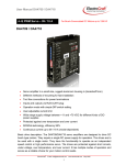
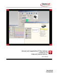
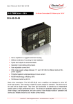
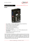
2.0 Running ElectroCraft CompletePower™ Plus After establishing communications with the drive, load drive parameters from a file or disk, by clicking on “File” from the tool bar and then “Open Parameters File” from the drop down box of the tool bar. Locate the file and click open. In figure 1 below, select from pre‐loaded parameter file sets that have been established for use with this drive when using ElectroCraft motors. Figure 1: Read Parameters from File ElectroCraft, Inc.
5
ElectroCraft CompletePower™ Plus Motion Control Software
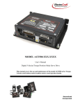
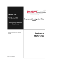
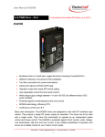
Alternatively, you can read the existing drive parameters stored in the drive. Click on the “Options” icon on the tool bar then select “Drive” and then click the “Retrieve Parameters from Drive” option. Figure 2: Load Parameters from File Once communications have been established and the drive parameters retrieved, they will be displayed. A similar table of drive parameters will then be displayed. Figure 3: Drive Parameter Table The parameter table, see figure 3, lists all of the drive parameters grouped by function type. The current drive parameter value is displayed along with the range of acceptable values, Min to Max, and the parameter’s access level, i.e. R/W stands for Read/Write and R for Read only. For R/W access parameters, the user can both read the value as well as write a new value. Read only parameters store critical calibration values and can only be changed by ElectroCraft Inc personnel. ElectroCraft, Inc.
6
ElectroCraft CompletePower™ Plus Motion Control Software
2.1
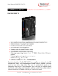
How to Save and Load Drive Parameter Files Note: Before you change any parameter, it is highly recommended that you first save the original parameters to a file so that you can restore them later if needed. Click the “File” icon on the tool bar, and then “Save Parameters”. This selection will bring up a “Save As” dialog box. Name your file, i.e. “default.prm”, and then press the “Save” button in the Applications folder. To open this saved “default.prm” file from your computer, or any previously saved parameter file. Click the “File” icon from your tool bar, then select the “Open Parameters File” icon. Alternatively, select “File” icon from your tool bar, then “Open Parameters File” and search for the desired parameter file on your PC. Opening a file will load the parameters from your computer or diskette to the ElectroCraft CompletePower™ Plus program only. A pop‐up dialog box will appear any time you open a new parameter file from your PC, which will ask if you wish to write the parameters to the drive. If you are not certain that you want to replace the drive parameters with the new parameters then select “No”. The new parameters will be loaded into the Windows program where you can reference them and change them if desired. When the user is ready to upload the new parameters, you must then click the “Options” icon on the tool bar then “Drive”, and then “Write Parameters to Drive” from the menu line. Figure 4: Uploading New Parameters ElectroCraft, Inc.
7
ElectroCraft CompletePower™ Plus Motion Control Software
2.2
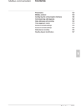
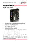
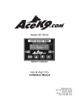
How to Change Individual Drive Parameters Most Drive parameters can be changed at any time while the Drive is operational and will take immediate effect. However, some Drive parameters, if changed, will require the drive to be reset before proceeding. The user may continue to enter other parameters before resetting the drive. CL.CG, CL.HT, CL.PL, CL.EC, CL.PR PL.SC, OR, and TE, if changed, require the drive to be reset before taking effect. Note: Any individual parameter that is changed will be immediately written to the drive. For example, to change the “Velocity Proportional Gain” parameter (VL.KP) found under the “Velocity Loop Parameters” section, move your mouse pointer over the displayed value box and then click on it. This will bring up a pop‐up dialog box as shown in the next frame. To change the value simply type in the new value and hit OK. When the OK key is pressed the new parameter value will be uploaded to the drive immediately, so that the value shown on the Parameter table is always the same as it is in the drive. Figure 5: Changing Parameter Values Note: When parameters are stored or written to the Drive, they are automatically
saved in nonvolatile memory. If power is removed and re‐applied, the Drive will retain any changed values. To restore the default drive values, Open and load the default.prm” file. See 1.5 How to Save and Load Parameter files.
ElectroCraft, Inc.
8
ElectroCraft CompletePower™ Plus Motion Control Software
3.
Description of Parameter and Variables This section describes the parameters with some detail. The parameter identifier (shown in red) can be entered into the drive and saved. Caution: Some of the commands and variables described here require specific knowledge and may cause problems if used incorrectly. These should be used only by someone knowledgeable about the drive. These descriptions below describe the parameter and give some user information about the e •
Range: Shows the allowable numeral entry for the specific drive. •
Applications: Lists the type of drive that the parameter is used with. •
Use: Gives details about the parameter and its usage. 3.1.
Identifiers 3.2.
Configuration Parameters CL.PR: PWM (Current) Modulation Period Range: 1250 to 2666: ACS family/ ACE1XXX/ EBC family 1334 to 2666: ACE500 Applications: All Use: ACS, ACE1XXX, EBC: The current loop and PWM rates in hertz are 7.5*107 / X. Values below 1250 may cause problems. ACE500: The current loop and PWM rates in hertz are 2*107 / X The current loop period = 2 x PR x [CPU clock period] = 2 x PR x [6.67 ns] (for the ACE500) The current loop frequency = [CPU clock frequency] / (2 x PR) = [150 MHz] / 2 x PR (for the ACE500) ElectroCraft, Inc.
9
ElectroCraft CompletePower™ Plus Motion Control Software
CL.CG: Configuration Word Range: 0 to 65535: All products Application: All DSP based drives. Use: ACS family, ACE family, EBC family This command is used to specify what servo loops are running and to control other features of the drive. When this field is clicked in the user interface, a popup appears to allow the user to set this configuration word. Bits Usage 0
On if the position loop is to be used. The position loop will not be used if its output – the input to the velocity loop ‐ is supplanted by using analog velocity feedback. 1
On if the velocity loop is to be used. Note the velocity loop is always on in velocity mode, optional in position mode, and off in current mode. 2 On if velocity is to be computed from encoder edges, off if computed from Hall edges. If using analog velocity feedback, this bit is ignored. Note this bit must be on (and bits 3, 12, and 13 must be off) in order to read the present encoder position using the PL.AC command. (On the ACE‐1000, this bit can only be used if a hardware change is also made.) 3,12,13 If bit 3 is on, and bits 12 and 13 are off, measured velocity comes from analog input feedback (AN2). If bit 3 is off, bit 12 is on, and bit 13 is off, measured position comes from analog input feedback (AN2). If bits 3 and 12 are on, and bit 13 is off, a maximum torque limit comes from analog input feedback (AN2) (not used if in current mode). This is not used for a current mode drive. 4
On if the position command is to be supplied from the serial port. 5
On if sine commutation is to be used (synchronized with a Halls edge), off if trapezoidal commutation is desired. (Note that sine mode is available on older ACE1000 drives only if a hardware change is made.) 6
On if sine commutation is to be used synchronized from the encoder index. Bits 5 and 6 can both be off – meaning trapezoidal commutation is used instead of sine ‐ but both bits cannot be on. (Note that sine mode is available on older ACE1000 drives only if a hardware change is made.) 7
On to allow sine mode over‐modulation. 8 and 9 On the ACE500, these bits are overridden by the Hall Table command CL.HT. For other (older) drives, these bits control which Hall Table to use: If these bits are 0, use the standard 120 degree table. If these bits are 100 hex, use the 120 degree table with Hall S1 and S3 swapped. If these bits are 200 hex, use the standard 60 degree table. If these bits are 300 hex, use the 60 degree table with Hall S1 and S3 swapped. 10
On if encoder direction is reversed. 11
On if command input is analog (AN1). Off for PWM command input. 14 On if sine commutation is to be reversed. ElectroCraft, Inc.
10
ElectroCraft CompletePower™ Plus Motion Control Software
OR: Position/Velocity Loop Rate Range: 3 to 255 Application: Encoder based, velocity mode, or position mode drives. Use: ACS family, ACE family, EBC family The velocity loop rate is ‘current loop rate’ / X. The velocity and position loops run every OR number of current loops. Therefore, e.g., the velocity loop period = [current loop period] x OR. IO: Serial Delay Range: 0 to 256 Application: All Use: ElectroCraft, Inc.
ACS family, ACE family, EBC family For most late model host machines this is typically set to “0”. However, for slower host processors this value inserts a delay in the characters to avoid overflowing the host buffer. 11
ElectroCraft CompletePower™ Plus Motion Control Software
3.3.
Protection Parameters RC: Locked Rotor Current Range: 0 to 1023: ACS family/ ACE1XXX/ EBC family 0‐4096: ACE500 Applications: All Use: RT: ACS family, ACE family, EBC family Used in conjunction with ‘Locked Rotor Time’ to check for locked rotor. If X is zero, the locked rotor check is not performed. Otherwise, the current is checked at every current loop. If the current level is greater or equal to the current level specified for the amount of time specified by locked rotor current without a halls change, a locked rotor fault occurs. The current level is ‘Rated output’ * X / 1024. (ACE500: ‘Rated output’ * X/4096) Locked Rotor Time Range: 0 to 32767: All products Applications: All Use: TE: ACS family, ACE family, EBC family Used in conjunction with ‘Locked Rotor Current’ to check for locked rotor. If the current level is greater or equal to the current level specified for the amount of time specified by locked rotor current without a halls change, a locked rotor fault occurs. X is the time in milliseconds. Motor Temp Control Range: 0 to 2: ACE1000 ‐32767 to 32767: ACE500, ACS family, EBC family Application: All. Use: ACS family, ACE500, EBC family This is used to configure and enable the motor over temperature fault. 0 Motor temperature not used ‐ PTC motor temperature sensor + NTC motor temperature sensor ACE1000 This is used to configure and enable the motor over temperature fault. 0 Motor temperature not used 1 PTC motor temperature sensor 2 NTC motor temperature sensor ElectroCraft, Inc.
12
ElectroCraft CompletePower™ Plus Motion Control Software
LS: Current Control Maximum Command Range: 0 to 1024: ACS family, ACE1xxx, EBC family 0 to 4096: ACE500 Application: All. Use: If the absolute value of current command (CC) is greater than LS, then the current command is set to LS or –LS depending on the sign of CC. LC: Current Control Limit Range: 0 to 1229: ACS family, ACE1xxx, EBC family 0 to 4915: ACE500 Application: All. Use: ACS Family, ACE1xxx, EBC family: If the current feedback (DI) greater than or equal to LC, then the current control filter multiplies the current error (current command – current feedback) by 4. This gives the effect of increasing the current loop gain by 4 when the current is greater than LC. LC is typically set to 1.15 * LS. ACE500: If the current feedback (DI) greater than or equal to LC, then the current control filter multiplies the current error (current command – current feedback) by 4. This gives the effect of increasing the current loop gain by 4 when the current is greater than LC. ElectroCraft, Inc.
13
ElectroCraft CompletePower™ Plus Motion Control Software
3.4.
Communication Parameters CL.EC: Encoder Counts per Rev Range: 0 to 65535 Applications: All applications using an encoder. Use: ACS family, ACE family, EBC family Used for sine wave modulation. Also used by the PC front end to convert internal velocity to RPM. X is the number of encoder counts per mechanical revolution of the motor. (four times the number of encoder lines) CL.PL: Number of Motor Poles Range: 2 to 42 (must be even) Applications: All applications using an encoder. Use: HT: ACS family, ACE family, EBC family Used for sine wave modulation. X is the number of motor poles. Hall Table Range: 0 to 8 Applications: All drives. Use: HP: ACS family, ACE family, EBC family Selects the sequence of Hall states which appear when the motor is rotating. Used in conjunction with the HP command below. Halls Advance Range: 0 to 5 Applications: All drives. Use: ACS family, ACE family, EBC family Advances the 6 step modulation by X states. Used in conjunction with the HT command (above). HP identifies which of the Hall states (in the sequence identified by HT) as the ‘first’ or initial state. ElectroCraft, Inc.
14
ElectroCraft CompletePower™ Plus Motion Control Software
CL.AP: Encoder Advance Range: ‐1024 to 1024 Applications: Sine mode Use: ACS family, ACE family, EBC family Advances the electrical angle by X encoder counts. Used to phase the sine wave output to the motor angle if the halls are not aligned correctly or for index synchronization. If Adv is the number of degrees to advance the encode angle, set CL.AP to ADV * 1024 / 360. For sine mode with halls mode, this should normally be set to zero. The remainder of this page is intentionally left blank.
ElectroCraft, Inc.
15
ElectroCraft CompletePower™ Plus Motion Control Software
3.5.
Current Loop Parameters The current is expressed as units of full scale / 1024. However, if the current is commanded through the analog input, the result is divided by 16 before moving it to the current. CL.KP: Current Proportional Gain Range: 0 to 32767 Application: This is performed every current loop. The Proportional portion of the Voltage Modulation output value is set to KP*‘Current error. Use: ACS family, ACE family, EBC family All drives. CL.KI: Current Integral Gain Range: 0 to 32767 Application: This is performed every current loop. ‘Current error’ * KI/32 is added to ‘working current integral’. Note: changing the KI value will not change the ‘working current integral’. Use: ACS family, ACE family, EBC family All drives. CL.SH: Current Gain Scaling Range: 0 to 7 Application: This is performed every current loop. The Voltage Modulation output value is multiplied by 2SH. Use: ACS family, ACE family, EBC family All drives. CL.EX: Voltage Modulation Limit Plus Range: 0 to 1334: ASC family, ACE1xxx, EBC family 0 to 5000: ACE500 Application: This is an additional restraint to the Voltage Modulation output. CL.DO<= CL.EX <= CL.MX Use: ACS family, ACE family, EBC family All drives. ElectroCraft, Inc.
16
ElectroCraft CompletePower™ Plus Motion Control Software
CL.EN: Voltage Modulation Limit Minus Range: ‐1334 to 1334: ASC family, ACE1xxx, EBC family ‐5000 to 5000: ACE500 Application: This is an additional restraint to the Voltage Modulation output. CL.DO>=CL.EN>=CL.MX Use: ACS family, ACE family, EBC family All drives. The remainder of this page is intentionally left blank.
ElectroCraft, Inc.
17
ElectroCraft CompletePower™ Plus Motion Control Software
3.6.
Velocity Loop Parameters Hall based velocity: The velocity is computed using the 1/T method along with a filter to even out the irregularities in the timing of the halls signals. Internal velocity for halls based is in RPM. Acceleration in RPM per second is ‘internal acceleration’ * ‘velocity loop rate’ / 8. Jerk in RPM per second per second is ‘Jerk’ * ‘velocity loop rate’2 / 2048. Encoder based velocity: The velocity is computed using the 1/T method or counting the number of counts in a velocity loop. The method is changed dynamically when it is deemed advantageous. The internal velocity is in units of ‘counts per velocity loop’ * 256. Therefore, velocity in RPM is ‘internal velocity’ * ‘velocity loop rate’ * (60 / 256) / ‘Encoder Counts per Rev’. Acceleration in RPM per second is ‘internal acceleration’ * ‘velocity loop rate’2 * (60 / 32,768) / ‘Encoder Counts per Rev’. Jerk in RPM per second per second is ‘Jerk’ * ‘velocity loop rate’3 * (60 / 223) / ‘Encoder Counts per Rev’. Analog based velocity: The velocity is supplied by an analog value which will be filtered and have a gain and offset applied. This value may represent velocity or some other physical value such as pressure. A serial command, an analog signal, or the output of the position loop can supply ‘velocity command’. If there is no position loop and the command gain is zero, then the velocity command is from a serial command. The velocity loop is also used to control the drive based on an external analog feedback signal. The ‘velocity error’ is ‘velocity command’ – ‘velocity’. The ‘velocity integral’ is the sum of the ‘velocity errors’. This value is limited by the ‘Velocity Integral Limit’ * 256. The ‘velocity limit’ is not summed if the current or velocity loops are saturated. The ‘velocity derivative’ is (‘old velocity derivative’ * ‘Velocity Derivative Filter’ + (32768 – ‘Velocity Derivative Filter) * (‘velocity error’ – ‘old velocity error’)) / 32768. The output of the velocity loop goes to the current command. VT: Measured Velocity Filter Range: 0 to 32767 Application: Every time a new hall based velocity is computed, the result is filtered. The computed velocity is (‘old computed velocity * X + ‘new velocity’ * (32768 – X)) / 32768. This is also used to filter the velocity command if the position and velocity feedbacks are both encoder, the position command is from step and direction, and both position and velocity loops are active. In this case, the computed velocity command is (‘old velocity command’ * X + ‘new velocity command’ * (32768 – X)) / 32768. Use: ACS family, ACE family, EBC family Halls velocity drives. ElectroCraft, Inc.
18
ElectroCraft CompletePower™ Plus Motion Control Software
VL.KP: Velocity Proportional Gain Range: ‐32768 to 32767 Application: This is performed every velocity loop. ‘Working current correction’ is set to ‘velocity error’ * X. Use: ACS family, ACE family, EBC family Velocity mode or position mode drives. VL.KI: Velocity Integral Gain Range: ‐32768 to 32767 Application: This is performed every velocity loop. ‘Velocity integral’ * X / 256 is added to ‘working current correction’. Use: ACS family, ACE family, EBC family Velocity mode or position mode drives. VL.IL: Velocity Integral Limit Range: 0 to 32767 Application: This is performed every velocity loop. The absolute value of ‘velocity integral’ is limited to 256 * X. Use: ACS family, ACE family, EBC family Velocity mode or position mode drives. VL.KD: Velocity Derivative Gain Range: ‐32768 to 32767 Application: This is performed every velocity loop. ‘Velocity Derivative’ * X is added to ‘working current correction’. Use: ACS family, ACE family, EBC family Velocity mode or position mode drives. ElectroCraft, Inc.
19
ElectroCraft CompletePower™ Plus Motion Control Software
VL.DF: Velocity Derivative Filter Range: 0 to 32767 Application: This is performed every velocity loop. The ‘velocity derivative is set to (‘old velocity derivative’ * X + (‘velocity error’ – ‘old velocity error’) * (32768 – X)) / 32768. Use: ACS family, ACE family, EBC family Velocity mode or position mode drives. VL.SH: Velocity Gain Scaling Range: ‐26 to 30 Application: This is performed every velocity loop. ‘Working current correction’ is multiplied by 2X ‐ 4. Use: ACS family, ACE family, EBC family Velocity mode or position mode drives. VL.MX: Velocity Max Output Range: 0 to 1023: ASC family, ACE1xxx, EBC family ‐0‐4096: ACE500 Application: This is performed every velocity loop. The absolute value of ‘working current correction’ is limited to X and placed in ‘commanded current’. Use: ACS family, ACE family, EBC family Velocity mode or position mode drives. VL.MN: Velocity Max Negitive Output Range: ‐4096 to 0: ASC family, ACE1xxx, EBC family ‐1023 to 0: ACE500 Application: This is performed every velocity loop. The absolute value of ‘working current correction’ is limited to X and placed in ‘commanded current’. Use: ACS family, ACE family, EBC family Velocity mode or position mode drives. ElectroCraft, Inc.
20
ElectroCraft CompletePower™ Plus Motion Control Software
VL.VM: VL.LM: Velocity Max Limit (low order), Velocity Max Limit (high order) Range: ‐2147483648 to 2147483647 Application: . Use: ACE 500 If non zero is used as a fault shut down limit. If velocity > VL.UM then shut down and display fault. VL.CM: Commanded Velocity (low order), VL.CH: Commanded Velocity (high order) Range: –2147483648 to 2147483647 Application: All Use: ACS family, ACE family, EBC family VL.CM when not used as a data gathering variable returns the value of both words together. Both VL.CM and VL.CH need to be used while setting up data gathering to get both words. Units are: 1
RPM for halls based velocity 2
Encoder counts per position servo cycle * 256 for halls based velocity. 3
Filtered analog with gain and offset for if there is no position loop, a velocity loop, and analog velocity is set in the configuration word. Commanded velocity may be written via RS232 only if there is no position loop, a velocity loop is enabled, and the command gain is set to zero. VF.AC: Acceleration Range: 0 to 32767 Application: All applications for which an analog from AN1 (or PWM for the ACE500/1000) is used for the command. Use: ACS family, ACE family, EBC family This command is used every velocity loop unless it is a current mode drive in which case it is used every current loop. If X is zero, then the velocity command is the output of the analog command (if ‘Command Gain’ is nonzero) or the serial command. Otherwise, if ‘Command Gain’ is not zero, X/128 is the maximum amount that the absolute value of the velocity command can change in an update cycle. If X is nonzero, ‘Command Gain’ is zero, and ‘Jerk’ is zero, X/128 represents the absolute value of the change in command every velocity loop. If X is nonzero, ‘Command Gain’ is zero, and ‘Jerk’ is nonzero, X represents the maximum absolute value the internal acceleration can attain. In that case, the internal acceleration divided by 128 represents the change of the velocity command. ElectroCraft, Inc.
21
ElectroCraft CompletePower™ Plus Motion Control Software
VF.JK: Jerk Range: 0 to 32767 Application: Velocity mode drives. Use: ACS family, ACE family, EBC family This command is used every velocity loop unless it is a current mode drive in which case it is unused. This command is not used unless ‘Command Gain’ is zero and ‘Acceleration’ and ‘Jerk’ are nonzero. The jerk is used to generate an s‐curve velocity command profile. The amount that the absolute value of the internal acceleration changes is X/256. The remainder of this page is intentionally left blank.
ElectroCraft, Inc.
22
ElectroCraft CompletePower™ Plus Motion Control Software
3.7.
Position Loop Parameters The position feedback will be from the encoder if the drive is not configured for analog position feedback. The position measurement will then be the number of encoder counts. Otherwise, the position feedback will be from analog. For the ACE500 position, command may come from a step and direction signal, an analog signal, or a serial command. The command is from step and direction if the drive is not configured for a serial position command and command gain is zero. The ‘position error’ is ‘position command’ – ‘position’. The ‘position integral’ is the sum of the ‘position errors’. This value is limited by the ‘Position Integral Limit’ * 256. The ‘position limit’ is not summed if the current loop or the position loop are saturated. The ‘position derivative’ is (‘old position derivative’ * ‘Position Derivative Filter’ + (32768 – ‘Position Derivative Filter) * (‘position error’ – ‘old position error’)) / 32768. The output of the position loop goes to the velocity command if there is a velocity loop. Otherwise, it is divided by 16 and put in the current command. PL.KP: Position Proportional Gain Range: 0 to 32767 Application: This is performed every velocity loop. ‘Working velocity correction’ is set to ‘velocity error’ * X. Use: ACS family, ACE family Position mode drives. PL.KI: Position Integral Gain Range: 0 to 32767 Application: This is performed every velocity loop. ‘Position integral’ * X / 256 is added to ‘working velocity correction’. Use: ACS family, ACE family Position mode drives. ElectroCraft, Inc.
23
ElectroCraft CompletePower™ Plus Motion Control Software
PL.IL: Position Integral Limit Range: 0 to 32767 Application: This is performed every velocity loop. The absolute value of ‘position integral’ is limited to 256 * X. Use: ACS family, ACE family Position mode drives. PL.KD: Position Derivative Gain Range: 0 to 32767 Application: This is performed every velocity loop. ‘Position derivative’ * X is added to ‘working current correction’. Use: ACS family, ACE family Position mode drives. PL.DF: Position Derivative Filter Range: 0 to 32767 Application: This is performed every velocity loop. ‘Position derivative is set to (‘old position derivative’ * X + (‘position error’ – ‘old position error’) * (32768 – X)) / 32768. Use: ACS family, ACE family Position mode drives. PL.SH: Position Gain Scaling Range: ‐30 to 30 Application: This is performed every velocity loop. ‘Working velocity correction’ is multiplied by 2X. Use: ACS family, ACE family Position mode drives. ElectroCraft, Inc.
24
ElectroCraft CompletePower™ Plus Motion Control Software
PL.MX: Position Max Output Range: 0 to 32767 Application: Position mode drives. Use: ACS family, ACE family This is performed every velocity loop. The absolute value of ‘working velocity correction’ is limited to X * 16. ‘Commanded velocity’ is set to (‘position command’ – ‘old position command’) * 256 + ‘working velocity correction’ PL.SC: Steps per Revolution Application: Position mode drives. Command Gain (VF.GN) must be zero and the Configuration word must not be set for serial position command. Use: ACS family, ACE family This is performed every velocity loop. Every step pulse while the drive is in run, the desired position is incremented or decremented (depending on the direction signal) by Encoder Counts per Rev (CL.EC) / Steps per Revolution. The calculation is accurate to within one encoder count both within one revolution and long term. This will try to position the motor as if it were a stepper motor with the correct number of steps for one revolution. Unfortunately, because of an error in the DSP silicon, the first step is always lost. If position feedback is encoder and velocity command is step and direction, the velocity command is incremented by 256 * encoder count difference in addition to the velocity command from the position PID loop. ElectroCraft, Inc.
25
ElectroCraft CompletePower™ Plus Motion Control Software
3.8.
Commutation Parameters HT Hall Table Range: 0 to 8 Applications: All. Use: ACS family, ACE family, EBC family Selects the sequence of Hall states which appear when the motor is rotating. Used in conjunction with the HP command below. The remainder of this page is intentionally left blank.
ElectroCraft, Inc.
26
ElectroCraft CompletePower™ Plus Motion Control Software
3.9.
I/O Configuration 3.9.1. Command Configuration VF.FL: Command Filter Range: 0 to 32767 Application: All applications for which an analog from AN1 is used for the command. Use: ACS family, ACE family, EBC family This is used every velocity loop unless the drive is in current mode only in which case it is used every current loop. This is used for the first operation in converting the analog command to an actual command. The output of this command is used as the input to the ‘Command Offset’. This command may represent position, current, velocity, or a value represented by the analog feedback signal. The output of the filter is (‘Old Value’ * X + ‘New Value’ * (32768 – X)) / 32768. VF.OF: Command Offset Range: ‐32768 to 32767 Application: All applications for which an analog from AN1 is used for the command. Use: ACS family, ACE family, EBC family This command is used every velocity loop unless it is a current mode drive in which case it is used every current loop. Used as the second operation in converting the analog command to an actual command. The output of this command is used as the input to the ‘Command Gain’. X is added to the input to get the output. VF.GN: Command Gain Range: ‐32768 to 32767 Application: All applications for which an analog from AN1 is used for the command. Use: ElectroCraft, Inc.
ACS family, ACE family, EBC family This command is used every velocity loop unless it is a current mode drive in which case it is used every current loop. Used as the third operation in converting the analog command to an actual command for the outer loop used. If the gain is zero, then there is no analog command and the command must be provided serially or by step and direction for position mode. Note that step and direction is not available on the ACE500/1000. The output is ‘input’ * X / 4096 for current command or ‘input’ * X / 256 for velocity or position command. The output is the command in internal units. 27
ElectroCraft CompletePower™ Plus Motion Control Software
3.9.2. Aux Analog Configuration Can be used as a torque limit, velocity feedback or position feedback. CF.FL: Aux Analog Filter Range: 0 to 32767 Application: All. Use: ACS family, ACE family, EBC family This is used every velocity loop unless the drive is in current mode only in which case it is used every current loop. This is used for the first operation in converting the analog feedback to an actual feedback. The output of this command is used as the input to the ‘Aux Analog Offset’. This feedback may represent position, velocity, or a current limit. The output of the filter is (‘Old Value’ * X + ‘New Value’ * (32768 – X)) / 32768. The input range is 0 to 8191. CF.OF: Aux Analog Offset Range: ‐32768 to 32767 Application: All. Use: ACS family, ACE family This is used every velocity loop unless it is a current mode drive in which case it is used every current loop. Used as the second operation in converting the analog feedback to an actual feedback or current limit. The output of this command is used as the input to the ‘Command Gain’. X is added to the input to get the output. CF.GN: Aux Analog Gain Range: ‐32768 to 32767 Application: All applications for which an analog AN2 is used. Use: ACS family, ACE family This is used every velocity loop unless it is a current mode drive in which case it is used every current loop. Used as the third operation in converting the analog feedback to an actual feedback. The output is ‘input’ * X / 256. The output is the feedback in internal units. ElectroCraft, Inc.
28
ElectroCraft CompletePower™ Plus Motion Control Software
3.10. Setting up Data Gathering DG.DW: Start up Delay Range: Special, see comments below Application: All. Use: ACS family, ACE family, EBC family The number of sample periods to delay before starting the first sample. This variable may have a value from 0 to 32767. If there is triggering, the value may be from –32767 to 32767. If the value is negative, its absolute value must be less than or equal to the number of samples able to be collected (see DG.DE). DG.DR: Sample Rate Range: 0 to 65535 Application: All. Use: ACS family, ACE family, EBC family The number of current or position loops – 1 between each sample period. DG.DS: Data Specification Start Range: 0 to 1, see comments below Application: All. Use: ACS family, ACE family, EBC family Specifies current loop (1) or position loop (0). After this command the variables desired must be entered. This variable must either have a value of 1 or zero. If triggering is to be used, it must be set up before this command is issued. ElectroCraft, Inc.
29
ElectroCraft CompletePower™ Plus Motion Control Software
DG.DE: Data Specification End Range: 0 to 32767 Application: All. Use: ACS family, ACE family, EBC family Specifies the number of samples to collect. All the variables desired must be entered before this command. Each sample has the number of variables entered between the data specification start and the data specification end. Note that if a variable is double precision, the location of the variable and the location of the high order of the variable must both be specified. The maximum number of samples is (32767 – 5 * Number of single precision triggers – 7 * Number of double precision triggers) / Number of variables specified. The remainder of this page is intentionally left blank.
ElectroCraft, Inc.
30
ElectroCraft CompletePower™ Plus Motion Control Software
3.11. Using Triggering No Trigger If there is no trigger, a sample is collected every sample period after a delay of a specified number of sample periods. A sample is a snapshot of the variables specified during the data gathering setup. A sample period is a specified number of current or velocity loops. There are 32768 words available to store the samples. The space required to store all the samples is # of variables * (number of samples + 1). Note that double precision variables such as commanded velocity require two words to store. To set up data gathering, set the start up delay and the sample rate as desired followed by a data specification start, then list the variables in order that you want, then the data specification end. Trigger If triggering is desired, then a negative sample delay is the number of samples before the trigger event to be displayed and a positive sample delay is the number of samples after the trigger event to delay. No data will be sent until the trigger event occurs. DG.TC: Clear trigger table Use: ACS family, ACE family, EBC family This must be the first command before setting up the trigger table if there is to be one. This command clears both the trigger table and the data gathering table. DG.TR: Set the trigger control word Use: Bits 15
ACS family, ACE family, EBC family This sets the trigger control word. The trigger control word cannot be read. This command must be directly followed by a command which is the command to read the data variable. The data variable must be followed by a DG.CN command. Description Must be set to zero. 13‐14
Comparison type which takes one of these four values: •
0: Variable < constant •
1: Variable > constant •
2: Falling edge, Variable was greater or equal to constant, now is less •
3: Rising edge, Variable was less or equal to constant, now is greater 11‐12
Relationship type which takes one of these four values: •
0: Last entry in table •
1:Both this comparison and the next one must be true •
2: Either this comparison or the next must be true •
3: This comparison must become true and then the next one must become true 9‐10
Variable type which takes one of the following three values: •
0: Variable and constant are unsigned •
2: Variable is signed, constant is unsigned and comparison is absolute value •
3: Variable and constant are signed 8
On for double precision variable and constant 0‐7
ElectroCraft, Inc.
Filter 31
ElectroCraft CompletePower™ Plus Motion Control Software
Filter operation: Use: ACS family, ACE family, EBC family Let FO be the old filtered value (with fraction), FN be the new filtered value, F be the filter and V be the actual variable value. Then: FN = (V * F + (256 – F) * FO) / 256. DG.CN: Set the trigger constant Use: ACS family, ACE family, EBC family This sets the trigger constant. The constant is signed or unsigned and single or double precision depending on the value of the DG.TR command. The trigger constant cannot be read. This command must be directly preceded by a command that specifies the data variable desired. The remainder of this page is intentionally left blank.
ElectroCraft, Inc.
32
ElectroCraft CompletePower™ Plus Motion Control Software
3.12. Retrieving Data Gathering Words DG.RM: Data Read Use: ACS family, ACE family, EBC family This variable is read only. Read a word of data from data gathering memory. The value is returned in hexadecimal. The values are returned in sample number order and within samples in order by the data variables entered. DG.ST: Data Read Streaming Use: ACS family, ACE family, EBC family This command starts data streaming. The number of samples to be returned are in the command parameter. Each variable is returned as two 8 bit characters. After all data is streamed, a carriage return followed by a line feed is put out. It is up to the user to make sure the number of points specified are available before issuing this command (see DG.PA). The values are sent in the same order as DG.RM. DG.PA: Data Points Remaining Use: ACS family, ACE family, EBC family This variable is read only. Returns the total number of points, which have been collected but not read. DG.DA: Data Address Use: ElectroCraft, Inc.
ACS family, ACE family, EBC family This variable is the number of words, which have been read. This can be used in conjunction with data CRC to set the back to the place where the CRC was last valid in case the CRC does not match. 33
ElectroCraft CompletePower™ Plus Motion Control Software
DG.CR: Data CRC Range: 0 to 65535 Application: All. Use: ACS family, ACE family, EBC family For every word which is read by way of a read data command, a CRC is computed by the code shown below. When Data CRC is written, it is written to the upper 16 bits of GraphCRC. When DataCRC is read, it is read from the upper 16 bits of GraphCRC. By setting GraphCRC to a known number from 0 to 65535 (65535 is recommended) and keeping track of the CRC as each data word is sent, the data can be verified with a very small probability of undetected error. unsigned long int GraphCRC; unsigned short int Data; Graphic CRC += Data; for (Ix = 0; Ix < 16; Ix++) { if ((long int)GraphCRC < 0) GraphCRC ^= 0xC0028000; GraphCRC <<= 1; } The remainder of this page is intentionally left blank.
ElectroCraft, Inc.
34
ElectroCraft CompletePower™ Plus Motion Control Software
3.13. Graphing Variables Variables are used for data gathering and graphing. Any parameter or variable that can be read can be graphed. These are the variables used by the Windows interface. CL.CC or: Commanded Current CC Range: –1024 to 1024: ACS family, ACE1xxx, EBC family –4096 to 4096: ACE500 Application: All. Use: ACS family, ACExxx, EBC family Units are full scale current / 1024. Commanded current can only be written if there is no position or velocity loop and command gain is zero. ACE500 Units are full scale current / 4096. Commanded current can only be written if there is no position or velocity loop and command gain is zero PL.CM: Commanded Position (low order), PL.CH: Commanded Position (high order) Range: –2147483648 to 2147483647 Application: All. Use: ACS family, ACE family PL.CM when not used as a data‐gathering variable returns the value of both words together. Both PL.CM and PL.CH need to be used while setting up data gathering to get both words. Units are encoder counts if serial position command is off and command gain is zero, filtered analog with gain and offset if serial position command is off and command gain is not zero, or a serial command. Commanded position may be written only if there is a position loop and the serial position bit of the configuration is set. ElectroCraft, Inc.
35
ElectroCraft CompletePower™ Plus Motion Control Software
VL.CM: Commanded Velocity (low order), VL.CH: Commanded Velocity (high order) Range: –2147483648 to 2147483647 Application: All. Use: ACS family, ACE family, EBC family VL.CM when not used as a data‐gathering variable returns the value of both words together. Both VL.CM and VL.CH need to be used while setting up data gathering to get both words. Units are: 1. RPM for halls based velocity 2. Encoder counts per position servo cycle * 256 for halls based velocity. 3. Filtered analog with gain and offset for if there is no position loop, a velocity loop and analog velocity is set in the configuration word. Commanded velocity may be written only if there is no position loop, a velocity loop and the command gain is zero. CL.DO or: Commanded Voltage Application: DO Range: All. Use: +/‐PR/2: ACS family, ACE1xxx, EBC family +/‐PR/2: ACE500 ACS family, ACE family, EBC family Current control loop output used to control % on time of the drive’s output voltage. This value is read only. To calculate the drive output, multiply the rail voltage and divide by ½ of the value of PR. DI: Current Range: –1024 to 1024: ACS family, ACE1xxx, EBC family –4096 to 4096: ACE500 Application: All. Use: ACS family, ACE family, EBC family This is the current that the drive is delivering to the motor. CL.ER or Current Error ER: Application: All. Use: ACS family, ACE family, EBC family This variable is read only. Current error is commanded current – current. ElectroCraft, Inc.
36
ElectroCraft CompletePower™ Plus Motion Control Software
CL.IN or Current Integral (low order) IN: CL.IH or Current Integral (high order) IH: Range: –2147483648 to 2147483647 Application: All. Use: ACS family, ACE family, EBC family This variable is read only. The current integral is the sum of the current errors. The integral is not summed if the current loop is saturated. IN or CL.IN when not used as a data gathering variable returns the value of both words together. Both IN or CL.IN and IH or CL.IH need to be used while setting up data gathering to get both words.. VF.VD: Filtered Command (low order), VF.VA: Filtered Command (high order) Application: All. Use: ACS family, ACE family, EBC family This variable is read only. See command filter (VF.FL) for details about how the filter operates. When not used as a data gathering variable, VF.VA returns the integer part of the filtered command and VF.VD returns both the integer and fractional parts * 65536. CF.VD: Filtered Feedback (low order), CF.VA: Filtered Feedback (high order) Application: All. Use: ACS family, ACE family, EBC family This variable is read only. See aux. analog filter (CF.FL) for details about how the filter operates. When not used as a data gathering variable, CF.VA returns the integer part of the filtered feedback and CF.VD returns both the integer and fractional parts * 65536. PL.DD: Filtered Position Derivative (low order), PL.DE: Filtered Position Derivative (high order) Application: All. Use: ACS family, ACE family, EBC family This variable is read only. See position loop description and position derivative filter (PL.DF) for descriptions of the position derivative. When not used as a data gathering variable, PL.DE returns the integer part of the position derivative and PL.DD returns both the integral and fractional parts * 65536. ElectroCraft, Inc.
37
ElectroCraft CompletePower™ Plus Motion Control Software
VL.DD: Filtered Velocity Derivative (low order), VL.DE: Filtered Velocity Derivative (high order) Application: All. Use: ACS family, ACE family, EBC family This variable is read only. See velocity loop description and velocity derivative filter (VL.DF) for descriptions of the velocity derivative. When not used as a data gathering variable, VL.DE returns the integer part of the velocity derivative and VL.DD returns both the integral and fractional parts * 65536. CL.ID: Flux Current Application: Sine mode only. Use: ACS family, ACE family, EBC family This variable is read only. The DSP program calculates this value. It is the amount of current that is flowing in the drive that is perpendicular to the torque producing current. Because this current causes the motor to generate heat, the ideal value should be zero. CL.DV: Flux Voltage Application: Sine mode only. Use: ACS family, ACE family, EBC family This variable is read only. The DSP program calculates this value. It is the leading (+) or lagging (‐) voltage that the drive is applying to the motor to reduce the flux current. CH: CH: Halls Application: All. Use: ACS family, ACE family, EBC family This value is read only. The three hall signals are displayed as 0 or 1 in the order of s3,s2 & s1 and is the actual value of the three halls signals as read at the DSP. ElectroCraft, Inc.
38
ElectroCraft CompletePower™ Plus Motion Control Software
MP: Motor Phase Range: Value is from 0 to 5 Application: All. Use: ACS family, ACE family, EBC family This value is read only. The motor phase derived from the halls. DU: Phase U Current Range: –1024 to 1024 (proportional the phase U current): ACS family, ACE1xxx, EBC family ‐4096 to 4096 for ‐100 to + 100% current rating: ACE500 Application: All. Use: ACS family, ACE family, EBC family This value is read only. To calculate the actual current multiply by (IR)* (drive rating in amps)/2017152. This value is read only. Value is proportional the phase V current. To calculate the actual current multiply by* (drive rating in amps)/1024 (4096 ACE500). DV: Phase V Current Range: –1024 to 1024 (proportional the phase V current): ACS family, ACE1xxx, EBC family ‐4096 to 4096 for ‐100 to + 100% current rating: ACE500 Application: All. Use: ACS family, ACE family, EBC family This value is read only. To calculate the actual current multiply by (IR)* (drive rating in amps)/2017152. This value is read only. Value is proportional the phase V current. To calculate the actual current multiply by* (drive rating in amps)/1024 (4096 ACE500). ElectroCraft, Inc.
39
ElectroCraft CompletePower™ Plus Motion Control Software
DW: Phase W Current Range: –1024 to 1024 (proportional the phase W current): ACS family, ACE1xxx, EBC family ‐4096 to 4096 for ‐100 to + 100% current rating: ACE500 Application: All. Use: ACS family, ACE family, EBC family This value is read only. To calculate the actual current multiply by (IR)* (drive rating in amps)/2017152. This value is read only. Value is proportional the phase V current. To calculate the actual current multiply by* (drive rating in amps)/1024 (4096 ACE500). PL.AC: Position (low order), PL.AH: Position (high order) Range: –2147483648 to 2147483647 Application: All. Use: ACS family, ACE family, EBC family This variable is read only. PL.AC when not used as a data‐gathering variable returns the value of both words together. Both PL.AC and PL.AH need to be used while setting up data gathering to get both words. Units are encoder counts if analog position feedback command is off or filtered analog with gain and offset if analog position feedback command is off. PL.ER: Position Error Range: –32768 to 32767 Application: All. Use: ACS family, ACE family, EBC family This variable is read only. It is commanded position – position. ElectroCraft, Inc.
40
ElectroCraft CompletePower™ Plus Motion Control Software
PL.IN: Position Integral (low order), PL.IH: Position Integral (high order) Range: –8388352 to 8388352 Application: All. Use: ACS family, ACE family, EBC family This variable is read only. Position integral is the sum of the position errors. It is not accumulated if the position loop or current loop is saturated. PL.IN when not used as a data gathering variable returns the value of both words together. Both PL.IN and PL.IH need to be used while setting up data gathering to get both words. CL.DS: Scaled Current Integral Application: All. Use: ACS family, ACE family, EBC family The portion of the current loop output “DO” due to the integral term of the PI current control. VL.AC: Velocity (low order), VL.AH: Velocity (high order) Range: –2147483648 to 2147483647 Application: All. Use: ACS family, ACE family, EBC family This variable is read only. VL.AC when not used as a data‐gathering variable returns the value of both words together. Both VL.AC and VL.AC need to be used while setting up data gathering to get both words. Units are: 1
RPM for halls based velocity 2
Encoder counts per position servo cycle * 256 for halls based velocity. 3
Filtered analog with gain and offset for if analog velocity is set in the configuration word. VL.ER: Velocity Error Range: –32768 to 32767 Application: All. Use: ACS family, ACE family, EBC family This variable is read only. It is commanded velocity – velocity. ElectroCraft, Inc.
41
ElectroCraft CompletePower™ Plus Motion Control Software
VL.IN: Velocity Integral (low order), VL.IH: Velocity Integral (high order) Range: –8388352 to 8388352 Application: All. Use: ACS family, ACE family, EBC family This variable is read only. Velocity integral is the sum of the velocity errors. It is not accumulated if the velocity loop or current loop is saturated. VL.IN when not used as a data gathering variable returns the value of both words together. Both VL.IN and VL.IH need to be used while setting up data gathering to get both words. CL.EA: Electrical Angle Range: 0 to 1023, (1024 = 360 degrees): ACS Family/ ACE1XXX/ EBC Family Application: Sine mode only. Use: ACS family, ACE family, EBC family The electrical angle may be set to a value and that value will be held regardless of the position until it is changed by writing a new value or released by writing a negative number to the electrical angle. The remainder of this page is intentionally left blank.
ElectroCraft, Inc.
42
ElectroCraft CompletePower™ Plus Motion Control Software
3.14. Function Generator The function generator allows an easy check of the servo response of any of the loops to a generated signal. The generator ramps from the current command to the base of the response signal so that a gradual initial change is provided. FG.SL: Function Generator Ramp Slope Application: All. Use: ACS family, ACE family, EBC family This is the slope of the initial ramp. Units are signal change per loop divided by 256. This is an unsigned number that will adjust the signal upward or downward until the base value is reached. FG.BS: Function Generator Base Value Application: All. Use: ACS family, ACE family, EBC family This is the base of the wave. It is a double precision signed value. FG.AM: Function Generator Amplitude Application: All. Use: ACS family, ACE family, EBC family This is the amplitude of the wave. It is a double precision signed value. The signal value for the main part of the wave generation is between the base and base plus amplitude. Therefore, if the amplitude is negative, the signal will start at the top after the ramp. FG.CY: Function Generator Cycle Time Application: All. Use: ACS family, ACE family, EBC family This is the cycle time for the complete wave. It is a single precision unsigned value. The value is in number of loops. The actual cycle time may be close to this value, but not necessarily exact. ElectroCraft, Inc.
43
ElectroCraft CompletePower™ Plus Motion Control Software
FG.CT: Function Generator Control Word Application: All. Use: ACS family, ACE family, EBC family This is the word, which controls the operation of the function generator. Its format follows: Bits Value Description 0‐1 0 No motion generator 1
Input to current loop 2
Input to velocity loop 3
Input to position loop 0 Square wave 2‐3 1
Triangle wave 2
Sawtooth wave 3
Sine wave (starts at 270°) 4‐5 0 This field must be set to zero by the user FG.ST: Start Function Generation Application: All. Use: ACS family, ACE family, EBC family This command validates the parameters, does some necessary computations, and starts the function generator. If the drive is in standby when this command is issued, the function generator will start when the drive goes into run. FG.SP: Stop Function Generation Application: All. Use: ACS family, ACE family, EBC family This command stops the function generator. Going into standby mode will also disable the function generator. FG.NC: Number of Cycles Application: All. Use: ACS family, ACE family, EBC family This command specifies the number of cycles to run before stopping. After stopping, the drive will be placed in standby unless this parameter is zero, in which case, the function generator will run until the drive is placed into standby. ElectroCraft, Inc.
44
ElectroCraft CompletePower™ Plus Motion Control Software
3.15. Diagnostic Commands and Variables DG.RS: Reset Drive Application: All. Use: ACS family, ACE family, EBC family This command will reset the drive if a 47802 is written to it, i.e. DG.RS 47802. Otherwise, it will return an error. CV: Get Version String Application: All. Use: ACS family, ACE family, EBC family This is read only. Responds with the version string. The version string has the software ID number, version number, date, and description of drive type. LR: Allow Low Rail Voltage Application: All. Use: ACS family, ACE family, EBC family If LR is zero, the drive may be enabled even if the rail voltage is to low or entirely absent. The user must assure that the voltages needed for drive operation are present. CF: Display Fault String Application: All. Use: ACS family, ACE family, EBC family This is read only. Displays a string describing the state of the drive: run/standby, brake, and any faults. CR: Restore Default Parameters Application: All. Use: ACS family, ACE family, EBC family This is read only. Restores factory default parameters and writes them to EEPROM. The previous parameters will be lost. On versions released after December 8, 2004, the command will be accepted only if typed as “CR23130”. ElectroCraft, Inc.
45
ElectroCraft CompletePower™ Plus Motion Control Software
SR: Run Switch Application: All. Use: ACS family, ACE family, EBC family This sets the value of the run/standby switch. Bits Description 0
Drive in standby with run line low or an error. 1
Drive in run with run line high. 2
Drive forced into standby regardless of the state of the run line. 3
Drive forced into run if there are no errors regardless of the state of the run line. TT: Test Time Application: All. Use: ACS family, ACE family, EBC family Pulses for the specified number of current loop times. The test current is sent to the control loop and the test voltage overrides the output of the control loop if it is not zero. If the drive faults during the test, the value of TT is equal to the remaining current loops. TC: Test Current Application: All. Use: ACS family, ACE family, EBC family Used in conjunction with the test time command to set the test current. TV: Test Voltage Application: All. Use: ACS family, ACE family, EBC family Used in conjunction with the test time command to set the test modulation voltage. Must be set to zero to use test current. IO: Set Output Delay Application: All. Use: ACS family, ACE family, EBC family Sets the time in milliseconds to delay between each character transmitted to the serial port. Normally should be zero (0). ElectroCraft, Inc.
46
ElectroCraft CompletePower™ Plus Motion Control Software
AD.FV: 5 Volt Monitor Range: 0 to 65535 Application: All. Use: ACS family, ACE family, EBC family Read only. Monitors the 5 volt bus. AD.RL: Rail Voltage Range: 0 to 65535 Application: All. Use: ACS family, ACE family, EBC family Read only. AD.VF: 15 Volt Monitor Range: 0 to 65535 Application: All. Use: ACE family, EBC family Read only. Monitors the +15 volt bus. AD.FN: ‐15 Volt Monitor Range: 0 to 65535 Application: All. Use: ACE family, EBC family Read only. Monitors the ‐15 volt bus. AD.IT: Motor Temperature Range: 0 to 65535 Application: All. Use: ACS family, ACE family, EBC family Read only. Monitors the raw AD reading of motor temperature. ElectroCraft, Inc.
47
ElectroCraft CompletePower™ Plus Motion Control Software
AD.IA: Analog Input 1 Range: 0 to 65535: ACS family –4095 to 4095: ACE family Application: All. Use: ACS family Read only. For ACS, this is the raw AD reading. ACE family Read only. For ACE, this is the PWM input or the raw AD input. AD.IB: Analog Input 2 Range: 0 to 65535: ACS family 0 to 8191: ACE family Application: All. Use: ACS family Read only. For ACS, this is the raw AD reading. ACE family Read only. For ACE, this is the PWM input or the raw AD input. AD.EA: Encoder Angle Range: 0 to Encoder counts per Revolution minus 1 Application: All. Use: ACS family, ACE family, EBC family Read only. This is the motor mechanical angle. It is not initialized. CL.MX: Actual Voltage Maximum Application: All. Use: ACS family, EBC family Read only. The actual maximum value the modulation voltage is allowed to attain. ElectroCraft, Inc.
48
ElectroCraft CompletePower™ Plus Motion Control Software
CL.MN: Actual Voltage Minimum Application: All. Use: ACS family, EBC family Read only. The actual minimum value the modulation voltage is allowed to attain. CL.FD: Current Feedback Application: All. Use: ACS family, EBC family Read only
ElectroCraft, Inc.
49