1
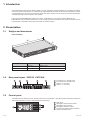
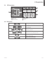
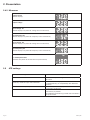
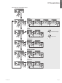
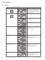
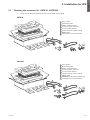
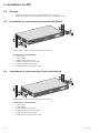
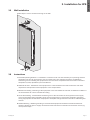
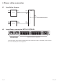
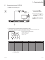
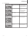
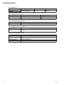
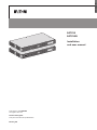
ENGLISH
EATS16
EATS16N
Installation
and user manual
Copyright © 2015 EATON
All rights reserved.
Service and support:
Call your local service representative
EATS16_EN
SAFETY INSTRUCTIONS
SAVE THESE INSTRUCTIONS. This manual contains important instructions
that should be followed during installation and maintenance of the ATS.
The EATON ATS models that are covered in this manual are intended for installation
in an environment within 0°C to 40°C (32°F to 104°F) and free of conductive contaminant.
Certification standards
•
•
•
•
•
-
-
Safety: IEC 62310-1
EMC: IEC 62310-2
Performance: IEC 62310-3
CE Mark
Additional conformances :
IEC 60950-1
CISPR 22 Class B
Important safety notes
•
•
-
-
•
•
•
•
•
•
•
•
Only qualified personnel can service this equipment.
Follow the following precautions when working on this unit.
Remove watches, rings, or other metal objects.
Use tools with insulated handles.
Examine the packing container. Notify the carrier immediately if any damage is present.
Do not disassemble the unit.
Do not operate the unit near water or in an area with excessive humidity.
Keep liquid and foreign objects from getting inside the unit.
Do not operate the unit close to gas or fire.
Verify whether the branch circuit breaker or fuse on service feed is correct.
Verify line voltage requirements and the supplied line voltage prior to installation.
This unit is supplied from multiple sources, disconnect all sources before servicing.
Electrical warnings
• Check that power cords, plugs, and outlets are in good condition.
• RAL equipment: "Equipment intended for installation in Restricted Access Location".
Warning
• Intended to be connected to computer load.
• Not to be connected to inductive load or with >3:1 crest factor load.
Page 2
EATS16_EN
1. Introduction........................................................................................ 4
2. Presentation....................................................................................... 4
2.1 Weights and dimensions................................................................................................4
2.2. Rear panel layout - EATS16 - EATS16N...........................................................................4
2.3 Control panel...................................................................................................................4
2.4 LCD description..............................................................................................................5
2.4.1 Power flow......................................................................................................................5
2.4.2 Measures........................................................................................................................6
2.5 ATS settings....................................................................................................................6
2.6 Warning...........................................................................................................................8
3. Installation for ATS............................................................................ 9
3.1 Checking the accessory kit - EATS16 - EATS16N............................................................9
3.2 Storage......................................................................................................................... 10
3.3 Installation for rack mounting (normal installation)....................................................... 10
3.4 Installation for rack mounting (2 post installation)........................................................ 10
3.5 Wall installation............................................................................................................. 10
3.5Instructions .................................................................................................................. 11
4. Power cables connection................................................................ 12
4.1 Installation diagram....................................................................................................... 12
4.2 Input/Output connection EATS16 - EATS16N............................................................... 12
5. Communication............................................................................... 13
5.1 Communication ports: EATS16N.................................................................................. 13
5.2 Eaton Intelligent Power Software suite........................................................................ 14
6. Maintenance.................................................................................... 15
6.1 Troubleshooting............................................................................................................ 15
7. Specifications................................................................................... 16
EATS16_EN
Page 3
ENGLISH
Contents
1. Introduction
The EATON Automatic Transfer Switch (ATS) is a high availability switch designed for providing redundant
power for sensitive equipment. It is powered by two independent power sources and automatically makes
a rapid switch from one source to the other when the power supply used to power its connected load fails.
This ATS is designed to be efficient and reliable.
Users can know EATON ATS’s power flow, status, parameters from the LCD interface. Besides, the
EATS16N unit has a network interface for users to read and write parameters. The network interface can be
implemented via the Ethernet protocol through an RJ45 connector.
2. Presentation
2.1
Weights and dimensions
Rack installation
W
D
H
Description
Weights
(kg / lb)
3.32 / 7.31
3.54 / 7.8
EATS16
EATS16N
Dimensions H x W x D
(mm / inch)
43 x 438 x 250 / 1.7 x 17.24 x 9.84
43 x 438 x 250 / 1.7 x 17.24 x 9.84
2.2. Rear panel layout - EATS16 - EATS16N
1
2
3
3
4
1
2
3
4
Input Source 1: IEC C20 inlet
Input Source 2: IEC C20 inlet
Output: 8 x C13 10 A
Output: 1 x C19 16 A
2.3 Control panel
The ATS has three buttons on the control panel and a LCD display. It provides useful information about the
ATS itself, load status, events, measurements and settings.
1 LCD panel
2 Navigation: Scroll down button
2
3 Navigation: Enter button
5
1
3
4 Navigation: Escape button
5 Transfer Test: Scroll down and Enter
4
buttons pressed for 5s
Page 4
EATS16_EN
2.4 LCD description
4
3
1
2
1
Power flow
3
ATS Settings
2
Measures/Infos
4
Events
2.4.1 Power flow
or
or
S1 powered but not powering the load
or
S2 powered but not powering the load
or
or
or
EATS16_EN
is defined as the priority source (true by default)
S1
or
S2
S1
or
S2
S1
or
S2
or
is defined as the priority source (can be set)
not powered
not powered
powering the load
powering the load
Transfer
or
Transfer
Transfer
or
Transfer
from S1 to S2
from S2 to S1
from S1 to S2 for Test
from S2 to S1 for Test
Page 5
ENGLISH
2. Presentation
2. Presentation
2.4.2 Measures
Output current
(default display)
Output voltage
Input voltage : S1
(default display only when S1 voltage is out of tolerance)
Input frequency: S1
(default display only when S1 frequency is out of tolerance)
Input voltage : S2
(default display only when S2 voltage is out of tolerance)
Input frequency: S2
(default display only when S2 frequency is out of tolerance)
S1 and S2 phase shift
(available only when S1 and S2 are not synchronized)
2.5 ATS settings
OUTPUT: Sets voltage thresholds
ALARM: Silents alarm
SENSITIVITY (mainly for LIA UPS): Sets
Sensitivity mode for input mains detection.
P SOURCE: Sets the priority source
TRANSFER:
Page 6
200 V - 208 V - 220 V - 230 V (default) - 240 V
ON: normal beep in warning or fault mode, by default
OFF: silent.
Std: Normal Sensitivity, by default
Lo: Low Sensitivity, for compatibility with distorted
waveform.
Sc.1: Priority on Source 1, by default
Sc.2: Priority on Source 2
Std: no additional break even if S1 and S2 are not
synchronized, by default
Gap: additional break during transfer if S1 and S2 are
not synchronized.
EATS16_EN
Press Enter to reach settings menu
OUTPUT
ALARM
To cancel the changes
To select value
SENSITIVITY
PRIORITY SOURCE
TRANSFER
EATS16_EN
Page 7
ENGLISH
2. Presentation
2. Presentation
2.6 Warning
For Fault, refer to troubleshooting section 6.1.
Event
Example of displays
Rootcause
Overload
Load is over nominal rating
Remove some of the equipment from
the ATS. The ATS continues to operate,
but may shutdown if the load increases.
The alarm resets when the condition
becomes inactive.
Unsynchronized sources
One source N and L are reversed
S1 ansd S2 are fed by different phase
(L1/L2/L3)
S1 and S2 frequency are different
Page 8
Source 1 or Source 2 power loss
One of the source is missing,
The ATS power on the load with the
source that is present.
Source 1 or Source 2 voltage out
of tolerance
One of the source voltage is out of
tolerance.
The display shows the voltage measure
of the faulty source.
Source 1 or Source 2 frequency
out of tolerance
One of the source frequency is out of
tolerance.
The display shows the frequency
measure of the faulty source.
Source 1 and Source 2 quality
The sources are outside ranges so that
it generates too many transfers within a
short period of time.
The alarm resets when the condition
becomes inactive.
EATS16_EN
3.1 Checking the accessory kit - EATS16 - EATS16N
•
Verify that the following additional items are included with the ATS:
EATS16
1
2
3
4
5
6
7
8
User manual
Quick start guide
Safety manual printed
2 x Input cables: C19-C20
2 x Input cable lockers
Plastic strips for output locking
RS232 cable
Accessories for rack installation
4
7
3
8
2
1
6
5
EATS16N
1
2
3
4
5
6
7
8
9
User manual
Quick start guide
Safety manual printed
2 x Input cables: C19-C20
2 x Input cable lockers
Plastic strips for output locking
RS232 cable
DB9/RJ45 serial cable for NMC card
Accessories for rack installation
4
7
3
9
2
1
5
8
6
EATS16_EN
Page 9
ENGLISH
3. Installation for ATS
3. Installation for ATS
3.2 Storage
• Please store the ATS in its original package and in a dry place.
Keep the storage temperature between -13 to 131°F (-25°C and +55°C).
3.3
Installation for rack mounting (normal installation)
2
1
3
2
1
3
Follow steps 1 to 3 for module mounting on the rails.
Accessories for rack installation
• 1 x Ear (Left)
• 1 x Ear (Right)
• 4 x M4 x 6 flat screw for ear
• 4 x M6 x 10 cage nut clip for rack4
• 4 x M6 x 12 flat screw for rack
• 4 x M6 washer conical plate for rack
3.4
Installation for rack mounting (2 post installation)
2
1
3
2
1
3
Follow steps 1 to 3 for module mounting on the rails.
Accessories for rack installation
• 1 x Ear (Left)
• 1 x Ear (Right)
• 4 x M4 x 6 flat screw for ear
• 4 x M6 x 10 cage nut clip for rack4
• 4 x M6 x 12 flat screw for rack
• 4 x M6 washer conical plate for rack
Page 10
EATS16_EN
3.5
Wall installation
Follow steps 1 to 2 for module mounting on the wall.
1
2
2
1
3.6Instructions
1. Elevated Operating Ambient - If installed in a closed or multi-unit rack assembly, the operating ambient
temperature of the rack environment may be greater than room ambient. Therefore, consideration
should be given to installing the equipment in an environment compatible with the maximum ambient
temperature (Tmax) specified by the manufacturer.
2. Reduced Air Flow - Installation of the equipment in a rack should be such that the amount of air flow
required for safe operation of the equipment is not compromised.
3. Mechanical Loading - Mounting of the equipment in the rack should be such that a hazardous condition is
not achieved due to uneven mechanical loading.
4. Circuit Overloading - Consideration should be given to the connection of the equipment to the supply
circuit and the effect that overloading of the circuits might have on overcurrent protection and supply
wiring. Appropriate consideration of equipment nameplate ratings should be used when addressing this
concern.
5. Reliable Earthing - Reliable grounding of rack-mounted equipment should be maintained. Particular
attention should be given to supply connections other than direct connections to the branch circuit (e.g.
use of power strips).
EATS16_EN
Page 11
ENGLISH
3. Installation for ATS
4. Power cables connection
4.1 Installation diagram
UPS
Input
UPS 1
UPS
Output
ATS
Input
ATS
S1
ATS
Output
to the sensitive equiment
UPS
Input
UPS 2
UPS
Output
ATS
Input
S2
4.2 Input/Output connection EATS16 - EATS16N
Inputs connections
from UPSs outputs
Ouput connection to equipment
1. Connect input power cables to UPSs output and to ATS inputs (S1 is the default priority source).
2. Connect ATS output to the equipment.
Page 12
EATS16_EN
5.1
Communication ports: EATS16N
• RS232 communication port
1. Connect the RS232 2
communication cable to
the serial on the computer.
2
2. Connect the other end of the
communication cable 2 to the
RS232 1 communication port
on the ATS.
The ATS can now communicate
with EATON power management
software.
• Characteristics of the optocouplers communication port
When a signal is activated, the contact is closed between the common (Pin 4) and the pin of the
corresponding signal for n.o contact, and vice versa for n.c contact.
common
5
4
9
Pin assignment
Pin 1
Pin 2
Pin 3
Pin 4
Pin 5
Pin 6
Pin 7
Pin 8
Pin 9
EATS16_EN
3
8
2
7
1
6
Contact characteristics (optocoupler)
• Voltage: 48 V DC max
• Current: 25 mA max
• Power: 1.2 W
Description
Summary alarm signal
RX
TX
Common
GND
Source 1 OK
Source 2 OK
Load on source 1
Load on source 2
Contact type
n.o
n.c
n.c
n.c
n.c
Open State
Normal
Source 1 is failure
Source 2 is failure
Source 1 not take load
Source 2 not take load
Close State
Alarm occurred
Source 1 is ok
Source 2 is ok
Source 1 takes load
Source 2 takes load
n.o: normally opened
n.c: normally closed
Page 13
ENGLISH
5. Communication
5. Communication
• Connectivity Cards: EATS16N
Connectivity cards allow the ATS to communicate in a variety of networking environments and with
different types of devices. The Network-MS card has SNMP and HTTP capabilities as well as monitoring
through a Web browser interface; connects to Ethernet network. In addition, an Environmental Monitoring
Probe can be attached to obtain humidity, temperature, smoke alarm, and security information.
ETHERNET
100M
10M
Setting/Sensor
UPS data
Reset
Network-MS card
5.2 Eaton Intelligent Power Software suite
Eaton Software suite provides up-to-date graphics of ATS power and system data and power flow.
It also gives you a complete record of critical power events, and it notifies you of important ATS or power
information.
Page 14
EATS16_EN
6.1 Troubleshooting
Operation status
Overload
Possible cause
Power requirement exceeds the
ATS capacity (greater than 105 % of
nominal).
Action
Remove some of the equipment
from the ATS.The ATS continues
to operate, but may shutdown
if the load increases.The alarm
resets when the condition becomes
inactive.
Short-circuit fault
A short-circuit occurred.
Check device connection or
integrity.
If error persists, note the alarm
message and the ATS serial
number, and then contact your
service representative.
EATS16_EN
Internal relay fault
Internal relay fault, note that the
load is no powered.
Note the alarm message and the
ATS serial number, and then contact
your service representative.
Source 1 or Source 2 power
supply fault
Internal power supply of one of the
source is faulty; the other source is
powering the load.
Note the alarm message and the
ATS serial number, and then contact
your service representative.
EEPROM fault
EEPROM fault, note that the load is
still powered.
Note the alarm message and the
ATS serial number, and then contact
your service representative.
Page 15
ENGLISH
6. Maintenance
7. Specifications
Table 1. Model list
Model
EATS16
EATS16N
Operating voltage
Current rating
Operating frequency
200/208/220/230/240 Vac 1ɸ 16A
50/60 Hz
Table 2. Weights and dimensions
Model
EATS16
Dimensions H x W x D (mm/inch)
43 x 438 x 250 /1.7 x 17.24 x 9.84 Weight (kg/lb)
3.32 / 7.31
EATS16N
43 x 438 x 250 / 1.7 x 17.24 x 9.84
3.54 / 7.8
Table 3. Electrical input connections
Model
Input connection
EATS16 - EATS16N
IEC C20 inlet (2 x Input cables: C19-C20 provided)
Table 4. Electrical output connections
Model
Output connection
EATS16 - EATS16N
1 x C19
8 x C13
Table 5. Environmental and safety
Operating temperature
Storage temperature
Relative humidity
Operating altitude
Audible noise
Page 16
0°C to 40°C (32°F to 104°F)
-25°C to 55°C / -13°F to 131°F
Storage: 0-90%
Operating: 20-85%
2000m meters (6252 ft)
25 dBA max (without buzzer)
EATS16_EN