
1
Workplace Planner Help
© 2013 Proplanner
2
1
Proplanner Work Place Planner
Proplanner Work Place Planner
Help Version 3.6
Copyright Proplanner 2013
© 2013 Proplanner
3
2
Introduction
Workplace Planner allows you to:
Determine cycle times in a workplace (operator walking and stationary or moving parts)
Compute processing times from predetermined time systems
Perform Lean value-added and Ergonomics assessments
Generate animations for the workplace, which allows for validation of the analysis and can
enhance communication
There are two versions of Workplace Planner available, a stand-alone version and an add-on to
AutoCAD. The stand-alone version incorporates an AutoCAD engine inside the application.
This allows you to use Workplace Planner even if you do not have a copy of AutoCAD.
Workplace Planner's AutoCAD engine does not have all the features of a full AutoCAD license;
it is more similar to an AutoCAD LT license.
For users that do have the AutoCAD program (AutoCAD, ADT or Mechanical Desktop), the
Workplace Planner add-on links to the license and enhances the program with Workplace
Planner's capabilities.
You will not be able to operate Workplace Planner fully without a licence file; you will be
restricted to evaluation mode and unable to use more than one routing file. Please see the next
section for licensing instructions.
© 2013 Proplanner
4
3
Introduction
Licensing
To use Workplace Planner, you have two different options. You will see a screen similar to the
one below when you open Workplace Planner.
Start free trial usage
If you would like to try Workplace Planner, select this option to begin a 30-day trial period
for full-feature evaluation. A status bar will appear when you open Workplace Planner to indicate
how many days remain on your trial license.
Activate by email
To activate and register your copy of Workplace Planner by email, you may select this
option and you will see the window similar to the one below. Fill in your Company name, then
click the Copy Info button. Then click on [email protected] to start an email message
and paste the info into the message. A Proplanner representative will determine if you're eligible
for an extended or permanent license file, and will respond with further instructions.
© 2013 Proplanner
5
If you have any issues or questions in regards to obtaining a license for Workplace Planner,
please contact [email protected].
4
4.1
Getting Started
Preparing and Loading the Drawing
WPP can work in either Engineering (Foot-Inch) or Decimal (Metric) units. By default, the
application will assume that if your drawing is set to Engineering units (Done with the Units
command in AutoCAD) that your base unit is 1 inch in size. If your drawing is set to Decimal
units, then Proplanner will assume that your base drawing unit is 1 millimeter. Once the WPP is
running, you can reset your default base units (to Inches, Millimeters or Meters) in the Licensing/
Settings tab if the selected default is incorrect.
AutoCAD Note: Remember that if you use the AutoCAD UNITS command to change your drawing units, you will
lik ely need to set your drawing limits (size) by using the AutoCAD LIMITS command. You will then need to follow
the limits command with the ZOOM ALL command in order to ensure that you are viewing the entire work area.
Since WPP reads the distance from your drawing, it is important that the drawing is created in
actual size. This means that if the distance between a table and a box is 3’6” in the real world
then the drawing needs to be created such that the table is 42 base units from the box (in footinch units of course).
The drawing does not need to be highly detailed for WPP to work. Essentially, the drawing
needs to contain enough detail so that the WPP user can determine where locations specified in
the operator routing would be located within the workplace.
4.2
Preparing the Routing
The workplace routings can be defined in another application (such as MS Excel) and imported
into WPP, or the routings can be defined within the WPP application. If you wish to create your
© 2013 Proplanner
6
Getting Started
routing file in MS Excel, it is best to first import the stationary or moving.csv files into Excel and
modify them in an effort to ensure that the file format is correct. Documentation on the format of
each field in this file can be found in the appendix of this manual.
You may define a workplace routing within WPP by adding and Inserting lines within the routing
editor. Make certain to use unique element numbers for each row, and to use the proper element
code for a row (W for walking routes and P or M for process times, etc). Also do not forget to
specify a location in the From field for all processing rows in order to tell WPP where the
processing is to occur.
4.3
Conducting the Analysis
Now that your drawing is drawn to actual scale and your routing has been created, you are ready
to select the Calculate command on the main routings window. Calculate will create your
operators for you and will also ensure that all locations (From and To) specified in the routings
are actually located within your drawing. If any routing locations are missing, WPP will prompt
you to locate those within the drawing. Once all locations have been specified, WPP will update
the walk times and distances in the routing editor and will compute the summary distance, time
and lean information in the results window and on the LEAN and Ergonomics Charts.
Selecting the “Save As” button will save your results out to a file. The input routing data and
output results data are stored in the same file. This file is a simple comma-delimited text file that
is easy to import into a word processor or spreadsheet.
© 2013 Proplanner
Conducting the Analysis
5
Reference Section
Routings Tab
Locations Tab
Paths Tab
Stations Tab
Operators Tab
Parts Tab
Animate Tab
Lean Tab
Ergonomics Tab
Reports Tab
Sequencing Tab
Licensing/Settings Tab
© 2013 Proplanner
7
8
5.1
Reference Section
Routings Tab
The routings tab is the main window of the WPP interface. In this window, you can Import, Save,
and Calculate your studies, as well as enter and edit part routings and processes. Each route
(also referred to as an element) identifies a move or process activity for an operator. These
routes need to be defined in the order in which they occur for each operator. There is no
required order for routes between operators. For example, it would not matter if you alternated
the routes for Operator1 and Operator2 versus first specifying all Operator1 routes and then
Operator2 routes (the only exception occurring with Synchronized operators, discussed in the
following paragraphs).
Special Note: Your analysis summary will appear in the lower left corner of the routings screen. You
may right-click in this window to copy these results to the clipboard. In fact, you can right-click and
copy all WPP display list window information for subsequent pasting into other windows applications,
such as MS Word or MS Excel.
Main Controls
Route Format
Parsing Options for User-P (MOST) and MODAPTS
Parsing Options for user-defined User-K1 and User-K2
Synchronized Operators
Moving Part Cycles
Workplace Planner with Proplanner
© 2013 Proplanner
Routings Tab
5.1.1
9
Main Controls
File Open: Loads the routing file into the routing editor. The import control will also set the Calc
Stationary/Moving Part option, and read the drawing for location text, walk paths, and part paths
and fill their associated displays.
New (Clear): Clears the current routings list, so that new routings may be entered.
Save As: Saves the routings in the editor to a file, along with the units of the study and any
results in the lower-left results window.
Goto AutoCAD: Hides the WPP Modal window and displays a smaller Modeless editing
window. This command is used when you need to work in the AutoCAD editor environment but
wish to return to the WPP application and retain your information. The Modeless window (shown
below) will appear in the far upper-left corner of the AutoCAD window. The controls included
within this modeless window are discussed in their respective sections (i.e. Locations, Paths,
etc.)
Modeless Window displayed after clicking Goto AutoCAD
Calculate: The calculate button performs the distance and time calculations and generates and
updates the flow paths.
Calculate first looks in the drawing to see that all of the referenced locations exist. If some
locations that appear in the routing, do not appear in the drawing, then WPP will prompt the user
to enter each location. In this case, the user will be prompted to select the calculate button again
to resume the calculate procedure once all of the input locations have been specified.
Calculate also computes the trace information needed for the Animation, and thus calculate
must be run prior to viewing the Animation.
Stationary Part or Moving Part: Determines which calculate method to use. For
example, if a file containing relative part locations (i.e. @L5) would be calculated with
Stationary Part option, then WPP will prompt the user for the location @L5 which will be
referred to thereafter as a fixed location. Likewise, calculating a Stationary routing file
with the Moving Part option will actually work the same as if it were calculated with the
Stationary option.
© 2013 Proplanner
10
Reference Section
Flow on Part: This checkbox is available for selection when the Moving Part option is
chosen. By default, this option is selected on, which means that WPP will add flow
distances for the operator when they are working on the moving part (and thus moving
with the part). Checking this option off will tell WPP to ignore reporting walk distances for
the worker when traveling with the part (i.e. riding the conveyor). Obviously, the total
operator times will be reported identically in either situation.
Part Sequence (cycle): This button selects which single cycle or all to show results and lean
values for.
Percentage: Chooses the value by which to calculate the walk, lean, and delay percentages.
Each Operator – Uses the actual cycle time computed for each operator.
Longest – Takes the longest cycle time of the operators in the results window and sets
this as the cycle time for each operator. Internal delay time is then added for the operators with
the shorter cycle times.
TAKT Time – Allows the user to specify a line TAKT time and then sets this as each
operator’s individual cycle time. Note that the TAKT time needs to be larger than any of the
operator cycle times.
Loc&Path Selection: Determines if flow paths, part paths, locations, labels and arrows are to
be evaluated and modified for the entire drawing (in the case of one workplace per drawing) or
for a selected window area within the drawing.
All Locs Option: the All Locs option allows WPP to use reference locations outside of the
windows selection area (only applicable if window-area is selected).
Routing Editor Controls
Insert Row: Inserts a row above the selected row and copies the information from the input
boxes below the routing display into this new row as a default starting point.
Remove Row: Removes the selected row.
Add Row: Takes the data in the input boxes below the routing display and adds them to the end
of the routing file.
Update Row: Takes the data in the input boxes below the routing display and updates them to
the selected routing in that display.
Up or Down : Moves the selected row, up or down one row.
Description (shown below): Is where the general description and those for the left and right
hand processes are stored.
The up arrow to the right of the text field can be clicked to open a new description window. In the
case of some time standards, such as MTM-B, MTM-UAS or MOST, and non-predetermined
time, it is optional to put the process description in the description field if it involves more than
one statement. In this situation(MTM), it is necessary to put the word DESC, /DESC or DESC/
© 2013 Proplanner
Routings Tab
11
DESC in the Process field of the routing to direct the parser to look for codes in the left hand,
right hand or left and right hand description fields respectively.
Upon selecting the carrot next to the description field, the user can input both right and left hand
descriptions as seen below.
Results Window in lower left of Routings tab
Oper: Operator for which the results are shown.
Dist: Distance being traveled for entire process.
Time: Total time of operations or time of each cycle.
Walk% : Percent of total time spent walking.
VA% : Value-added percent.
NVABN% : Non-value-added but necessary.
NV% : Non-value-added percent
ID% : Internal Delay is time spent waiting on a machine or synchronized operator.
XD% : External Delay is time spent waiting on a part to reach the station.
© 2013 Proplanner
12
Reference Section
5.1.2
Route Format
EL# - Element Number, used to synchronize specific element routings (rows) in WPP
with other applications – such as Proplanner. If you are having the WPP compute
distances for Walk and Hand oriented processes which you wish to re-import back to
Proplanner, or other applications, it is recommended that you not modify these numbers
for existing routings. Proplanner will automatically insert an asterisk “*” for all new
routings.
Type – Element Type
NOTE: When defining your process elements, your entire routing file must use
EITHER "P/M/W-type" or "I-type" elements. Do not combine a routing file with
both types of elements.
EITHER
P or M or T or X – Manual or Automated process element. The WPP will attempt to
parse the text in the Process field upon Calc if a parser type has been selected. The P,
M and T types are for different processes (machine dependent, operator dependent,
etc) as specified by MTM standards. The X element tells the program to ignore the
parsing of the process code for that element line.
W – Walk move, tells WPP to compute the walk distance in Feet or Meters. The WPP
will also parse this element and attempt to use the computed distance in the
computation of time for that element code upon Calc if a parser type has been selected
and if text is entered into the Process Field. [A walk type code is optional for W type
elements]
OR
I – Integrated Walk to, and Process at, element, tells WPP to compute the walk
distance in Feet or Meters (from the operator’s previous location to this new location
specified in the From field) and then apply the process time (at this location) as
specified in the process field. With the Integrated element type, you do not specify the
process time in the Time field (as you do with the M,P,T or X element type). Instead,
you specify your time in the Process field, according to the rules for specifying time in
this field (discussed in the process section below).
A - Activity Header (Not Fully Implemented). This provides for the future opportunity to
define elements within an activity and have the individual element times be
automatically aggregated into the Activity time. The WPP application will only evaluate
the Element rows, and then update the Activity row with the aggregated time values.
H – Hand move, tells WPP to compute the distance in inches (if output Feet) or
millimeters (if output Meters) and replace for distance in hand move code (such as
Reach or Move in MTM-1). The WPP will attempt to parse the text in the Process field
upon Calc if a parser type has been selected. This feature is not yet implemented.
S- Synchronized Move indicates that this task (Walk or Process) cannot begin until all
© 2013 Proplanner
Routings Tab
13
of the operators who are being synchronized have completed their last task prior to the
Synchronized element. To use synchronized moves, you must select a row in the
routing file that is after all routes and processes that must be performed prior to the
synchronized activity for all operators being synchronized. You then create a row
with the element type “S” for synchronous and put the names of the operators that you
are synchronizing in the following fields (Operator, Process, From and To). As such,
there is a maximum possible of 4 operators that can be synchronized. For more
information, please reference the “Synchronized Operators” section of this document.
C – New Cycle, is used only for moving part studies in order to set the arrival of the next
part. After this line, all relative locations are referenced from this new part and thus the
prior part is ignored from this line forward. Cycles can optionally have names (i.e.
2CAR shown below) and start times. Start times can be specified in absolute time with
a time entry such as 40 (for 40 seconds from the beginning of the first part entering the
WPP session) or in relative time @40 (for 40 seconds from the beginning of the prior
part entering the WPP session). For more information, please reference the “Moving
Part Cycles” section of this document.
Symbol – Operation process symbols used to add another degree of detail and
recognizability to route data in the reporting outputs.
Oper - Operator Name. Unique operator names will appear in the Operator tab. You can
add new operators by simply typing in a new operator name in the routings editor. This
new operator will immediate appear as a valid operator within the Operator’s tab.
Process – Process Code to be parsed (if parsing method selected). Otherwise, this text
is just a notation for the user as to the activity being performed, and is not required to be
specified. (reference exception for “I” element types discussed below) The text in this field
will be passed to other programs that may parse the time code, provided that parsing is
not selected within the WPP. Putting the text DESC in this field (upper or lower case) will
tell the parser to look in that element’s Left Hand Description field for the codes to parse.
A DESC/DESC could be specified to tell the parser to look in the Left and Right hand
description fields for both the left and right hand codes respectively. Finally, a DESC/
M2P2 would also be valid to tell the parser to look in the left hand description field for the
left hand code and to use the codes specified in the process field for the right hand (i.e.
© 2013 Proplanner
14
Reference Section
M2P2 which is a MODAPTS code for this example). For additional information on
parsing options refer to the “Parsing Options” section of this document
If the element type “I”, for Integrated, is selected, then the WPP will parse this field to get
the process time, even if no parsing method is selected. In this situation, you need to
enter a time for the processing activity. This time can be specified as a number (in
decimal minutes or seconds as selected in the Options tab). Optionally, you may also
specify a walk time component and a machining time component. If a walk and machine
time is specified, the WPP will ignore the walk time, and will add the machine time to the
manual process time. The syntax for specifying process times in this field is shown below
(shown with time unit set to seconds)
Manual time/[walk time]/[machine time]
(general form)
3.4
(specifies manual 3.4 seconds)
3.4/2.5
(specifies manual 3.4 sec and walk of 2.5)
3.5/2.5/4.2
(specifies manual 3.4 sec, walk of 2.4, machine of 4.2)
3.5//4.2
(specifies manual 3.4 sec, machine of 4.2)
//4.2
(specifies machine time of 4.2 seconds)
To or at Loc – To Location for walkpath analysis and continuity evaluation
Man/walk/machine Time – Shows the breakdown of times into their manual, walking,
and machine usage times.
Freq – Frequency is the number of times that the process or walk activity is performed
per cycle.
Dist – Move Distance from drawing for Hands (H) or walking (W).
Time – Time in seconds to move or process. Times can also be specified in the hours:
minutes:seconds format as shown in the example below, or in Decimal Minutes
according to the settings in the Options tab.
2:42:12.5 would be 2 hours, 42 minutes and 12.5 seconds
Only times associated with element type W moves are computed if no parser is selected.
In this situation, times are expected to be entered by the user, or contained within the
imported file.
LEAN % – Defines the value added content for the element. For example, walking is
considered to be totally non-value added, while Operating or Assembling is 100% valueadded. Other Processing tasks such as reach, grasp, move, etc, may be partially valueadded, or may include Non Value Added but Necessary content.
LEAN values are whole numbers (integers) specified from 0 to 100 (inclusive), and may
© 2013 Proplanner
Routings Tab
15
optionally include a second part to represent Non Value Added but Necessary content.
The first part (before a slash) represents the Value Added content, and the second part
(after a slash) represents the Non Value Added but Necessary content. The slash is
optional if there is no Non Value Added but Necessary content. The following examples
represent valid syntax for LEAN values.
100
100/0
50/20
/40
0/40
is 100% Value Added
is 100% Value Added (slash and zero at end is optional)
is 50% Value Added and 20% Non Value Added but Necessary
is 40% Non Value Added but Necessary
is 40% Non Value Added but Necessary (0 before slash is optional)
For I-type elements, the LEAN value percentage only applies to the process time
component of the integrated element, as the walk time for the I-type element is always
assumed by the WPP to be non-value added. For example, if an I-type element had a
process time of 12 seconds and a walk time of 5 seconds and if the LEAN percentage
was specified as 50 (i.e. 50%) then the WPP would consider the entire element to have 6
seconds of Value Added work content and 11 seconds of Non-Value added work
content.
Weight – Currently a weight is entered into this field for use by the Ergonomics Evaluator.
Weight can be entered as an integer number for walking (Type W) to be used in the
Carry Assessment and also with a posture and integer weight value for Lifting in a
process element. For example, a lift from the floor to the waist for a 10 lb object would be
represented as F10. In addition, a combo-approach can be used if lifting between two or
three zones as shown in the following examples. (FK10 is a lift from the Floor to the
Shoulder for a 10lb object) (FH10 is a lift from the Floor to above the Head for a 10 lb
object)
F – Lift from Floor to Knuckle height when standing
K - Lift from Knuckle height (just below waist) to shoulder height)
H - Lift over Head from shoulder to above
SC – Special Codes field used for process time parsing. Some time estimation
languages, such as MTM-1 and 4M require the addition of Special Codes that are used
to define attributes of the element such as field of vision, In-Motion and Simultaneous
Activities. Currently the MODAPTS and User-P (Most) parsers will assume simultaneous
Left and Right hand motion unless an “L” (must be capital) is put in the SC field, in which
the program will add both the left and right hand times.
© 2013 Proplanner
16
5.1.3
Reference Section
Parsing Options for Used-P (MOST) and MODAPTS
The MOST and MODAPTS predetermined work measurement systems are parameter based
systems in which the parameter values (numbers) following the parameter codes (letters) are
simply added together in order to determine the appropriate number of TMUs or MODs that
define a particular activity. These TMUs, or MODs, are then multiplied by a fractional seconds
value (shown below) in order to determine time in seconds (or Decimal minutes as specified in
the Options tab).
MODAPTS Conversion: 1 MOD = 0.129 Seconds
MTM/MOST (User-P) Conversion: 1 TMU = 0.036 Seconds
For example, a Move and Place task would be defined in MODAPTS as an M2P2 which would
evaluate to 4 MODS and thus 0.516 Seconds. For more information on the MODAPTS and
MOST language syntax, please contact the user manuals produced by their appropriate
organizations.
The WPP application includes special capabilities for parsing these parameter based codes.
These capabilities are described below.
Left and Right Hand tasks with High or Low skill level
Left and right hand codes can be specified by simply separating the codes by a slash character
/. The parser will use the longest processing time of the left or right and thus assumes a High
skill level by default. You may also optionally place a capital H in the SC field to signify High skill
level. If the task is of low skill level and thus the left and right hand codes should be added
together (thus these tasks are performed sequentially) then a capital L should be placed in the
SC field to signify Low skill level.
Partial Code Repetition
Part of the code syntax can be repeated by placing the codes to be repeated in parentheses
that are prefixed by a multiplication factor. For example, in MODAPTS an M2P2 5(W5) would
cause the parser to compute 29 MODs where the W5 parameter number would be multiplied by
5. Likewise, in MODAPTS, a 3(M2P2) would evaluate to 12.
Simultaneous Motions
Part of the code syntax can be ignored by placing the codes to be ignored in angle brackets (i.
e. <>). In some situations you may wish to document a set of simultaneously occurring tasks, but
have the parser ignore some of these tasks which can be performed concurrently. For example,
if the operator was doing a Move and Place task while walking and the walking should be
ignored, then the code should be specified as M2P2 <W5>.
Direct Time Specification for “I” type elements
As mentioned in the discussion for I-type elements, the process time must be specified in the
process field. This can be done by specifying a parse method and including the codes for that
particular method in this field, or it can be accomplished by specifying the time directly as a
direct value as per the format shown below. This format for specifying the process time can be
used if no parse method is selected, or if any parse method is selected – even though the
© 2013 Proplanner
Routings Tab
following format is not valid for that parse method.
Manual time/[walk time]/[machine time]
(general form)
3.4
(specifies manual 3.4 seconds)
3.4/2.5
(specifies manual 3.4 sec and walk of 2.5)
3.5/2.5/4.2
(specifies manual 3.4 sec, walk of 2.4, machine of 4.2)
3.5//4.2
(specifies manual 3.4 sec, machine of 4.2)
//4.2
(specifies machine time of 4.2 seconds)
© 2013 Proplanner
17
18
Reference Section
5.1.4
Parsing Options for user-defined User-K1 and User-K2
The WPP application allows you to define your own user-defined keyword-based parsing
method. To define your own time standard file, simply create a comma delimited text file (CSV)
of the format shown below - following the time code definitions. The first line of this file must
contain the 3-letter code for the units of the times specified in the following file. Unit types and
their 3-letter codes are shown below.
MIN
SEC
TMU
(decimal minutes)
(decimal seconds)
(MTM Association TMU’s which equal 0.036 seconds)
MUS
MOD
(MTM Association MU’s which equal 0.0036 seconds)
(MODAPTS Association MOD’s which equal 0.129 seconds)
The sample code file has it’s fields separated by commas (not shown below).
1. The first field contains the code name (any string – cannot include tabs, spaces or
commas
2. The second field contains description of the task represented by the code. This field is
for user-use only as the program does not parse this field.
3. The third field contains the time for the code, in the units specified in the time code field
at the beginning of the file.
4. The fourth field contains the description of the task frequency (i.e. Each, Per Foot, etc.)
This field is for user-use only as the program does not parse this field.
5. The fifth field contains a number 0, 1 or 2. The 0 number means that the time is a
manual operator time, the 1 code means that the time is a machine processing time, and
the 2 code means that the time is for walking.
6. The sixth field contains the percentage of value added work content in this process.
The percentage is represented by an integer number from 0 to 100 (inclusive).
MIN
A01
A02
A03
A04
LWR SHIELD POS. ELECTRODE & STRIKE
ARC
RAISE SHIELD & REMOVE ELECTRODE
REPOS SHRT. GRPS OF WELDS NO RAISE
SHLD
REPOS LONG
0.05EA
0.05EA
E
E
0
0
100
100
0.02EA
0.04EA
E
E
0
0
100
100
© 2013 Proplanner
Routings Tab
5.1.5
19
Synchronized Operators
The WPP application will allow you to synchronize up to 4 concurrent operators within a
workplace. This feature is most often used when you have tasks that must be performed by
more than one operator concurrently, or when an operator cannot begin a particular task until
another operator has completed a prior task.
Operators can be synchronized in stationary and moving part studies. An operator will wait for
another operator at the last specified location that he/she is routed to prior to the task after the
synchronization element. In moving part studies it is possible that an operator might be waiting
on a moving part for another operator and thus this situation should be taken into consideration
when viewing the animation of synchronized operators in moving part studies.
All routes (elements) for synchronized operators must be completed prior to the synchronization
element before the WPP application will continue on to those tasks listed after the
synchronization element. The order of the tasks specified between operators prior to the
synchronization element can be listed alternately or sequentially as shown in the two examples
below.
Alternatively you could to the following (although this is more difficult to read)
In both situations, OPR1, and OPR2 will both wait at location TABLE (although they could just as
easily be waiting at two different locations) until both operators are available. When they are
both available, OPR1 will process at the TABLE and OPR2 will also perform its activity (not
shown in the current display).
© 2013 Proplanner
20
5.1.6
Reference Section
Moving Part Cycles
The WPP application will allow you to define the entry of multiple sequential parts for moving part
calculations (moving part option only). Up to 25 sequential parts can be specified within the
standard WPP application.
A new part entry cycle is specified with the “C” element type and each cycle may be given a
unique name and reference a unique part, defined on the Parts tab to help identify the unique
work content contained within that cycle. If you do not define a cycle as the first element in your
routing, then the WPP application will assume a part cycle with no name that starts at time 0.
The routing lines that follow the start of a part cycle are directed to that part for all locations on
that part. This referencing continues to either the start of the next part cycle or to the end of the
routing file (whichever comes first). Obviously, the routing lines (elements) for each part cycle
can be different. In this way, you could model a part with no options in the first cycle, followed by
a part with many options in the second and third cycles and then back to a no-option part in the
fourth and final cycle.
Operators will begin work on a following cycle after they complete work from a previous cycle.
Thus, an operator that is running over the cycle time on a prior part will begin work late on the
next part, after it may have entered quite a way into the operator’s workstation.
A new part will enter 30 seconds from the beginning of the analysis shown below.
© 2013 Proplanner
Routings Tab
21
Alternatively, you can specify a part’s entry time as 50 seconds relative to a previous part’s entry
such as shown in the example below, by simply prefixing the time with the @ character.
© 2013 Proplanner
22
5.1.7
Reference Section
Workplace Planner with Proplanner
The Proplanner application can export the Elements of an Activity by using the Export option in
the Activity-Time-Calculated tab. These Elements will be exported to a CSV file of the format
required by the WPP application. Likewise, you may import a WPP routing CSV file into the
element list of a Proplanner activity.
In the 2.0 Version of Proplanner (and above) WPP CSV files can be exported from, and also
imported to, Operations within Proplanner. In this situation, each routing line in the WPP
application will correspond to an Activity time and thus only Walking time tasks will actually be
imported back into Proplanner from the WPP application.
For more information on Using the Workplace Planner with Proplanner please consult the
Proplanner User Manual.
© 2013 Proplanner
Routings Tab
5.2
23
Locations Tab
Locations referenced by the WPP are simple text located on a layer called PP_LOCATIONS
within the drawing. Text positions are referenced via their insertion points, which WPP sets at
Bottom-Center when using the Add Location controls. Users adding text to this layer manually
will want to specify the text insertion points accordingly.
Special Feature – Selecting the Location column heading in the display will sort the locations
alphabetically or by X or Y value correspondingly.
Add Location: Will prompt the user to enter a location name and position within the AutoCAD
drawing environment and also adds it to the location display list.
Erase Location: Erases the selected location from the list and in the drawing. If you wish to
erase locations from the drawing, you can select the Goto AutoCAD control on the Routings
tab and use the AutoCAD erase command.
Erase All Locs: Erases all of the locations from the list and in the drawing. If the window option
is selected on the routings tab, then only the locations within that window will be erased.
Erase Temp Locs: Erases all of the temporary locations from the list and in the drawing.
Temporary locations are those automatically created by the WPP application within a moving
part study to mark operator positions at the part along the assembly line. These locations are
automatically erased and regenerated upon every selection of the Calculation command.
© 2013 Proplanner
24
Reference Section
Save Locations (File): Saves the location display to a comma-delimited CSV file in the same
format as shown in the display. Used for exportation of locations to other applications. The
WPP application does not read these files.
Location Text Height/Update: Specifying a new location text height and selecting Update, will
change the size of all text on the PP_LOCATIONS layer.
© 2013 Proplanner
Locations Tab
5.3
25
Paths Tab
The Paths tab is the main control for path editing and annotation.
List Select
Erase Path: Selects (in the drawing) the currently selected path from the path display list, and
then deletes it from the drawing and the path display list. The path will be regenerated
automatically by WPP on the next Calc.
Edit/Redo Path: Selects (in the drawing) the currently selected path from the path display list,
which WPP will automatically delete and then prompt the user to select vertices (up to 11
vertices to create a maximum of 10 segments) for a new path to replace it. User-defined paths
are replaced by Euclidean paths when WPP creates new paths, such as is done in ALL Moving
part studies or when the “All Paths” option is selected on this path window during stationary part
studies.
Erase Listed Paths: Will erase all the walk flow paths shown in the current list, which are paths
in the Drawing referenced by this routing file.
© 2013 Proplanner
26
Reference Section
Drawing Select
Erase Path: Allows the user to select a path in the drawing and then deletes it from the drawing
and the path display list. The path will be regenerated automatically by WPP on the next Calc.
Query Path: Allows the user to select a path in the drawing and display its properties as shown
in the example below.
Edit/Redo Path: Allows the user to select a path in the drawing, which WPP will automatically
delete and then prompt the user to select vertices (up to 11 vertices to create a maximum of 10
segments) for a new path to replace it. User-defined paths are replaced by Euclidean paths
when WPP creates new paths, such as is done in ALL Moving part studies or when the “All
Paths” option is selected on this path window during stationary part studies.
Erase DWG Paths: Will erase all of the walk flow paths in the current drawing regardless of if
they are referenced by this routing file or not.
Path Arrows
Delete: Deletes all arrows.
Update: Any change to the arrow size or placement option will only occur on the next calc or
when this Update button is selected.
Path Arrows checkbox: Determines if paths should have arrows.
Path Ends/Path Vertices: Determines if arrows are to be placed at path ends only, or also at
each path vertex.
Arrow Width/Arrow Length: Specifies the size of the arrow for a zero width path. As the path
is scaled larger by the Path Thickness value and the Path Frequency, the arrows for those
specific paths will be factored accordingly.
Path Labels
Delete: Deletes all labels.
Update: Any change to the label size or placement option will only occur on the next calc or
when this Update button is selected.
© 2013 Proplanner
Paths Tab
27
Path Labels checkbox: Determines if paths should have labels.
Ends Only: Places labels in the middle of the last segment of the path specifying the total
distance of that path. If checked off, then labels are placed at every segment also to show the
length of that segment. In this case, the last segment has two distance labels. The one in
parenthesis is the total path length, and the alternate one is the segment distance.
Above Line/On Line: Determines if labels are placed center on the line or positioned slightly
above the line (i.e. text insertion point Center or Bottom-Center) to the center of the line
segment.
Label Height: Specifies the height of the label.
Precision: Determines how many decimal places to show in the path distance labels.
On-Calc Options
All Paths/Missing Paths: When All Paths is selected, WPP will first erase all existing paths in
the drawing (including manually generated ones) and replace them with new Euclidean (point-topoint) paths. Selecting only Missing Paths (default) will result in WPP only generating paths not
yet existing.
Other
Save Paths (File): Saves the location display to a comma-delimited CSV file in the same
format as shown in the display. Used for exportation of flow path distances to other applications.
The WPP application does not read these files.
© 2013 Proplanner
28
5.4
Reference Section
Stations Tab
The Stations Window is where all the part path information for the individual stations is
accessed within the WPP. The data itself is stored within the part path poly line within the
drawing. NOTE: The information within the "Stations" tab is only used when performing
Moving-Part studies. Users who are performing "Stationary" studies need not enter
any information into this tab.
Station: This input box is where the station names are assigned.
Description: Allows the user to describe the station for future reference.
Start: This is the distance from the beginning of the Part Path line where the station begins.
Length: This is the length of the station, starting at the start distance.
Update: Updates the station list with the new information.
Add: This button adds the station created to the list.
Remove: Removes the selected station from the list of available stations.
Save to Part Path: Saves the station data into the Part Path line on the AutoCAD drawing.
Draw Part Path: Allows the user to draw the path on which the parts will travel. The first point is
considered the start or zero distance. This would be set as 0 if a station was being defined as
starting here.
Import Assignments: Allows for station assignments to be imported as a .csv file.
Container Insert: Can be used to create containers for stations.
© 2013 Proplanner
Stations Tab
5.5
29
Operators Tab
Operators are automatically listed in the Operators display when they are uniquely specified in
the routings file. The WPP will automatically generate their respective flow path layers (as each
operator’s flow is generated on a unique layer PP_FLOW-opname) in which all of the operator
information is stored on the drawing. In addition, the WPP will generate a default Loaded and
Unloaded walk speed from the settings on the Options tab (Default: 4.17 feet/second). The user
is allowed to specify a unique layer color for each operator.
Calc: Allows the user to turn off the calculation of all walkpath flows for the specified operator.
With this option set to off, the walkpaths will not be updated or included in the total walkpath
distance and time calculations, and the operator will not animate.
Delay: The delay time is set to 0 by default. This time allows the user to delay the availability of
the operator within the workplace. A time in seconds may be entered into this field. The
distance option is allowed for moving part analyses so that workers in downstream stations can
begin work when the part travels the specified distance from the beginning of the line to their
station.
Start Location: Determines if, and where, WPP should begin the operator’s movement prior to
assuming the first position specified for that operator in the routing file. A value of NONE
(default) tells the WPP to ignore that operator’s initial location.
Station: Assigns the operator to a station to prevent the operator from trying to reach locations
within other work stations.
Previous Distance/Next Distance: Sets the distance which an operator is allowed to move
© 2013 Proplanner
30
Reference Section
into the previous and next station in order to intercept the part. This calculation does not take into
account the length of the part. if the part is long and at the beginning of the walkpath while the
operator goes to the end of the part, the operator may still walk further into the previous
workstation. This is easily overcome by subtracting the part length from the value entered into
this field or adding an operator delay.
Block Name: Allows the user to represent the operators with any individual blocks inserted in
the drawing before the WPP was opened.
Special Feature – Changing the name of the operator and selecting the update button will
automatically search and replace all occurrences of that operator name in the routings file.
Special Note: Operator names cannot contain any special characters other than dashes and
underscores. (!@#$%^&*) and other non-letter characters are not allowed.
© 2013 Proplanner
Operators Tab
5.6
31
Parts Tab
The Parts tab controls the part and path properties for the Moving Part Calculation. This is where
the part blocks are assigned to the part names referenced in the routings. The part information
is stored in the parts.prt file in the AutoCAD Programs folder with the rest of the Workplace
Planner files. This file name can be changed on the Licensing/Settings tab. NOTE: The
information within the "Parts" tab is only used when performing Moving-Part studies.
Users who are performing "Stationary" studies need not enter any information into this
tab.
Part Info
Open/Save Parts: Allows the user to store or open pre-made part information for different
scenarios.
Part Name: Generic part name linked to the routings and each cycle that uses that part.
Block Name: Name of block which has been assigned to represent the given part name when
the animation is run.
© 2013 Proplanner
32
Reference Section
Blocks are loaded upon startup of the WPP so if the user adds a new block to the drawing,
WPP will need to be restarted before it will read the block in this drawing. Only valid blocks
currently available within the drawing are shown in the pull-down list. Blocks must be defined
with their default direction and insertion point as shown below.
SPECIAL NOTE: Backup and Metric or Standard versions of the default blocks can be found
on the installation CD in the folder called SAMPLE FILES.
Length: Determines the part length for the A, B, C and D longitudinal offset parameters in the
relative part location syntax. (i.e. @L<B references a location in the center of the part 1/3 of the
way back from the front.
Width: Determines the part width for the W offset parameter in the relative part location syntax.
(i.e. @LW references the beginning of the part at the width offset (1/2 width) from the center of
the part’s flow path.
Speed: Determines the speed of the vehicle for animation and Moving Part positional
calculation. Remember that part speed must be less than operator speed (preferably by at least
a factor of 2) or the operators will not be able to “catch” the part.
Draw Part Path: Prompts the user for points that make up a polyline path on the PP_PARTPATH layer. A maximum of 5 segments are allowed for a part path within a workstation. A part
path must be specified before a Moving Part calculation can be performed.
© 2013 Proplanner
Parts Tab
5.7
33
Animate Tab
The animate window sets up the animation speed, precision, and repetitions. This tab also
allows the user to save a trace file that can be used to create an animation in other programs.
Move Increment: Determines the resolution of the animation. Smaller values (minimum of
0.05) will make the animation run more accurately and more slowly and smoothly. Larger values
will provide the opposite effect. As such, the final workstation animation time could be different
than the calculated workstation cycle time - as displayed in the operator results display on the
Routings tab. In this situation, the values in the routings tab are ALWAYS more accurate.
Motion Delay: Allows the operator to slow down the animation by inserting a delay between
each animation move. This delay value will often be needed when viewing animations in 2D with
simple (i.e. default) operator and part blocks.
Save Animation Trace: The Calculation process generates an animation trace events list
which is used by the animation engine to present the results of the calculation to the user. This
trace list can be optionally saved to a file for use in evaluating the animation events textually or
possibly for use by other external animation applications. If other applications are to use this
trace file then it is likely that those applications will also need the location and path coordinate
information stored in the Locations (LOC) and Paths (PTH) files respectively. Together, the
LOC, PTH and TRC files provide all of the information required by any external animation
application to replay the events generated by the WPP application.
The WPP application does not read or use a saved trace file, as this information is automatically
created by the WPP application when the Calculate option is selected from the main routings
© 2013 Proplanner
34
Reference Section
tab.
Automatic Rerun: Causes the animation to automatically rerun until stopped by the user. This
setting is ideal for presentation and demonstration purposes where it is desired for the
animation to run continuously in an unattended mode.
Animate: Selecting this button will switch control to the AutoCAD window and begin the
animation while displaying the animation counter in the Modeless WPP control window. Once
complete, the user will have the option to Return to Walkpath or ReRun the Animation. The
animation can be stopped and started with the Alt key.
Draw Part Path: draw the moving part path. It is used for Moving Part study.
© 2013 Proplanner
Animate Tab
5.8
35
Lean Tab
The LEAN tab charts the percentage of walking, value-added processing, non-value-added
processing, non-value-added-but-necessary processing and internal delay for each operator in
the workplace.
Part Sequence (Cycle): The dropdown window here again lets the user chose which cycle or
all cycles for which to show the lean percentages.
© 2013 Proplanner
36
5.9
Reference Section
Ergonomics Tab
The Ergonomics tab charts the operator safety for the Lift and Carry tasks involving weight and
posture defined within the routings. The WPP uses the “SNOOK” tables developed by Liberty
Mutual Insurance in 1991 and approved by OSHA. The WPP allows the user to compute results
for both 75% Females and 75% Males.
SHIFT LENGTH – The SNOOK tables require a number of cycles (or repetitions) of the routing
performed over a given period of time. The Shift length determines the total duration of time
during which the routing is performed. Together with the Task Focus (defined below), and the
routing cycle time, the WPP is able to determine the number of repetitions per day over the shift
length time to determine the safety of the task.
TASK FOCUS – The task focus defines the percentage of time during the shift that the operator
is performing the activities defined in the routing. For example, if the operator is working an 8
hour shift (as defined in the shift length), but only performs the routing cycle ½ of the time during
this shift, then the Task Focus value would be 50 to represent 50%.
© 2013 Proplanner
Ergonomics Tab
37
5.10 Reports Tab
The Reports tab is where you generate your workstation report. The workstation report includes
an image of your workstation, along with workstation header information that you can enter in the
top right of the screen.
Select the Get Image button to get the current view of your workplace. You may need to select
the Goto AutoCAD button in order to adjust your display such that the workstation view looks
correct. If using a window select, selecting get image a second time may zoom in more
precisely on the section selected.
Once your view is acceptable; select the Station Report button to generate your report. Using the
Value Added Time/Reg. Time option will create the same station report with VA/NVA
percentages and times. Another option is the Man/Machine report to demonstrate the
difference in manual versus machine work times in the same format as the original station report
(note this report is available upon request). Once the report is generated, simply select the File
Save option in the browser window to save your report.
These reports can be set to show both Activities and Elements or either choice separately. This
will help the user gauge how much information is needed to be displayed.
(Note the total time calculated on the Station Report does not include the external delay added
by waiting for the next part, only the actual time spent working on this part.)
© 2013 Proplanner
38
5.11
Reference Section
Sequencing Tab
The Sequencing tab provides functions for importing a ProBalance study of tasks and
generating a Workplace Planner process routing. Once a line balancing xml file is saved from
the Proplanner Line Balance tool, it can be imported into the Workplace Planner on this tab. This
tab then selects the model and options to be simulated within a work station and creates a
routing that can be analyzed, edited, or animated. NOTE: The information within the
"Sequencing" tab is only used when performing Moving-Part studies, where the
processing steps are imported from ProBalance. Users who are performing
"Stationary" studies need not enter any information into this tab.
Open Scenario: Selects the Line Balancing xml file to open for simulation.
Save Scenario: Saves the scenario and any changes made to LB routing data in the WPP.
This option is available only when one model/option mix has been selected.
Open Sequence: Opens a pre-made sequence file that contains numerous model/option
mixes in a given sequence. This can be used to create the routings file once Line Balancing
information has been loaded and a station selected.
Save Sequence: When model/option mixes are added and put into the desired sequence, it
can be saved to a file which can be loaded in the future to avoid recreating the operation
sequence.
Up/Down: Moves selected build up or down in the Build Sequence window.
Insert: Insert’s a row similar to the selected option/model mix above this row. Will use
© 2013 Proplanner
Sequencing Tab
39
information provided in the Sequence Start and Description field instead of the attributes of the
selected build if they are different.
Remove: Erases the option/model mix selected from the Build Sequence window.
Add: Adds Line Balancing data for the selected station and model/option mix to the
sequence that can later be used to create a routing file to run a WPP simulation.
Update: Updates the selected build with the Sequence Start and Description information in the
input fields to the left of this button.
Station: Selects which work station to simulate from the Line Balancing file that will contain all
stations within the plant.
Model: Defines the specific model for which this routings will be made. You can choose
different mixes and add them to the sequence.
Options: Sets the options for which the simulation will be created. You can choose different
mixes and add them to the sequence.
Create Routings: Uses the selected station, model, and options to create the routings file for
activities and operations done within that work station in that scenario. In other words, this
generates the actual simulation routing file.
© 2013 Proplanner
40
5.12
Reference Section
Licensing/Settings Tab
The Licensing/Settings tab is where the licensing codes and expiration dates are set, as well as,
the special options available within the application. The Help button will access the on-line help
document, which is also available as a PDF file (located in the program directory) for easier
print-out. All entries in this tab window are saved between user sessions.
5.12.1 License Codes
When you first run the application you will need to go to the options menu and enter your License
Code. License codes are provided by your Proplanner sales representative, or can also be
obtained by contacting Technical Support. License codes are generated to link the WPP to
your copy of AutoCAD. Therefore you will need to provide the Proplanner representative with
your AutoCAD serial number (shown on the options screen) so that they can generate the
appropriate code for you.
Upon entering the code and selecting the Update License button, the WPP will save this code to
a license file in the WPP application directory specified at installation time.
License Code: This is where you enter the code given to you by the Proplanner representative.
Codes are case sensitive (capital and lower case letters are considered to be different). You
may copy this code from the email sent to you by Proplanner and then paste it in this field.
Expiration: This is where you enter the expiration month and year for the software. For example
if the expiration date is 6/2006, the last day the product will work would be May 31. Purchased
licenses will not have an expiration date and thus this field must be left blank. You must enter the
expiration date EXACTLY as it is given from Proplanner (for example: 9/05 is different than
9/2005). You may copy this code from the email sent to you by Proplanner and then paste it in
© 2013 Proplanner
Licensing/Settings Tab
41
this field.
5.12.2 Process Parsing Options
Process Parsing: Determines if the WPP should attempt to evaluate the Process code column
for the routings and compute the appropriate process times. MTM-B, MODAPTS, User-P
(MOST), and User-K1 or User-K2 (user defined keyword parser) are available in the application
by default. Users may request the MTM-1, MTM-2, MTM-4M and MTM-UAS standards from the
MTM Association, or a Proplanner representative. Remember that Proplanner’s Time
estimation module will also parse these Process codes and can Import and Export files from/to
the WPP. Proplanner can import/export a Workplace Planner study as ELEMENTS of an
ACTIVITY, or as ACTIVITIES of an OPERATION, whereby the walk tasks are assigned as
delays to the ACTIVITY links within the OPERATION. For additional information on parsing
options refer to the “Parsing Options” section of this document. Also, for additional information
on the interface between Proplanner and the Workplace Planner, refer to the “Workplace
Planner with Proplanner” section of this document.
When any of the Keyword-based parse methods (MTM-B, MTM-UAS, MTM-2, User-K1 or UserK2) is chosen, you may select the button just to the right of the Process field (as shown below)
to pull-up the process list. This process list is a view of your process standards file and it lets
you select a particular standard, so that you do not need to type it in.
The standard times in the list will be in the units of the list (i.e. Minutes, Seconds, TMU’s,
MU’s, MOD’s) and will be automatically converted into the current WPP session units
(Minutes or Seconds) upon selection.
If you want to override the process time as specified in your standards file, you can do so
by selecting the Process Type “X”. This will tell the parser to ignore parsing the process
code in that element.
© 2013 Proplanner
42
Reference Section
For those standards that are specified in distance, or per-item, you can use the frequency field
to factor the number of occurrences of the process type within your element line.
Selecting the option to Include Description will copy the standard’s description into the element
description field within the routing editor.
© 2013 Proplanner
Licensing/Settings Tab
43
Use Standard Derived Walk Time: If this option is selected, then the operator speed
(specified in the Operators tab) is ignored and the distance is used to compute the walk time by
using the user-selected predetermined time system (MODAPTS or USER-P).
Increment MODAPTS walk by 5 MODS: If the MODAPTS time parsing is selected, then the
application will automatically round up walk distances in increments of 5 MODS. Even if this
option is not checked, the application will never report a walk time of less than 5 MODS.
Example:
Increment by 5 MODS
Actual
ON
OFF
2.5
5
5
7
10
7
5.12.3 Time Units
Hours:Minutes:Seconds: Allows for the entry (by the user) and output (by the application) for
time in an Hours:Minutes:Seconds format. As such, a time of 91.6 will be automatically
interpreted as 1:31.6 (one minute, thirty one point six seconds).
Hours:Decimal Minutes: Allows for the entry (by the user) and output (by the application) for
time in an Hours:Minutes format. As such, a time of 91.6 will be automatically interpreted as
1:31.6 (one hour, thirty one point six minutes).
5.12.4 Walk Speed Options
The WPP walk speed options give you extensive flexibility in specifying workplace walk time
estimates. Note: these time calculations are bypassed if the user selects the USER
STANDARD DERIVED WALK TIME option AND if the parser is set to the MODAPTS or
USER-P.
Start Walk Time (secs): The time for the first foot or 1/3 meter of walk distance. If this value is
zero, then the WPP will use the operator’s Loaded/Unloaded speed for this initial distance.
Min Dist: The minimum distance for any move. If this value is zero, then the WPP will use a
minimum distance of 1 Inch or 1 millimeter.
Differentiate After: The distance (after the first foot or 1/3 meter) for the WPP to use for the
BEGINNING WALK SPEED, after which the WPP will use either the Loaded or Unloaded
speed. If this value is zero, then the WPP will use the operator’s Loaded/Unloaded speed for
the distance after the first foot or 1/3 meter.
Beginning Walk Speed: The speed used by the WPP for the distance up to and including the
distance specified in the DIFFERENTIATE AFTER FIELD. A value of zero in this field will
cause the WPP to use the operator’s Loaded/Unloaded speed for this initial distance.
Default UnLoaded Walk Speed: The default speed that the WPP will use for walking without a
load when new operators are added by the WPP.
Default Loaded Walk Speed: The default speed that the WPP will use for walking with a load
© 2013 Proplanner
44
Reference Section
when new operators are added by the WPP.
Consider Loaded Above: If the routing element’s weight is GREATER THAN this value, then
the WPP will use the Loaded Speed for that operator, otherwise the WPP will use the Unloaded
speed.
Times in Feet/Second
Example Default
0.72
0 Start Walk Time
3
0 Min Dist
6
0 Differentiate After
2.78
0 Beginning Walk Speed
4.17
5 Default UnLoaded Walk Speed
3.33
4 Default Loaded Walk Speed
5
5 Consider Loaded above
© 2013 Proplanner
Licensing/Settings Tab
45
5.12.5 Moving Part Options
5.12.5.1 Start Position if First Loc on Part
Determines the FROM location when the To/At location for the First element is a relative location
on the part, and/or when the first element’s type is Integrated.
Start at Op Start Location: The WPP will start the operator at that Operator’s START location
as specified in the Operator’s tab.
Start at last Element Location: If the location of the last element is not a relative location on
the part, then the WPP will start the operator at this location and then move to the location
specified in the first element. If the last element’s location is on the part, then the WPP will
default to using the Operator’s Start location as the from location for the first element.
5.12.5.2 Part Grid
1 to ? L/C/R: A number from 1 to N (where n is from 1 to 25) that specifies how many zones are
longitudinally spaced along the part followed by the letter L for Left, R for Right, or C for Center.
A number 7 is the default amount of longitudinal divisions. The first and last zones are directly at
the front and the back of the part respectively.
@2L (specifies a location on the left side at the width and 2/7 back)
@1R (specifies a location on the right side at the front)
@3C (specifies a location at the center and 3/7 back)
© 2013 Proplanner
46
Reference Section
R/L/W A to ?: The method to specify a location on a Moving part. L-Left, R-Right, W-Width and
then a letter from A to Z that specifies how many zones are longitudinally spaced along the part.
The letter D is the default. The first and last zones are directly at the front and the back of the
part respectively. You must always place an ‘At’ symbol (@) at the beginning of this location
name. You may optionally replace the letter ‘W’ with a distance from the center of the part out to
the side (Feet or Meters). You may also optionally replace the longitudinal letters (i.e. A to D)
with a distance from the front of the part to the back. The examples below assume the default of
A to D and units of Feet
@LW<B (specifies a location on the left side at the width and 1/3 back)
@R (specifies a location on the right side at the front)
@RW<2.5 (specifies a location on the right side at the width and 2.5 feet back)
@R1.2<C (specifies a location on the right side 1.2 feet from the center and 2/3 of the way
back)
5.12.6 Other Settings
Output Units: Sets the default distance units for output information from the program.
Base Drawing Units: Sets the default distance units to read distances from the drawing.
Location Text Layer: The layer that the WPP will look to find location text. Default is
PP_LOCATIONS.
Path Thickness: Determines how thick a path should be for each unit of travel frequency
specified in the flow path routing. A value of zero will generate dimensionless thick flow lines.
Path thicknesses are generated during a Calc command.
Automatically Renumber Elements: If this is set, then the program will constantly renumber
your elements sequentially. (NOTE: some applications that you interface with, my require the
element numbers not to be changed in the WPP application.)
Always route last loc to first loc: Automatically route the last location in the element list to the
first location.
© 2013 Proplanner
Licensing/Settings Tab
47
Line Delimiter: This setting allows the user to select either the comma or semi-colon for the
delimiter it uses to separate information in the input files. The default comma separated files are
not always standard for foreign numeric notations that use commas instead of periods.
Automatically Erase Temp Locations: Automatically erase the temporary locations
generated in the drawing.
Parts File Name: The default directory and file for the parts file used in WPP.
Save Settings: Saves the values specified in the Application Settings and Defaults frame so
that they will be default for all subsequent sessions.
© 2013 Proplanner
48
6
Reference Section
Tutorial
There are three tutorials to help you become familiar with Proplanner's Workplace Planner:
These tutorials (both Metric and FootInch versions) are located in subdirectories within the
HELP subdirectory located in the directory where the program was installed (typically c:\program
files\proplanner\autocad programs).
The Metric tutorials (base unit is millimeter) are available in two forms (comma and semi-colon
delimited). The comma delimited metric tutorials are for those countries who use the same
number format as the United States (i.e. 1,200.52), and the semi-colon tutorials are for those
countries (Germany, Italy, France, Sweden, etc.) who reverse the comma and decimal point (i.e.
1.200,52).
Stationary Part Analysis
Moving Part Analysis
Sequencing from Line Balance data
© 2013 Proplanner
49
6.1
Stationary Part Analysis
STEP 1: To get started, make sure all other drawings in AutoCAD are closed. If you have
already been working in Workplace Planner, click the New (Clear) button in the Routings tab.
Then Open the file “WALKPATH-2D.DWG”. You should be able to see the Proplanner
Applications menu on your screen. If not, you will need to load this menu using the Menu
Installation Guide included in the Install.pdf.
STEP 2: Select the “W” icon button in the Proplanner ribbon.
© 2013 Proplanner
50
Tutorial
STEP 3: To import an existing workplace routing file, select the File Open
button from the top right corner of the Routings tab screen as shown below.
Then select the STATIONARY.CSV file provided with the WPP application.
© 2013 Proplanner
Stationary Part Analysis
51
STEP 4: You should now be able to select the Calculate button in the bottom right of the screen
to analyze the initial workplace layout. If it prompts that not all locations are present, add them by
clicking on a location on the drawing. If an error states that a station has no length, go to the
stations tab and update the length to 40'. The results of this Calculate can be seen in the
Distance and Time columns in the right side of the routings window and in the Results Area in
the bottom left corner. In addition, the flow lines should have been drawn in your layout as shown
below. Depending on your version of AutoCAD and the specific tutorial files that were loaded,
the drawing and routings may vary.
© 2013 Proplanner
52
Tutorial
STEP 5: You can now select the Locations tab to see the location text that Proplanner found on
the PP_LOCATIONS layer within the drawing. This text has already been added for you,
however you could add additional location(s) by selecting the Add Location button in the middle
right of this screen, under DWG Select, or by going into AutoCAD and simply placing text
manually on this layer.
STEP 6: You can now select the GotoAutoCAD to see the walk paths that were drawn by
Proplanner in the workplace between the locations. Proplanner automatically generates flow
paths using Euclidean (point-to-point) lines.
© 2013 Proplanner
Stationary Part Analysis
53
STEP 7: Flow paths may be set to move through other objects. In this example, one of the flow
paths currently moves through a table. To replace this straight line flow path with one that moves
around the table select the Edit/Redo Path button in the DWG Select section of the Paths Tab
as shown below.
© 2013 Proplanner
54
Tutorial
STEP 8: The WPP window will now disappear and you will be in the AutoCAD application
window. AutoCAD is prompting you to select a path to replace with a new manually drawn one.
Select the path to be moved as indicated by the white arrow below.
STEP 9: The original path will now disappear and you will be prompted to enter a path from
START to FIXTURE. Simply pick points starting from where the path originated around the table
and then finally to the FIXTURE as shown below. When you pick your last point at the fixture you
can press Enter on the keyboard, or your Right mouse button. A WPP Alert window will show
up. Click “OK”. You will then be returned to the Paths tab in the WPP application.
© 2013 Proplanner
Stationary Part Analysis
55
STEP 10: To evaluate the impact of this change. Simply select the Routings tab at the top and
re-select the Calculate button. Make sure that the study is set to stationary part Calculate in the
bottom right of the routings tab. Your new total walk distance and time will be updated, and your
paths will look like those shown below. If the distances cannot be seen, within the paths tab there
are options to increase arrow width and height, as well as path labels. Clicking update will
change the labels (lengths) automatically to the new height.
STEP 11: Now select the Operators tab to see the operator in your study. This window is filled
when you load, or define, your routings. Every time that you use a unique operator name, it will
appear in this window. From this window, you can set the walking speed of your operators and
the color of their flow paths. An ability to set the maximum distance traveled into the previous
workstation to work on a moving part has also been included here.
© 2013 Proplanner
56
Tutorial
STEP 12: Select the Operators tab and select the Person Block name of “PERSON” or
"PP_PERSON" in the pull-down box shown highlighted below. Next, select the Animate tab to
see the animation options. Finally, select the Animate button at the top of the screen to watch
the operator perform the work in 2D.
© 2013 Proplanner
Stationary Part Analysis
57
As the animation runs, you will see the screen shown below with the animation time displayed
(Note: this time is dependent on your simulation Move Increment value specified in the
Animate tab window and thus may not agree exactly with the final results). Decreasing the
move increment will increase the accuracy of your results and will slow down your animation.
You can also slow down the animation by entering a delay factor in the Motion Delay input box.
STEP 13: Now you are going to add a new route just before the end of our existing routing. To
do this, select the last row in the routing window and press the Insert Row button. Now select
this new row and enter the location name BOX in the To Loc column and then press the Update
Row button.
You have just changed the routing from RACK2 to the FIXTURE to instead go from RACK2 to
the BOX and then to the FIXTURE. At this point you could go to the Locations tab and add the
location BOX, however we are instead just going to let the WPP prompt us for this location when
we select the Calculate button. Your final result should look like that below.
© 2013 Proplanner
58
Tutorial
STEP 14: Select the Calculate button to re-Calculate the workstation cycle time and paths.
Since you added a new location that has not yet been placed in the drawing, the WPP will
display the following window alerting you to this fact. Selecting OK on this window will take you
into the AutoCAD window and allow you to select the position for the missing location.
Now select a position in the drawing for our new BOX in the place shown below.
Moving Locations
To move locations select the Goto AutoCAD button and either use the AutoCAD Stretch
command (crossing window option) or the Move command to relocate the Location text. Using
the Stretch option will also move the end points for the flow paths, whereby the Move option will
not. The user may also just grab the location text and drag it to the new location.
© 2013 Proplanner
Stationary Part Analysis
59
Upon returning to the WPP and selecting Calculate, the flow paths that were stretched will
report their new distances correctly, however the program will not automatically regenerate new
flow paths for the relocated Location text, so those paths will report the same distances that they
had in the prior Calculate. As such, you need to either go to the Paths Tab and delete the paths
that would be affected by the relocated Location text labels, or you need to select the All Paths
on Calc option in this menu and then select the Calculate button (as shown in the example
screen below). Selecting All Paths will tell the WPP to first delete all of the flow paths and then
regenerate them to their current Location text positions. Selecting All Paths is recommended
in situations whereby you do not have many manual paths specified, as those manual paths will
also be deleted by the All Paths option thus requiring the user to re-specify them.
© 2013 Proplanner
60
Tutorial
Step 15: The output abilities of the WPP can be seen in the summary results window in the
bottom left side of the routings window, the Lean chart on the LEAN tab, and the reports created
on the Reports tab.
The Lean chart is automatically created for the stationary example and will have different
amounts of Value and Walking depending on the speeds and distances that are set.
The Station Report can be created on the Reports tab by selecting get image, setting your
stations takt time, and clicking Generate Report. The Station Report output can be exported
directly to Excel, saved, or printed.
Congratulations!! You have now completed the first tutorial on using the Proplanner Workplace
Planner for stationary parts. You may now continue on to the next tutorial on using the WPP for
moving parts, or you may wish to continue on to the WPP Manual.pdf for more detailed
information on the WPP options.
Special Note: Your analysis summary will appear in the lower left corner of the routings screen.
You may right-click in this window to copy these results to the clipboard. In fact, you can rightclick and copy all WPP display list window information for subsequent pasting into other
windows applications, such as MS Word or MS Excel.
© 2013 Proplanner
Stationary Part Analysis
6.2
61
Moving Part Analysis
STEP 1: To get started, make sure all other drawings in AutoCAD are closed. If you have
already been working in Workplace Planner, click the New (Clear) button in the Routings tab.
Then Open the file WALKPATH-FCAD.DWG for Metric tutorials or WPP_Moving.DWG for
FootInch, just as you did in the first Tutorial.
If you are already in AutoCAD you need not leave and reload AutoCAD, however, you will
also need to go to the Routings tab and select the Goto AutoCAD button as shown below.
STEP 2: You should now be in the AutoCAD screen and will be looking at the 2D or 3D static
workplace layout. To view the moving part (dynamic) workplace layout select the view icon, or
type in the VIEW command in the command line, and double-click on the DYNAMIC-2D option
and select OK.
© 2013 Proplanner
62
Tutorial
If your layout drawing looks like the top view of a 3D drawing (solid filled boxes) instead of wireframe outlines, as shown above, then you need to select the 2-D wire-frame view of the layout.
To do this select the 2D Wireframe icon located in the top right corner of the AutoCAD, or within
the view tab dropdown depending on your AutoCAD version. If you could not find the 2D
Wireframe icon, please right click at the blank space on the toolbar, choose from the popup
menu "ACAD => Shade" or "ACAD=>View Style" depending on your AutoCAD version.
STEP 3: Once your view is correct, you will want to go into the WPP application. Depending
upon how you are starting this tutorial do the following
New into AutoCAD: Perform step 2 in the first Tutorial.
From Goto AutoCAD in WPP: Select the Return to Workplace Planner button from
the WPP modeless window located in the top left corner of the screen.
© 2013 Proplanner
Moving Part Analysis
63
STEP 4: Now in the Routings tab select the File Open button at the top right and load the
MOVING.CSV file. Your screen should look like that shown below when you are done.
You will notice that in the lower right of the screen, that your Calculate option was changed from
Stationary part to Moving Part because the application noticed the @ characters at the
beginning of some of your From and To locations.
From a routing file perspective, the only difference between a stationary part and a moving part
analysis is that in a moving part study you need to reference where you want to be on the part
and let the WPP determine where the part is at the time that you wish to go to (or from) it.
In order to specify where you wish to be on the part, you use a simple coding system that is
prefixed with an @ character to specify that the location is a relative one (just like in AutoCAD).
The second character is a number representative of a fraction of the total distance back from the
front of the part followed by an L or an R (uppercase as are all location names).
© 2013 Proplanner
64
Tutorial
The method to specify a location on a Moving part: A number from 1 to N (where n is from
1 to 25) that specifies how many zones are longitudinally spaced along the part followed by the
letter L for Left, R for Right, or C for Center. A number 7 is the default amount of longitudinal
divisions. The first and last zones are directly at the front and the back of the part respectively.
@2L (specifies a location on the left side at the width and 2/7 back)
@1R (specifies a location on the right side at the front)
@3C (specifies a location at the center and 3/7 back)
The actual distances of the width and length offsets are determined by the part size, which is
specified in the Parts tab in the WPP as shown below.
STEP 5: Now that the routing file is loaded, you should ensure that your part dimensions and
part path speeds are correct. The Parts tab shown above is also where the parts are assigned
blocks to be animated with.
For the Foot-Inch example, a part speed of 40 feet/minute and a part length and width of 15’2” (or 182 inches) and 5’-4” (or 64) inches has been used. When entering feet, do not forget to
include the single-quote after the number or the program will assume that your input is being
specified in Inches.
You may also wish to select the Operators tab to verify that the default operator speed is what
you want. The WPP sets Operator walking speeds to 4.17’ per second which is an industry
standard used in MTM time studies. Another option on this tab is to set a max distance that the
operator can travel into a previous station to reach the part. If the part size is too big, the
operator may still go further than the limit so part length should be taken into consideration when
setting this number or the length of the part path.
© 2013 Proplanner
Moving Part Analysis
65
STEP 6: The Calculation is nearly ready to be ran. The only step left is to define the station
dimensions on the Stations tab shown below. Name the station, select what distance on the
part path the station begins, and how long the station is. Hit the add button to add the station or
the update button to save changes and now you’re ready to do a Calculate. In this example, the
correct station information should have be present, if not, enter 40' as the length.
© 2013 Proplanner
66
Tutorial
Now you can return to the Routings tab and simply select the Calculate button at the lower right
of the window. You will see the results shown in the Results Window (lower left of window) and
Drawing - see examples below (actual results will vary slightly from these examples due to
changes in the individual sample files).
You will notice that in this example, you have two different operators and their flow paths are
shown in different colors.
To generate this diagram, the WPP computed the speed of the vehicle, and the speed of the
operator walking. The WPP then took into account the process times at the vehicle and at the
containers and racks along the line. The WPP then computed all of the line part/operator
intersection locations, created labels for these locations along the part path (white text
perpendicular to part path), and generated the flow lines accordingly with path labels and flow
arrows.
STEP 7: Once you have completed the analysis you can select the Parts tab to make sure that
the part block is set to CAR, Operator tab to make sure the operator is set to 3OPSDFEM, and
© 2013 Proplanner
Moving Part Analysis
67
then proceed to the Animate tab to perform the following step.
STEP 8: Now on the Animate tab select the Animate button in the bottom right of the screen
and watch the operators at work. You will notice that when the operators are working on the car,
they travel at the speed of the car, but when the walk around the workplace, they travel at their
walking speeds (which are faster – and must be – than that of the car).
Step 9: Finally, (and once the animation is complete, but before selecting the Return to
WalkPath button) you will need to select the view icon or type in the VIEW command to see the
animation in 3D [if using FCAD DWG]. Now double-click on the DYNAMIC-3D option and
select OK.
© 2013 Proplanner
68
Tutorial
STEP 10: Now select the ReRun Animation button and watch the show! Remember that
selecting the Alt key and reselecting it will start and stop the animation.
STEP 11: After all the calculations have been completed, you can go to the reports window.
The workstation report includes an image of your workstation, along with workstation header
information that you can enter in the top right of the screen. Similarly the Man/Machine report
displays the breakdown of both manual and machine related labor times. These reports can be
set to output Activities and their Elements or either option separately.
© 2013 Proplanner
Moving Part Analysis
69
Select the Get Image button to get the current view of your workplace. You may need to select
the Goto AutoCAD button in order to adjust your display such that the workstation view looks
correct. You can also get image from a window. For best results getting image by a selected
window hit “Get Image” twice.
Once your view is acceptable; select the Station Report button to generate your report. This
report can also be made to show VA/NVA percentages by checking the checkbox. Once the
report is generated, simply select the File Save option in the browser window to save your
report.
© 2013 Proplanner
70
6.3
Tutorial
Stationary Part Analysis Metric
This tutorial was developed with the drawing units set to millimeters and the reporting units set to
meters. In addition, the files have been saved in a semi-colon (;) delimited format with numbers
specified in the format (1.200,15) which is common in France, Germany, Italy, Sweden and other
countries. Before starting the tutorial, it is advised that you go to the "Licensing Settings" tab
and ensure that your settings are set as shown below.
STEP 1: To get started, make sure all other drawings in AutoCAD are closed. If you have
already been working in Workplace Planner, click the New (Clear) button in the Routings tab.
Then Open the file “WALKPATH-2D.DWG” (make certain that you use only the tutorial files from
the metric-semicolon directory). You should be able to see the Proplanner Applications menu
on your screen. If not, you will need to load this menu using the Menu Installation Guide included
in the Install.pdf.
STEP 2: If Workplace Planner is not already open, select the “W” icon button in the Proplanner
ribbon.
STEP 3: To import an existing workplace routing file, select the File Open button from the top
right corner of the Routings tab screen as shown below. Then select the STATIONARY.CSV
file provided with the WPP application.
© 2013 Proplanner
Stationary Part Analysis Metric
© 2013 Proplanner
71
72
Tutorial
STEP 4: You should now be able to select the Calculate button (bottom right of the screen) to
analyze the initial workplace layout. The results of this Calculate can be seen in the Distance
and Time columns in the right side of the routings window and in the Results Area in the bottom
left corner. In addition, the flow lines should have been drawn in your layout as shown below.
© 2013 Proplanner
Stationary Part Analysis Metric
73
STEP 5: You can now select the Locations tab to see the location text that Proplanner found on
the PP_LOCATIONS layer within the drawing. This text has already been added for you,
however you could add additional location(s) by selecting the Add Location button in the middle
right of this screen, under DWG Select, or by going into AutoCAD and simply placing text
manually on this layer.
STEP 6: You can now select the GotoAutoCAD to see the walk paths that were drawn by
Proplanner in the workplace between the locations. Proplanner automatically generates flow
paths using Euclidean (point-to-point) lines.
© 2013 Proplanner
74
Tutorial
STEP 7: One of the flow paths currently moves through a table. To replace this straight line flow
path with one that moves around the table select the Edit/Redo Path button in the DWG Select
section of the Paths Tab (shown below in red oval).
© 2013 Proplanner
Stationary Part Analysis Metric
75
STEP 8: The WPP window will now disappear and you will be in the AutoCAD application
window. AutoCAD is prompting you to select a path to replace with a new manually drawn one.
Select the path in the top middle as indicated by the white arrow below.
© 2013 Proplanner
76
Tutorial
STEP 9: The original path will now disappear and you will be prompted to enter a path from
START to FIXTURE. Simply pick points starting from where the path originated around the table
and then finally to the FIXTURE as shown below. When you pick your last point at the fixture you
can press Enter on the keyboard, or your Right mouse button. A WPP Alert window will show
up. Click “OK”. You will then be returned to the Paths tab in the WPP application.
You can do this again for the line from TBAR2 to the FIXTURE. When complete, you drawing
should now look as shown below.
© 2013 Proplanner
Stationary Part Analysis Metric
77
STEP 10: To evaluate the impact of this change. Simply select the Routings tab at the top and
re-select the Calculate button. Make sure that the study is set to stationary part Calculate in the
bottom right of the routings tab. Your new total walk distance and time will be updated, and your
paths will look like those shown below.
STEP 11: Now select the Operators tab to see the operator in your study. This window is filled
when you load, or define, your routings. Every time that you use a unique operator name, it will
appear in this window. From this window, you can set the walking speed of your operators and
the color of their flow paths. An ability to set the maximum distance traveled into the previous
workstation to work on a moving part has also been included here.
© 2013 Proplanner
78
Tutorial
STEP 12: Select the Operators tab and select the Person Block name of “PERSON” in the pulldown box (shown above). Next, select the Animate tab, and set the animation options (see
below). Finally select the Animate button in the bottom right corner to watch the operator
perform the work in 2D.
When the animation finishes, you will see the screen shown below with the total animation time
displayed (Note: this time is dependent on your simulation Move Increment value specified in
the Animate tab window and thus may not agree exactly with the final results). Decreasing the
move increment will increase the accuracy of your results and will slow down your animation.
You can also slow down the animation by entering a delay factor in the Motion Delay input box.
© 2013 Proplanner
Stationary Part Analysis Metric
79
STEP 13: Now you are going to add a new route just before the end of our existing routing. To
do this, select the last row in the routing window (Element 18) and press the Insert Row button.
Now select this new row and enter the location name BOX in the To Loc column and then press
the Update button.
You have just changed the routing from RACK2 to the FIXTURE to instead go from RACK2 to
the BOX and then to the FIXTURE. At this point you could go to the Locations tab and add the
location BOX, however we are instead just going to let the WPP prompt us for this location when
we select the Calculate button. Your final result should look like that below.
© 2013 Proplanner
80
Tutorial
STEP 14: Select the Calculate button to re-Calculate the workstation cycle time and paths.
Since you added a new location that has not yet been placed in the drawing, the WPP will
display the following window alerting you to this fact. Selecting OK on this window will take you
into the AutoCAD window and allow you to select the position for the missing location.
Now select a position in the drawing for our new BOX in the place shown below.
Moving Locations
To move locations select the Goto AutoCAD button and either use the AutoCAD Stretch
command (crossing window option) or the Move command to relocate the Location text. Using
the Stretch option will also move the end points for the flow paths, whereby the Move option will
not. The user may also just grab the location text and drag it to the new location.
© 2013 Proplanner
Stationary Part Analysis Metric
81
Upon returning to the WPP and selecting Calculate, the flow paths that were stretched will
report their new distances correctly, however the program will not automatically regenerate new
flow paths for the relocated Location text, so those paths will report the same distances that they
had in the prior Calculate. As such, you need to either go to the Paths Tab and delete the paths
that would be affected by the relocated Location text labels, or you need to select the All Paths
on Calc option in this menu and then select the Calculate button (as shown in the example
screen below). Selecting All Paths will tell the WPP to first delete all of the flow paths and then
regenerate them to their current Location text positions. Selecting All Paths is recommended
in situations whereby you do not have many manual paths specified, as those manual paths will
also be deleted by the All Paths option thus requiring the user to re-specify them.
© 2013 Proplanner
82
Tutorial
Step 15: The output abilities of the WPP can be seen in the summary results window in the
bottom left side of the routings window, the Lean chart on the LEAN tab, and the reports created
on the Reports tab.
The Lean chart is automatically created for the stationary example should look similar to that
below.
The Station Report can be created on the Reports tab by selecting get image, setting your
stations takt time, and hitting Generate Report. The Station Report output can be exported
directly to Excel, saved, or printed.
Congratulations!! You have now completed the first tutorial on using the Proplanner Workplace
Planner for stationary parts. You may now continue on to the next tutorial on using the WPP for
moving parts, or you may wish to continue on to the WPP Manual.pdf for more detailed
information on the WPP options.
Special Note: Your analysis summary will appear in the lower left corner of the routings screen.
You may right-click in this window to copy these results to the clipboard. In fact, you can rightclick and copy all WPP display list window information for subsequent pasting into other
windows applications, such as MS Word or MS Excel.
© 2013 Proplanner
Stationary Part Analysis Metric
6.4
83
Moving Part Analysis Metric
This tutorial was developed with the drawing units set to millimeters and the reporting units set to
meters. In addition, the files have been saved in a semi-colon (;) delimited format with numbers
specified in the format (1.200,15) which is common in France, Germany, Italy, Sweden and other
countries. Before starting the tutorial, it is advised that you go to the "Licensing Settings" tab
and ensure that your settings are set as shown below.
© 2013 Proplanner
84
Tutorial
STEP 1: To get started, make sure all other drawings in AutoCAD are closed. If you have
already been working in Workplace Planner, click the New (Clear) button in the Routings tab.
Then Open the file WALKPATH-FCAD.DWG, just as you did in the first Tutorial.
If you are already in AutoCAD you need not leave and reload AutoCAD, however, you will
need to go to the Routings tab and select the Goto AutoCAD button as shown below.
STEP 2: You should now be in the AutoCAD screen and will be looking at the 2D or 3D static
workplace layout. To view the moving part (dynamic) workplace layout select the view icon, or
type in the VIEW command just as you did in Step 15 of the first tutorial, and double-click on the
DYNAMIC-2D option and select OK.
© 2013 Proplanner
Moving Part Analysis Metric
85
If your layout drawing looks like the top view of a 3D drawing (solid filled boxes) instead of wireframe outlines, as shown above, then you need to select the 2-D wire-frame view of the layout.
To do this select the 2D Wireframe icon located in the top right corner of the AutoCAD window
as shown below (If you could not find the 2D Wireframe icon, please right click at the blank
space on the toolbar, choose from the popup menu "ACAD => Shade" or "ACAD=>View Style"
depending on your AutoCAD version).
STEP 3: Once your view is correct, you will want to go into the WPP application. Depending
upon how you are starting this tutorial do the following
New into AutoCAD: Perform steps 2, 3 and 4 in the first Tutorial.
From Goto AutoCAD in WPP: Select the Return to Walkplace Planner button from
the WPP modeless window located in the top left corner of the screen.
© 2013 Proplanner
86
Tutorial
STEP 4: Now in the Routings tab select the File Open button at the top right and load the
MOVING.CSV file. Your screen should look like that shown below when you are done.
You will notice that in the lower right of the screen, that your Calculate option was changed from
Stationary part to Moving Part because the application noticed the @ characters at the
beginning of some of your From and To locations.
From a routing file perspective, the only difference between a stationary part and a moving part
analysis is that in a moving part study you need to reference where you want to be on the part
and let the WPP determine where the part is at the time that you wish to go to (or from) it.
In order to specify where you wish to be on the part, you use a simple coding system that is
prefixed with an @ character to specify that the location is a relative one (just like in AutoCAD).
The second character is a number representative of a fraction of the total distance back from the
front of the part followed by an L or an R (uppercase as are all location names).
© 2013 Proplanner
Moving Part Analysis Metric
87
The method to specify a location on a Moving part: A number from 1 to N (where n is from
1 to 25) that specifies how many zones are longitudinally spaced along the part followed by the
letter L for Left, R for Right, or C for Center. A number 7 is the default amount of longitudinal
divisions. The first and last zones are directly at the front and the back of the part respectively.
@2L (specifies a location on the left side at the width and 2/7 back)
@1R (specifies a location on the right side at the front)
@3C (specifies a location at the center and 3/7 back)
The actual distances of the width and length offsets are determined by the part size, which is
specified in the Parts tab in the WPP as shown below.
STEP 5: Now that the routing file is loaded, you should ensure that your part dimensions and
part path speeds are correct. The Parts tab shown above is also where the parts are assigned
blocks to be animated with.
For the Foot-Inch example, a part speed of 12,2 meters/minute and a part length and width of
4,6 meters and 1,6 meters has been used.
© 2013 Proplanner
88
Tutorial
You may also wish to select the Operators tab to verify that the default operator speed is what
you want. The WPP sets Operator walking speeds to 1,5 meters per second. Another option on
this tab is to set a max distance that the operator can travel into a previous station to reach the
part. If the part size is too big, the operator may still go further than the limit so part length should
be taken into consideration when setting this number or the length of the part path.
© 2013 Proplanner
Moving Part Analysis Metric
89
STEP 6: The Calculation is nearly ready to be ran. The only step left is to define the station
dimensions on the Stations tab shown below. Name the station, select what distance on the
part path the station begins, and how long the station is. Hit the add button to add the station and
now you’re ready to do a Calculate. In this example, the correct station information has already
been input.
© 2013 Proplanner
90
Tutorial
Now you can return to the Routings tab and simply select the Calculate button at the lower right
of the window. You will see the results shown in the Results Window (lower left of window) and
Drawing - see examples below (actual results will vary slightly from these examples due to
changes in the individual sample files).
You will notice that in this example, you have two different operators and their flow paths are
shown in different colors.
To generate this diagram, the WPP computed the speed of the vehicle, and the speed of the
operator walking. The WPP then took into account the process times at the vehicle and at the
containers and racks along the line. The WPP then computed all of the line part/operator
intersection locations, created labels for these locations along the part path (white text
© 2013 Proplanner
Moving Part Analysis Metric
91
perpendicular to part path), and generated the flow lines accordingly with path labels and flow
arrows.
STEP 7: Once you have completed the analysis you can select the Parts tab to make sure that
the part block is set to CAR, Operator tab to make sure the operator is set to PERSON, and
then proceed to the Animate tab to perform the following step.
STEP 8: Now on the Animate tab select the Animate button in the bottom right of the screen
and watch the operators at work. You will notice that when the operators are working on the car,
they travel at the speed of the car, but when the walk around the workplace, they travel at their
walking speeds (which are faster – and must be – than that of the car). For optimal animation,
you will want to set your animation move increment to 0,1 seconds.
Step 9: Finally, (and once the animation is complete, but before selecting the Return to
WalkPath button) you will need to select the view icon or type in the VIEW command to see the
animation in 3D [if using FCAD DWG]. Now double-click on the DYNAMIC-3D option and
select OK.
© 2013 Proplanner
92
Tutorial
STEP 10: Now select the ReRun Animation button and watch the show! Remember that
selecting the Alt key and reselecting it will start and stop the animation.
STEP 11: After all the calculations have been completed, you can go to the reports window.
The workstation report includes an image of your workstation, along with workstation header
information that you can enter in the top right of the screen. Similarly the Man/Machine report
displays the breakdown of both manual and machine related labor times. These reports can be
set to output Activities and their Elements or either option separately.
Select the Get Image button to get the current view of your workplace. You may need to select
© 2013 Proplanner
Moving Part Analysis Metric
93
the Goto AutoCAD button in order to adjust your display such that the workstation view looks
correct. You can also get image from a window. For best results getting image by a selected
window hit “Get Image” twice.
Once your view is acceptable; select the Station Report button to generate your report. This
report can also be made to show VA/NVA percentages by checking the checkbox. Once the
report is generated, simply select the File Save option in the browser window to save your
report.
© 2013 Proplanner
94
6.5
Tutorial
Sequencing from Line Balance data Metric
This tutorial was developed with the drawing units set to millimeters and the reporting units set to
meters. In addition, the files have been saved in a semi-colon (;) delimited format with numbers
specified in the format (1.200,15) which is common in France, Germany, Italy, Sweden and other
countries. Before starting the tutorial, it is advised that you go to the "Licensing Settings" tab
and ensure that your settings are set as shown below.
STEP 1: Now that you have learned how to run a part study from a pre-constructed routing file it
is time to create one from data that has been output from Proplanner Line Balance. The first
step is to open the drawing file “Multi-Station Moving.dwg”. You will notice that this example has
multiple stations and parts.
STEP 2: Start the Workplace Planner by clicking on the “W” in the menu bar and clicking
anywhere on the splash screen that pops up. This will take you to the routings tab, the main
interface of the WPP.
STEP 3: Click on the “Sequencing” tab to start importing the Line Balance data and select
“Open Scenario”.
STEP 4: Open the pre-made Line Balance scenario file “LBData.xml”. This can be found in the
same directory as the other example files, usually in “c:\Program Files\Proplanner\AutoCAD
Programs”. For more information on making the Line Balance input file with Proplanner Line
Balance, sold separately, consult the Line Balance user manual.
© 2013 Proplanner
Sequencing from Line Balance data Metric
95
STEP 5: To begin with we will start by manually creating a build sequence. The first step of this
is setting up the build information. The first build’s information should be a start time of 0, model
should be set to M1, and the part name CAR. Click the “Add” button. This step is where options
would be selected as well; however this line balance data does not contain option information.
STEP 6: To create a second build, set the start time to a relative time sixty seconds after the
first build’s start with “@60”. Again use model M1 and to use a different part select “CAR2”.
Click “Add” again.
STEP 7: Next select the stations for which you wish to simulate. For this example select station
ST_01L, ST_01R, ST_02L, and ST_02R. Your screen should look similar to below.
STEP 8: Click “Create Routings” and Yes when it asks you if you’re sure. You will then be taken
to the Routings tab automatically where the routings will have been created for the two cycles
using two different parts in four work locations.
© 2013 Proplanner
96
Tutorial
STEP 9: Chose the Operators tab to make sure that your four operators have been created.
Assign each operator to the station with their same name. They will be assigned to station Stat1
and Stat2 at first. This is done by selecting the operator you wish to edit, selecting the station
pull-down menu, selecting the appropriate station and then selecting the “Update” button. When
completed it should look like the example below.
© 2013 Proplanner
Sequencing from Line Balance data Metric
97
STEP 10: Go to the Stations tab and make sure that the stations used are defined correctly.
The ST_01L and ST_01R stations should start at the 0 distance along the part path and have a
distance of 12,2 meters. The ST_02L and ST_02R stations should have a start at the 12,2
meter and be an additional 12,2 meters long. Because the input is in millimeters, this will be in
put as 12.200. Your Station information should look like that below.
Because stat1 and stat2 were unassigned from the operators remove them at this point.
© 2013 Proplanner
98
Tutorial
STEP 11: The only information left to be checked is on the Parts tab. Make sure that CAR and
CAR2 are going at 12,2 M/min. You can also assign a different block to CAR2 at this point by
selecting CAR2 and in the Block Name pull-down menu selecting “police” and hitting “Update”, a
different vehicle will be animated to represent that part.
STEP 12: The final step is to go to the Routings tab, select “Moving Part” as calculation method,
and hit Calculate for the routings that you have created. The output should look like this, and you
will notice that when you animate, two different vehicles are animated representing the two
cycles of work.
© 2013 Proplanner
Sequencing from Line Balance data Metric
99
STEP 13: Returning to the Workplace Planner and selecting the Sequencing tab again will allow
you to save the created build sequence or upload a pre-existing one. Selecting “Open
Sequence” will allow you to open LBData_Seq.xml which is the same as the sequence you just
simulated. If you create routings and Calculate, the results should be the same.
STEP 14: To see the results Calculated there are three main places for this. First of all the
rough summary output can be seen in the bottom left side of the routings tab shown below. The
results are boxed in red.
The blue box highlights the pull down window that selects which cycle to show results for, whether
all or individual part cycles. Below that are radio buttons that select how the output percentages
are Calculated. This can be set to be a percentage of the longest operator’s time, each
individual operator’s time, or as a percentage of a set TAKT time.
© 2013 Proplanner
100
Tutorial
The second output tool of the WPP is the LEAN tab which automatically creates a bar chart
depicting the percentages of time performing value added, non-value added, non-value added
but necessary, and delay times. This can be representative of all the cycles or an individual
cycle, selected in the pull down window and should look like that below for the sequencing
tutorial.
The final and most comprehensive output is the report generated on the Reports tab. These are
generated by selecting get image to take a picture of the current screen, setting a station takt
time, selecting which cycle or all to show results for and pushing the Generate Report button.
Selecting a sequence to report for is done in the pull down window. The report generated should
look similar to the one below.
© 2013 Proplanner
Sequencing from Line Balance data Metric
7
101
Exercise
Plant wide material flow analysis
The objective of this exercise will be to use the techniques learned in the Tutorial, along with the
aid of the How To Guide and Sample WPP Input (in Proplanner fold \Help
Files\PPWPP_Exercise_Samples), to take a simple set of workplace and operator data and perform
a complete Workplace Planner analysis.
Exercise One: Format a data set for importing to the Workplace Planner
Use this Excel spreadsheet (in Proplanner fold \Help Files\PPWPP_Exercise_Samples\WPP1.xls) of
station and operator data along with the Sample WPP Input to create a CSV file to import into
the WPP.
1. To do this extract the data and format it similar to the sample input.
2. Include only the necessary information outlined in the sample input file. It will need picked out of
the original spreadsheet and re-organized.
3. Make sure there are no special characters in the CSV data by opening it in notepad. Also
remove any superfluous commas at the end of the element lines. The Sample WPP Input has
more details on this. Most common errors include spaces and quotation marks.
4. Once the data is set up correctly open the WPP within AutoCAD and try opening the CSV. If
done correctly the files will open flawlessly.
5. If the files cause an error, consult your instructor or the Troubleshooting Guide.
Results – Workplace Planner will open the files with no errors.
Exercise Two: Prepare layout drawing
1. Open “in Proplanner fold \Help Files\PPWPP_Exercise_Samples\WPP_Stationary_1.dwg” in
AutoCAD. You may note that there is a person block placed in the drawing. Leave this there for
use when animating if you chose to do so at a later time.
2. Create layer PP_LOCATIONS by opening the WPP.
3. Insert the names of the locations using the Workplace Planner’s Add Location command. The
location names can be found in the CSV file.
4. Once this is done, open “in Proplanner fold \Help Files\PPWPP_Exercise_Samples\WPP2.csv” to
run a stationary part calculation.
Results – Workplace Planner will not ask user to place locations when a calculation is run.
© 2013 Proplanner
102
Exercise
Exercise Three: Perform a Stationary Part study
Using “in Proplanner fold \Help Files\PPWPP_Exercise_Samples\WPP_Stationary_2.dwg” instead of
the drawing file just created, along with “in Proplanner fold \Help
Files\PPWPP_Exercise_Samples\WPP2.csv” will ensure that we get the same results when this
exercise is complete.
1. Open the drawing and notice that all the locations have been placed as in exercise two. You
may note that there is a person block placed in the drawing. Leave this there for use when
animating if you chose to do so at a later time.
2. Start the Workplace Planner and open the CSV mentioned above. It should be identical, for the
most part, to the CSV file created in the first exercise.
3. Check the Routings tab to make sure all the data has been imported into the correct fields.
4. Go to the Licensing/Settings tab to ensure that the units are in feet and inches and that the
operator start location is set to Operator Start.
5. Return to the Routings tab and select the Stationary Part Calculation radio button. If this option
is set to moving, the calculation will not complete because that method needs a path for the
part to move on.
6. Run the calculation. A Stationary part study will now be drawn on the AutoCAD drawing.
7. Now that the calculation is complete, return to the Routings tab and look at the Results Window
in the lower left side of the WPP window.
Results – The results window should equal those below if the calculation has been run correctly.
Exercise Four: Perform a Moving Part study
1. Open the drawing “in Proplanner fold \Help Files\PPWPP_Exercise_Samples\WPP_Moving.dwg”.
You may note that there is a person and car block placed in the drawing. Leave this there for
use when animating if you chose to do so at a later time.
2. Start the Workplace Planner and open the CSV “in Proplanner fold \Help
© 2013 Proplanner
103
Files\PPWPP_Exercise_Samples\WPP3.csv”.
3. Check the Routings tab to make sure all the data has been imported into the correct fields.
4. Go to the Options tab to ensure that the units are in feet and inches and that the operator
start location is set to Operator Start instead of first or last activity location.
5. On the Licensing/Settings tab set the part speed to 5 feet per minute.
6. Use the Draw Part Path button to go to AutoCAD and draw a horizontal line connecting the
middle of both vertical cell boundary lines, similar to the moving example in the Tutorial.
7. On the Operators tab assign the two operators their respective start locations of START_L and
START_R.
8. Make sure they are assigned to station “stat1” on the operators tab and that the station
“stat1” is defined with the start of 0 and length of 480” or 40’.
9. Return to the Routings tab and select the Moving Part Calculation radio button. If this option is
set to stationary, the calculation will ask for all the on part or moving locations as static
locations.
10.Run the calculation. A Moving part study will now be drawn on the AutoCAD drawing.
11.Now that the calculation is complete, return to the Routings tab and look at the Results
Window in the lower left side of the WPP window.
Results – The results window should equal those below if the calculation has been run correctly.
Exercise Five: Improving layout to reduce labor times
There are many different ways to improve our layouts. For now we will use the drawing, “in
Proplanner fold \Help Files\PPWPP_Exercise_Samples\WPP_Stationary_3.dwg” and “in Proplanner
fold \Help Files\PPWPP_Exercise_Samples\ WPP2.csv” so that we have a common set of output.
The most obvious ways of improving a layout may be to push locations closer together. Because in
many cases there are locations which cannot be moved, we assumed the racks and tables to be
the only mobile locations. To move the locations simply grab the text for the location and drag it
to the new desired locations.
1. Open the drawing in AutoCAD and CSV within the WPP.
2. Notice that the racks have been moved to reduce walk time and increase free space.
© 2013 Proplanner
104
Exercise
3. Run a Stationary calculation to see the results.
Results – You should see results similar to below. Notice the drop in time and walk percentage.
© 2013 Proplanner
105
8
Troubleshoot
Symptom
1. WPP will not start up.
Possible Causes
Solution
Previous version was not
uninstalled before this
installation.
Uninstall by going to Add/
Remove Programs in the
control panel, selecting
Proplanner AutoCAD
Programs and selecting
remove. When done, install
from the disk.
If using the stand-alone
version that comes with
AutoCAD included,
“Supplemental” Install was
not performed.
This setup file can be found
on the install disk in a folder
titled “Supplemental”
Microsoft .NET version 1.1
may not be installed on your
computer.
There is a folder titled
“Microsoft .NET Install” on the
install disk. The setup file is
called “dotnetfx.exe”
If using an older version of
our software, this folder may
not be there. In that case,
this file can be downloaded
and automatically installed by
going to Windows Update
which can most commonly be
reached by clicking a link in
the Control Panel or by going
to Microsoft.com.
The menu bar was not
installed.
For the 2002 to 2005
versions of AutoCAD, Go to
Tools\VBA Manager and load
MENULOAD.dvb. Go to
Tools\Macros and run the
addtoolbar macro.
For the 2006 or higher
versions of AutoCAD or
AutoCAD Engine, type
"cuiload" in the command
line, then load "PP.cui" from
proplanner install fold.
More detailed steps can be
found in the Install guide on
the Proplanner AutoCAD
Programs disk.
2. .csv file does not open.
Excel by default saved the file
as a tab-delimited .csv or an .
xls instead of a commadelimited .csv.
In Excel, select “Save As” and
choose .csv (commadelimited) from the “Save As
Type” pull down menu.
Note that there is also an
© 2013 Proplanner
106
Troubleshoot
option to save as .csv(tabdelimited). This is sometimes
the default .csv setting within
Excel and is what causes this
problem most ofen.
An extra comma has been
placed in the document,
making the program think
there is an extra column of
information.
Open the file in Excel and do
a “Find and Replace” or
“ctrl + h”. Replace the comma
symbol with nothing.
3. Workplace Planner will only License code and or
open the Moving and
expiration date has not been
Stationary examples.
entered.
Go to the Options/Help tab
and enter the license code
exactly as it was emailed to
you. It is case sensitive. Also
enter the expiration date in
the same way, if applicable.
The best way is to just copy
and paste it from the email
you received from Proplanner.
4. License code is rejected.
License code or expiration
date is not typed correctly.
Enter the license code exactly
as it was emailed to you. It is
case sensitive. Also enter the
expiration date in the same
way, if applicable. The best
way is to just copy and paste
it from the email you received
from Proplanner. Make sure
there are no extra spaces in
the input box before you
paste.
5. Distances and times are
drastically incorrect.
Proplanner units differ from
drawing units.
Go to the “Options/Help” tab
and select the appropriate
units, “feet, inches, meters,
and millimeters”. If you do
not know the drawing units,
go to AutoCAD and type
“UNITS” into the command
line. This will bring up a
window where you can get or
enter the desired units.
6. No paths, reports, or
output information is shown.
Calculation has not been
performed since new
information has been added.
All this information is stored
on the drawing or in the input
files once the calculation is
run, but this is not
automatically created until
the first calculation is run or
any time there is a change in
information.
Hit “Calculate” on the
routings tab before
generating the reports or
checking the Paths tab.
7. Reports are showing no
information or format is being
distorted when opened.
Operator is using old version
of Internet Explorer with
which some of the reporting
functions are not compatible.
Go to Windows Update, for
which a link is usually located
in the Control Panel under
Settings and update to the
latest version.
© 2013 Proplanner
107
8. When moving part
calculation is run it asks for
the “on part” locations as
fixed locations.
Analysis type is set to
Stationary Part.
Change the radio button on
the Routings tab to Moving
Part.
9. Part locations do not work
correctly.
There are now two syntaxes
for entering the part location.
The wrong one being
selected will cause an error.
On the Options/Help tab
make sure that the part grid
format is set to the r/l/w or l/
c/r, whichever is the format
the routings follow. Also the
number of spots on the part
is now default of 7 and set to
letters up to D. This can be
changed to the desired
amount of divisions in the pull
down window to the right of
the Part Grid box.
10. Path lines are either too
small or too large.
These do not automatically
scale so must be set
manually.
These can be set manually on
the Routings tab under Path
Thickness/Frequency. This
thickness is scaled in the
drawing units.
11. Despite the operator
This is due to the length of
being limited to a set
the part/path.
distance it can go into the
previous station, it still walks
further than that to reach the
back of the moving part.
This can be overcome by
adding a delay to the process
to let the part enter the work
zone or shortening the part
path so that the worker does
not start working on it until
the entire part has moved
within the work zone.
12. Simulation sends worker
to other stations or to the
origin when doing a moving
part study.
There are duplicate part
paths or locations in the
drawing often caused by
drawings with multiple
stations.
Select by Window Area on
the Routings tab and put a
box around the workstation
the study is focusing on.
13. Frequency, line, and
arrow thickness are
increasing every time a
calculation is performed.
Operator name contains an
improper character.
Operator names are only
allowed to have letters,
numbers, dashes, and
underscores. Remove any
other characters from the
operator name and hit
update, on the operators tab.
© 2013 Proplanner
108
8.1
Troubleshoot
How To Guide
Workstation Labor Analysis
Base Steps:
1.
Import plant drawing to AutoCAD.
Plant drawing
2.
Input routing information by using our route building system or using Excel to copy and
paste the larger quantities of information into the proper columns to be imported directly to WPP.
© 2013 Proplanner
How To Guide
Excel
© 2013 Proplanner
109
110
Troubleshoot
Route Editor
3.
Make sure that either Moving or Stationary is selected on the routings tab, dependant on if
you want to have workers moving with a moving part or if they work on it in stationary positions.
More specific details on the two types can be found below.
4.
Once calculate is selected on the routings tab, WPP will take the locations and route the
operator between them and calculate the times based upon the task times entered plus the walk
times.
5.
This walking diagram will be created directly on the drawing file.
© 2013 Proplanner
How To Guide
Walking diagram
6.
Observe summary results on the routings tab, path information, Lean information, or
reported information.
© 2013 Proplanner
111
112
Troubleshoot
Path information
Lean information
© 2013 Proplanner
How To Guide
113
Reported information
Moving Vs. Stationary part studies
1.
Moving studies represent lines where work is done on the part when it is moving and a
travel distance will exist while a process is being done on the part.
© 2013 Proplanner
114
Troubleshoot
Moving studies
These studies deal with the different locations a worker can be at, on the part, with the use
of @ characters followed by a number to represent the fraction of the part's total distance
back from the front and lastly followed by a R, C, or L indicating which side work is done on.
Ie. @3R would be 3/7 back from the front right side.
When the calculation is done for a moving study, all routings are regenerated every time.
This will mean anytime the user needs to edit a path, to go around an object, it will be
redrawn straight unless the user puts an interim location at the vertices to avoid an object
instead of walking through it.
2.
Stationary studies represent either a cellular type manufacturing where the part is still
while work is performed. It can also be used to represent a part that is on a conveyer and stopped
or picked off to be worked on. In this example picture the user can make the operator go around
that table he is currently walking through.
© 2013 Proplanner
How To Guide
115
Stationary studies
Multi-station, operator, and part
1.
Multiple operators are created whenever more operators are referenced within the routing.
2.
Multiple stations can be simulated by spacing the work locations in different cells or further
down the part path if it is a moving study. These are defined on the stations tab by entering the
distance along the part path at which the station starts and how long the station is.
3.
Multiple parts are simulated by cycles. These are explained below.
4.
For a system of stations linked together along a moving part line, the operators will need to
have a station defined on the stations tab and assigned to them on the operators tab, to ensure
they don't start working until the part enters their station.
Cycles
1.
Cycles create a new part going down the line.
2.
There are two ways to define the start of a new cycle. The start time can be absolute,
© 2013 Proplanner
116
Troubleshoot
starting from time 0, or relative, starting from the beginning of the previous part's time.
3.
Absolute start times are noted by a plain number being input in the cycle time field.
4.
For relative start times a @ is used in front of the number.
5.
If the first cycle takes too long, the second cycle will start later due to waiting on the
operator. These results will be very obvious when the moving part study is animated.
Synchronization
1.
time.
Synchronization can be used to make sure that all included operators have a mutual start
2.
The Synchronization line is just a line linking up to four operators that will begin the
following tasks after their preceding tasks are complete. The operation checks to see that all
routings before it's row are found true before any of the synchronized operator's routings after this
row can begin.
3.
If the operators need to be working on the same task, an equal time for their process at
this location can be given to both of them.
Predetermined time parsing
1.
The pre-loaded parsers can be set to read input in predetermined time systems such as
Modapts, MTM, and user defined systems.
2.
The output will be in either seconds or decimal minutes.
3.
The WPP can also create walk type element data to update the walk codes.
User defined time parsing
1.
Using this type of parsing is just like using the MTM parser, however; the operator can
open the user-k1.csv and edit key words and their times to personalize their own standard.
2.
Exact details on the format of this file can be found in the user manual.
3.
Once the desired key words are defined and times are assigned to them, go to the
Licensing/Settings (also known in older versions as options/help) tab and set the Process Parse
Default type to User-K1.
© 2013 Proplanner
How To Guide
117
Licensing/Settings
4.
From now on, any time one of the key words is used in the process field, the predetermined
time for that word will be used to calculate the results.
Sequencing/Line Balancing Interaction
1.
The Workplace Planner has the ability to interact with Proplanner Line Balancing as well.
2.
The WPP takes Line Balancing data and imports it into the program to create a simulated
sequence.
© 2013 Proplanner
118
Troubleshoot
Line Balancing
3.
From there it can create and save the build order sequence, save elemental order data, or
add new tasks.
4.
well.
New elements can be added here and returned from WPP to the Line Balancing tool as
5.
This acts as a powerful evaluation tool for ensuring the quality and functionality of a Line
Balancing Scenario.
Advanced Reporting
The WPP offers numerous ways of reporting the simulation data, once a calculation is run.
© 2013 Proplanner
How To Guide
119
Reporting
1.
The drawing can be imported to the WPP as a jpg file and displayed within the Station
Report.
2.
A man/machine time chart can be used to display the operators activity times in a Gantt
chart layout.
© 2013 Proplanner
120
Troubleshoot
Man/machine time chart
3.
The station report is the comprehensive report file for all the time, distance, and
performance data, calculated within the Workplace Planner.
© 2013 Proplanner
How To Guide
Station report
4.
Lean station report is similar to the Station report. Instead of the time and distance
information, all the lean VA/NVA/NVABN information for each operator is displayed.
© 2013 Proplanner
121
122
Troubleshoot
Lean station report
Animation
1.
Once the calculations have been completed, the WPP can be used to animate the
operator's performance.
© 2013 Proplanner
How To Guide
123
Animation
2.
This can take place in the static 2-D view or 3-D if the blocks and drawing was originally
created in this perspective.
3.
The trace file can also be saved to be used with other 3-D animation engines.
4.
Operator and one car block is included with the demo files. To replace these in the
simulation with custom blocks, the user needs only place the desired blocks within the drawing
before opening WPP. They will be available to set as the part or operator blocks from then on.
5.
The animation speed can be changed by altering the increments at which AutoCAD renders.
The smaller the increment, the slower the animation will move.
6.
These animations are a powerful tool in picking up incorrect routing information that may
not have been obvious in the calculation output.
Robot analysis
1.
To simulate a robot working, the drawing needs to be loaded as usual. The effective work
zone of the robot should also be defined within the drawing to help spot when the work may need
to be moved closer.
© 2013 Proplanner
124
Troubleshoot
2.
The main difference is that the robot arm will be simulated by a block representing the
manipulator and not the entire arm. It will calculate the times for the operations and travel of the
manipulator itself.
3.
Note that the WPP will not alert when there are interference problems with the manipulator
arm and the surrounding environment. This tool can be used to identify problems if the operator's
path crosses paths between the active manipulator and its base, seen in the animation.
4.
To show interactions between the manipulator and the worker, a synchronize route will be
needed to make them meet at the right place and time. This will show when delays are added due
to one waiting on the other.
5.
When these interactions are calculated, the man/machine time chart can be generated on
the reports tab where the man and machine times will be optionally displayed in a chart where
machine time is displayed parallel to manual labor times.
© 2013 Proplanner
How To Guide
9
Appendix
Application Limitations
Application Layers
Application Blocks
File Formats
© 2013 Proplanner
125
126
9.1
Appendix
Application Limitations
These application limitations have been defined in order to limit potentially excessive memory
requirements of the application. If these limits prove constraining for certain situations, please contact
your Proplanner representative with your specific request.
Input Routing Lines (file length): 2,000 Total
Flow Paths: 1,000 Total
Operators: 25 Total
Dynamic Cycles: 25 Total
Locations: 2,000 Total
Synchronous Operators: 4 Total
Manual Flow Path Segments: 10 Total
Part Flow Path Segments: 5 Total
9.2
Application Layers
All Proplanner layers begin with “PP_”. The application will consistently add and remove graphics from
those layers. Proplanner will not alter any graphics on layers other than those beginning with “PP_”.
Note: opname is the operator name specified in the routing file
PP_LOCATIONS (contains the location text)
PP_FLOW-opname (contains the flow paths for the specified operator)
PP_FLOW-ARO-opname (contains arrows and text labels for the flow paths)
PP_PART-PATH (contains the polyline that defines the part path)
PP_PART-LOCATIONS (contains the temporary locations along the part path)
Also: Animation of operators occurs on the respective PP_FLOW layer for that operator. Animation of
the part occurs on the PP_PART-PATH layer. Thus blocks being animated will assume the color of the
respective operators layer color provided that those blocks were defined on layer 0 with their entities
having the color property of BYLAYER.
9.3
Application Blocks
Proplanner will create a block called PP_ARROW for representing the arrowheads along the flow
lines.
Proplanner will also create a person block PP_PERSON and
A part block PP_PART if the user selects animation and does not specify any different blocks to be
animated.
9.4
File Formats
Input File Format
Output File Formats
Routing file (CSV)
Location file (LOC)
Path file (PTH)
Trace file (TRC)
© 2013 Proplanner
File Formats
127
***
9.4.1
Input File Format
The input file is a comma delimited file with a CSV extension. As such, no commas are allowed within the
text in a field. Proplanner can also read the output files as input files. In this situation, Proplanner will
ignore the first row that specifies the distance units (since it will also ignore those distances) and also
the last rows from the word SUMMARY on to the end of the file.
Column Data Value
1 Element ID (Integer Number 1-2000)
2 Element Type (F/P/S/T/M/X)
3 Operator (String up to 10 Chars, or 3 opers sep. by dash
4 Process Code, a slash seperates LCode from RCode
5 From Loc/LCode (based on F/P), (String up to 25 Chars)
6 LCode Desc, (String up to 255 Chars)
7 To Loc/RCode (based on F/P), (String up to 25 Chars)
8 RCode Desc, (String up to 255 Chars)
9 Frequency, (Real Number 0-inf)
10 Distance (only used on F), (Real Number 0-inf)
Specified in Feet or Meters depending on first row value
11 Time, (Real Number 0-inf) in seconds
12 LEAN % (Integer from 0 to 100)
13 Weight (String FHK code prefixes whole number weight)
14 Special Codes (String up to 10 Chars)
15 Miscellaneous user field [OPTIONAL]
Activity ID information from Proplanner (Proplanner USE ONLY)
16 [OPTIONAL]
Sample Input File
1 M OPR1 G1A
2 M OPR1 R1A
3F
OPR1
4 M OPR1 G1A
5 M OPR1 R1A
6F
OPR1
7F
OPR1
8F
OPR1
9 M OPR1 G1A
10 M OPR1 R1A
11 F
OPR1
12 F
OPR1
13 M OPR1 M10B/R10B
14 F
OPR1
15 F
OPR1
16 F
OPR1
© 2013 Proplanner
FIXTURE
Desc
TBAR1
TBAR1
RACK1
RACK3
Desc
Desc
Desc
RACK1
RACK3
TABLE
TABLE
RACK4
Desc
Desc
RACK4
FIXTURE2
FIXTURE2
TBAR2
FIXTURE
Desc
Desc
Desc
TBAR2
FIXTURE
RACK2
1
1
1
1
1
1
1
1
1
1
1
1
1
1
1
1
0
0
9.05439
0
0
6.9345
13.3539
7.55798
0
0
7.86218
8.66101
0
4.28715
16.0786
19.913
0.072
0.09
1.81088
0.072
0.09
1.3869
2.67079
1.5116
0.072
0.09
1.57244
1.7322
0.072
0.85743
3.21571
3.98261
0
0
0
0
0
0
0
0
0
0
0
0
0
0
0
0
128
17 F
Appendix
OPR1
RACK2
Desc
FIXTURE
1
19.8488
3.96977
0
© 2013 Proplanner
File Formats
9.4.2
Output File Formats
Routing file (CSV)
Location file (LOC)
Path file (PTH)
Trace file (TRC)
© 2013 Proplanner
129
130
9.4.2.1
Appendix
Routing File (CSV)
The WPP application automatically adds a first line to the original routing CSV file that specifies the units
of measurement for the distances in that file. The WPP also adds a Summary table at the end that
contains the operator total walk distance and time for each unique operator referenced in the routing
file.
File Example
FEET
© 2013 Proplanner
File Formats
9.4.2.2
131
Location File (LOC)
The WPP application can create a comma-delimited text file that contains the X,Y coordinates of all
locations in the drawing, as well as the limits of the drawing for use in scaling these values into other
coordinate systems.
File Example
LOCATIONS (NAME
START
STARTL-1
RACKL-1
BOX1
STARTR-1
RACKR-1
L-6.34
L-20.34
LW<B-29.23
LW<B-34.23
LW-43.00
LW-46.00
LW<D-52.81
LW<D-64.81
RW-6.66
RW-15.66
RW<D-22.97
RW<D-25.97
RW-29.51
RW-31.51
RW<D-38.30
RW<D-53.30
X
-41.27886074
-14.39969858
184.3432071
336.2512049
-37.20626017
180.2706065
365.5085379
225.5085379
197.0274325
147.0274325
-0.453680626
-30.45368063
81.95607918
-38.04392082
362.0426321
272.0426321
379.1037947
349.1037947
134.1038002
114.1038002
226.4649621
76.46496209
Y)
959.0241136
959.4311767
895.1150395
944.3698027
1054.277127
1101.089505
1002.456442
1002.45643
966.4564334
966.456429
966.4564263
966.4564236
966.4564466
966.4564362
1038.456442
1038.456434
1038.456458
1038.456456
1038.456456
1038.456454
1038.456476
1038.456463
DRAWING EXTENTS (MINX MINY
MAXX
MAXY) in NCHES
-122.8498
478.9541
428.6794
1182.4564
© 2013 Proplanner
132
9.4.2.3
Appendix
Path File (PTH)
The WPP application can create a comma-delimited text file that contains the X,Y coordinates of all path
vertices in the drawing, as well as the limits of the drawing for use in scaling these. Additional
information about the path is also provided (such as distance, frequency, operator, from and to location)
File Example
© 2013 Proplanner
File Formats
© 2013 Proplanner
133
134
Appendix
9.4.2.4
Trace File (TRC)
The WPP
in a WPP
AT/FROM
locations
application can create a text file that contains the animation event sequence for all operators
Analysis. This trace file includes the event time (in seconds from time 0) as well as the event
location and event TO location if appropriate. Position and Path information reference by
and paths in this trace file can be found in the Locations (LOC) and Paths (PTH) output files.
LEGEND of Event Types
D – User defined Delay at beginning of operator cycle (such as waiting for part to enter workstation)
W - Walking FROM a location TO a location
P – Processing AT a static location
R – Processing AT a moving location
I – Internal delay at a static position caused by operator synchronization
L – Internal delay at a moving position caused by operator synchronization
File Example
OPERL-1
W6:STARTL-1/L-5.96
R20:L-5.96/L-19.96
W22:L-19.96/RACKL-1
W24.8:RACKL-1/BOX1
P26.8:BOX1
W29.1:BOX1/LW<B-29.10
R34.1:LW<B-29.10/LW<B-34.10
W37.3:LW<B-34.10/BOX1
W42.9:BOX1/LW-42.93
R45.9:LW-42.93/LW-45.93
W49.6:LW-45.93/RACKL-1
P50.6:RACKL-1
W53:RACKL-1/LW<D-52.98
R65:LW<D-52.98/LW<D-64.98
W66.1:LW<D-64.98/STARTL-1
OPERR-1
W5.8:STARTR-1/RW-5.84
R14.8:RW-5.84/RW-14.84
W16.8:RW-14.84/RACKR-1
P18.8:RACKR-1
W22.4:RACKR-1/RW<D-22.37
R25.4:RW<D-22.37/RW<D-25.37
W28.9:RW<D-25.37/RW-28.91
R30.9:RW-28.91/RW-30.91
W32.3:RW-30.91/RACKR-1
I45.9:RACKR-1
P49.9:RACKR-1
W52.1:RACKR-1/RW<D-52.11
R67.1:RW<D-52.11/RW<D-67.11
W68.8:RW<D-67.11/STARTR-1
© 2013 Proplanner


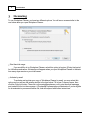
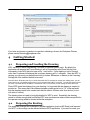

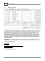


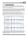
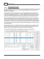
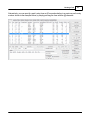

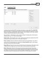

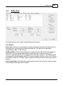
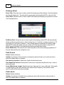

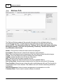
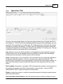

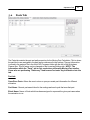

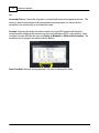
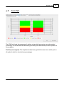
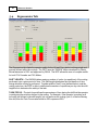
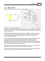
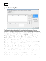

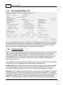
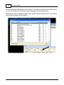
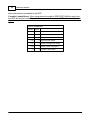
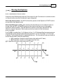
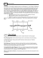


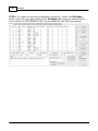
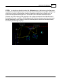
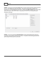
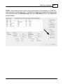
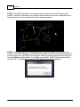
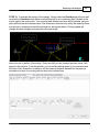
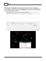
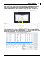
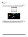
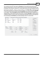
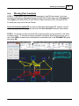
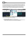
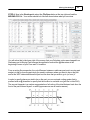
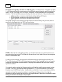
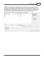


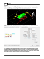

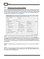
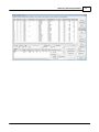
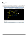
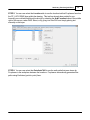
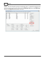
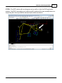
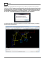
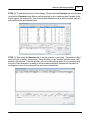
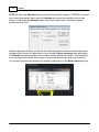
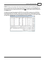
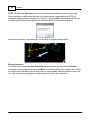
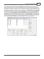
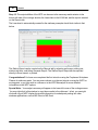
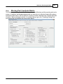
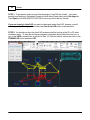
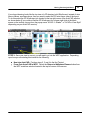
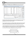
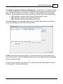
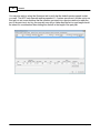
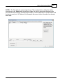
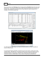

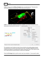

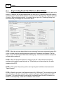
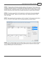
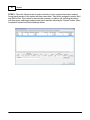
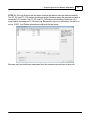
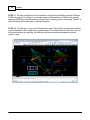
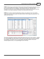
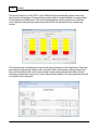


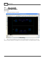
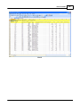
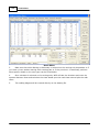
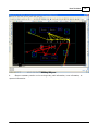
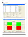
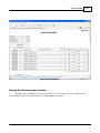
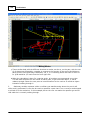
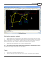
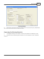
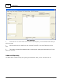
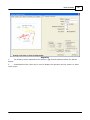
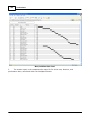
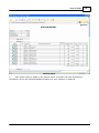
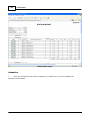
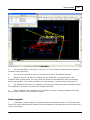


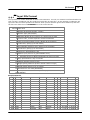


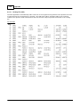
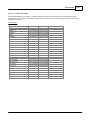
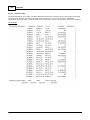
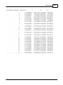


![[Scan] button on the ScanSnap.](http://vs1.manualzilla.com/store/data/005658366_1-513fc66afaf683e0c3b25d8948918383-150x150.png)