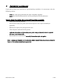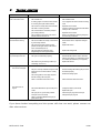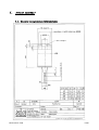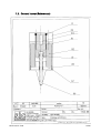
1
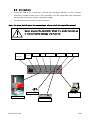
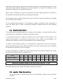
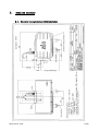
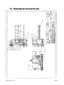
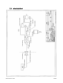
i141
USER MANUAL
SIC MARKING
13 route de Limonest
Z.A.C. de la Braille
69380 LISSIEU - FRANCE
Phone : (+33).04.72.54.80.00
Fax : (+33).04.78.47.39.40
E-Mail : [email protected]
http://www.sic-marking.com
NOTI141US – R00
TABLE OF CONTENTS
TABLE OF CONTENTS
3
PRESENTATION
5
INSTALLATION AND START-UP
7
1. Unpacking ...............................................................................................................7
2. Installation ..............................................................................................................7
2.1. Fastening............................................................................................................ 7
2.2. Connections ....................................................................................................... 8
USE OF THE MACHINE
9
1. Safety......................................................................................................................9
2. Controller................................................................................................................9
3. Software..................................................................................................................9
4. Marking machine.....................................................................................................9
4.1. Positioning and clamping of the part to be marked ............................................. 9
4.2. Machine adjustment ......................................................................................... 10
4.3. Launch / Stop the marking ............................................................................... 10
MAINTENANCE
13
1. Introduction ..........................................................................................................13
2. After-sales service.................................................................................................13
3. Preventive maintenance .........................................................................................14
4. Trouble shooting ...................................................................................................15
APPENDIX
17
1. stylus assembly .....................................................................................................19
1.1. General layout (overall dimensions) .................................................................. 19
1.2. General layout (References)............................................................................... 20
1.3. Terminology and references general layout....................................................... 21
1.4. Terminology and references spare parts ........................................................... 21
2. marking machine...................................................................................................23
2.1. General layout (overall dimensions) .................................................................. 23
2.2. I 141 Terminology and references..................................................................... 24
NOTI141US – R00
3/30
2.3. Terminology and references X-Y table .............................................................. 26
2.4. electrical chart .................................................................................................. 28
2.5. External connection cables (5 or 10 meters)...................................................... 29
2.6. Internal cabling plan ......................................................................................... 30
NOTI141US – R00
4/30
PRESENTATION
Thank you for choosing a dot marking system (also called micro-percussion) for your
marking applications.
SIC MARKING systems contribute to improve the tracability of your products while
complying with the industrial standards.
We would like to welcome you as a user of our systems.
This guide contains the installation and use instructions of the dot marking type
machines. We recommend that you read it carefully before installing the system.
Please contact our technical department for any further information.
NOTI141US – R00
5/30
NOTI141US – R00
6/30
INSTALLATION AND START-UP
1.
UNPACKING
Except if we deliver the system, it is generally supplied in an appropriate packaging,
which needs to be kept for any return of the material.
Remove the sub-systems carefully (controller, control handbox, possible options …) from
their packages.
The machine should only be lifted by the column and the
base ; it should never be lifted by the head housing.
Weight of the machine : 35 kg
2.
INSTALLATION
2.1. Fastening
Column-type machines
o
Install the machine on a rigid and stable support frame
o
After installing the entire marking machine, fasten the base with 2 M10
screws.
Integrated-type machines
o
Install the machine on a rigid and stable support frame
o
Fasten the marking head onto the machine by complying with the
indications of the integration plan, available thread length 12 mm max.
Portable-type machines
o
No fastening : marking gun designed to be held manually
Note : The integrated and portable type machines are designed to function in all
positions (vertical, horizontal, stylus towards the bottom or the top)
NOTI141US – R00
7/30
2.2. Connections
•
Using the SUB-D 25 connector, connect the marking machine to the "marker"
connector located at the rear of the controller. For the integrated type machines,
proceed the same way using a connection cable.
•
Correctly fasten the screws of the connector.
Note : for more details about the connections, please check the controller manual.
Never unplug the controller when it is under tension as
it may seriously damage the material.
switch on / off
Accessory
(3rd axis)
MARKER
I/O
START / STOP
KEYBOARD
SERIAL
HOST
power supply
PC
(port COM1)
control handbox
mechanical part
keyboard (option)
NOTI141US – R00
8/30
USE OF THE MACHINE
1.
SAFETY
An intense use may cause the temperature of the
system to rise up to 100°C.
It is recommended to wear safety glasses.
It is also recommended to wear a noise reducing
helmet.
Acoustic value of the machine : 76 dB on a piece of
steel at medium speed
The marking system should never be used without any
surface to mark as the marking head may break.
2.
CONTROLLER
See controller manual
3.
SOFTWARE
See software manual
4.
MARKING MACHINE
4.1. Positioning and clamping of the part to be marked
Even if the part is not submitted to high forces, it is necessary to immobilize it in order to
reach an optimal marking quality.
NOTI141US – R00
9/30
Depending on the type of parts and the working conditions, the clamping system can vary
from the simple manual fastening of the part against an angle iron (bracket) to the
mechanical, magnetic or pneumatic fastening.
When using a marking gun, place the universal non-skid support against the surface to
be marked and manually hold the gun during the marking.
The fastening device should maintain the part so that the stylus movements are parallel
to the surface to be marked.
For the portable type machines, if the marking is always conducted on the same type of
parts, we advise you to make a customized tooling to always keep the same marking
position.
4.2. Machine adjustment
The marking quality highly depends on the part to be marked ; a smooth and flat surface
is much easier to mark than a rough and irregular surface.
It is generally necessary to adapt the marking force to the height of the character. The
smaller the character is, the lower the impact has to be to obtain a good legibility. The
software also enables to choose various widths for the marking matrix.
To obtain a good marking quality, it is fundamental to adjust the force and the distance.
When using marking guns, the distance between the stylus and the part can be modified
by adjusting the position of the front plate.
For your information, hereafter are some values about the distance between the stylus
and the part depending on the marking force :
Force
1
2
3
4
5
6
7
8
9
Minimum distance
0.5
0.5
0.5
1
1
2
3
5
6
Maximum distance
1
2
3
5
6
7
9
9
9
Maximum distance between the stylus and the part : 9 mm
We recommend that you make trials before marking a new part.
4.3. Launch / Stop the marking
o
Set the controller in marking mode (for more information, please see the software
manual)
NOTI141US – R00
10/30
o
Position the part to be marked
o
Launch the marking by pressing the "Start" button on the control handbox or the
"Marche" button on the gun handle (portable type machine)
o
To stop the marking, press the "Stop" button on the control handbox or press the
"Marche" button of the gun handle for more than 2 seconds.
NOTI141US – R00
11/30
NOTI141US – R00
12/30
MAINTENANCE
1.
INTRODUCTION
Dot marking machines have been developed and realized especially to meet the needs
of our clients who want a machine which is :
-
Performing,
-
Robust,
-
Reliable,
-
Ergonomic.
It requires very little maintenance and if you observe the preventive maintenance
recommendations, you will increase the life-expectancy of your machine.
However, if a problem of any kind should occur, please refer to this manual, which will
help you solve the problem.
2.
AFTER-SALES SERVICE
Please contact our local distributor first.
To find out about our local distributor, you can check our website :
www.sic-marking.com
If you can not reach our distributor, please call SIC MARKING at +33.4.72.54.80.00.
SIC MARKING or its distributor offer the following services :
Phone support
Please do not hesitate to contact us for any technical problem.
On-site intervention
We can help you install, set up the machine on-site, as well as repair it and provide
personal training.
Maintenance contract
Thanks to the maintenance contract, we provide regular maintenance of your marking
machine.
NOTI141US – R00
13/30
3.
PREVENTIVE MAINTENANCE
If you want to keep your machine in a good working condition, it is necessary to do the
following actions :
-
clean the stylus pin guide and the stylus assembly regularly
-
avoid dust and abrasive particles on the guiding and driving elements
How to clean the stylus pin guide and the stylus assembly
-
Unplug the marking machine
-
Unscrew the stylus pin guide (see General layout of the stylus assembly in
appendix)
-
Remove the stylus, the spring and the core
-
Clean all parts and remove the grease
-
Lubricate the stylus and the stylus pin guide using exclusively the oil supplied
with your maintenance kit.
-
Reassemble the machine and manually fasten the stylus pin guide
Note : please pay attention to the direction when reassembling the core (see General
layout of the stylus assembly in appendix)
NOTI141US – R00
14/30
4.
TROUBLE SHOOTING
Problem
The stylus assembly does not
move on the X and Y axes
Check
Check that :
-
The controller is on
-
See controller manual
-
A marking program is loaded and the controller
is in marking mode (see software manual)
-
Load a program and set the machine in marking
mode
-
The machine is correctly linked to the controller
-
Reposition the connectors
-
The cable is in working condition
-
-
The control handbox is connected (except for
gun marking machines)
Open the connectors and check the wires either
visually or with a ohmmeter.
-
Reposition the connectors
-
Remove any obstacle or clean the guiding rails
and the driving mechanisms
The marking head does not go
back home before marking
The stylus assembly moves
(X,Y) but the stylus does not
The marking quality is terrible :
-
The movements on the X and Y axes are not
blocked when the machine is on.
Check that :
-
The sensors cables are correctly connected and
in good working condition
-
Reconnect the wires or replace the damaged
cables
-
The origin sensors work properly (in home
position, the red lights located on the sensors
are off, otherwise they are on).
-
Replace the sensors
-
The driving belts are not broken on the
integrated type or column type machines
-
Replace the damaged belt
Check that :
-
The stylus is not blocked by anything
-
Disassemble the machine, clean it, lubricate it
with the oil provided in your maintenance kit and
re-assemble (see General layout in appendix)
-
The solenoid is in good working condition (no
overheating, short circuit…)
-
Replace the solenoid
Check that :
The dots are not aligned
-
-
-
Solution
The impacts are not
regular
The part is correctly maintained during the entire marking process and the machine is correctly
fastened
The marking speed is not too high compared
with the marking to be made (size)
Redo the marking after fastening the part and/or
the machine properly
Reduce the marking speed
-
There is no backlash in the X and Y axes
-
Please contact the after sales service
-
The distance between the stylus and the part is
correct
-
Change the distance (see manual)
-
Replace the stylus
-
The stylus pin is in good working condition
-
Clean the stylus pin guide and the stylus
-
The stylus can move correctly
-
Change the stylus pin guide
-
There is no backlash between the stylus pin
guide and the stylus
If you have checked everything and the system still does not work, please contact our
after sales services.
NOTI141US – R00
15/30
APPENDIX
NOTI141US – R00
17/30
NOTI141US – R00
18/30
1.
STYLUS ASSEMBLY
1.1. General layout (overall dimensions)
NOTI141US – R00
19/30
1.2. General layout (References)
NOTI141US – R00
20/30
1.3. Terminology and references general layout
REF
QTY
CODE
DESCRIPTION
1
1
Body
2
1
Solenoid
3
1
Core
4
1
Support mount
5
1
Stylus guide l 60
6
1
Stylus pin l 60
10
1
Spring
11
1
O ring
12
1
Locking O ring
1.4. Terminology and references spare parts
REF
QTY
CODE
DESCRIPTION
1à4
1
3 200 003
Solenoid assembly
6
1
1 120 012
Stylus pin L 60
5
1
1 120 017
Stylus guide L 60
1
1 120 013
Stylus pin L 80
1
1 120 023
Stylus guide L 80
1
1 120 014
Stylus pin L 100
1
1 120 024
Stylus guide L 100
1
2 120 006
Spring
10
NOTI141US – R00
21/30
NOTI141US – R00
22/30
2.
MARKING MACHINE
2.1. General layout (overall dimensions)
NOTI141US – R00
23/30
2.2. I 141 Terminology and references
NOTI141US – R00
24/30
REF
NOTI141US – R00
QTY
CODE
DESCRIPTION
1
4 100 312
X-Y mechanism
1
1 220 073
Cover with identification
1
3 100 040
Power cable
2
1 310 010
Side cap
1
3 100 037
Intermediate cable
2
3 100 038
X and Y motor cable
1
1 220 017
Sheet metal 2 way connector support
1
1 310 014
Carriage and support frame
1
1 110 093
Bracket
1
1 110 094
table fixation plate
1
1 120 096
fixation plate
1
1 110 095
bellow support
1
1 220 074
bellow 1
1
1 220 075
bellow 2
1
1 220 076
bellow 3
1
1 220 077
bellow 4
1
1 220 078
bellow 5
1
1 220 080
bellow 6
2
1 220 079
bellow support bracket
2
2 120 090
pin ∅5 x 20
25/30
2.3. Terminology and references X-Y table
NOTI141US – R00
26/30
REF
QTY
CODE
DESCRIPTION
16
1
1 110 066
X axis mount
11
1
1 110 067
Y axis mount
12
1
1 110 068
Y chariot
19
1
1 220 057
X motor mount
14
1
1 220 058
Y motor mount
21
1
1 220 058
X lead screw support
23
1
1 220 059
Y lead screw support
6
2
1 120 073
Bushing
13
1
4 100 318
X axis lead screw + nut mount
8
1
4 100 319
Y axis lead screw + nut mount
22
1
2 120 018
X guiding rail
24
1
2 120 016
Y guiding rail
15
1
2 230 055
Wired X motor
18
1
2 230 054
Wired Y motor
7
2
2 120 021
608ZZ ball bearing
5
2
2 120 080
Bearing
17
2
2 110 003
Pressure screw
1
2
1 120 019
Washer
10
2
2 120 010
Motor pulley
2
2
2 120 011
Axis pulley
9
1
2 120 023
X driving belt
3
1
2 120 035
Y driving belt
20
2
2 230 004
Origin sensor
4
2
2 120 022
Seal
25
1
2 110 005
detection screw
26
1
2 110 006
pin ∅4x32
NOTI141US – R00
27/30
2.4. electrical chart
NOTI141US – R00
28/30
2.5. External connection cables (5 or 10 meters)
SUB D 25
19 pins
color
color
connector
connector
(standard cable)
(ROBOTIC cable)
1
12
purple
green & brown
solenoid 1
2
12
black
green & white
solenoid 1
4
3
brown & gray
red & brown
Y axis motor
5
4
whie & gray
red & white
Y axis motor
6
5
brown
blue & brown
Y axis motor
7
7
white
blue & white
Y axis motor
8
8
yellow
pink
X axis motor
9
9
green
gray
X axis motor
10
10
brown & green
pink & white
X axis motor
11
11
green & white
pink & gray
X axis motor
12
1
pink
white
start / stop button
13
2
gray
brown
start / stop button
14
12
red
yellow
solenoid 1
15
12
blue
green
solenoid 1
16
18
white & yellow
red & blue
Dallas bus
17
13
red & blue
red
"L" & "+" sensors
18
14
pink & gray
blue
"-" sensors
19
17
yellow & brown
gray & pink
Dallas ground
20
15
red & white
black
Y sensor
21
16
red & brown
purple
X sensor
22
6
blue & white
yellow & brown
solenoid 2
23
6
brown & blue
yellow & white
solenoid 2
24
6
pink & brown
white & gray
solenoid 2
25
6
pink & white
gray & brown
solenoid 2
NOTI141US – R00
element
29/30
2.6. Internal cabling plan
19 pins
8 pins
12 pins
connector
connector
connector
color
element
3
1
gray & pink
Y axis motor (red)
4
2
green
Y axis motor (yellow)
5
3
gray
Y axis motor (blue)
6
9
blue
solenoid 2
7
4
red & blue
Y axis motor (orange)
8
1
black
X axis motor (red)
9
2
white & gray
X axis motor (yellow)
10
3
white & green
X axis motor (orange)
11
4
white & yellow
X axis motor (blue)
green & yellow
solenoid 1
yellow & brown
"L" & "+" sensors
yellow & brown
"L" & "+" sensors
brown & green
"-" sensors
12
13
8
5
13
14
5
6
14
6
brown & green
"-" sensors
15
7
yellow
Y sensor
white
X sensor
16
7
17
11
brown & gray
Dallas ground
18
12
white & red
Dallas bus
NOTI141US – R00
30/30