1
c151-ZA / c151-ZAI
USER MANUAL
SIC MARKING
13 route de Limonest
Z.A.C. de la Braille
69380 LISSIEU - FRANCE
Phone : (+33).04.72.54.80.00
Fax : (+33).04.78.47.39.40
E-Mail : { HYPERLINK
"mailto:[email protected]" }
{ HYPERLINK "http://www.sicmarking.com" }
{ FILENAME \* MERGEFORMAT }
TABLE OF CONTENTS
{ TOC \O "1-3" \H \Z
{ FILENAME \* MERGEFORMAT }
}
{ PAGE }/31
PRESENTATION
Thank you for choosing a dot marking system (also called micro-percussion) for your
marking applications.
SIC MARKING systems contribute to improve the tracability of your products while
complying with the industrial standards.
We would like to welcome you as a user of our systems.
This guide contains the installation and use instructions of the dot marking type
machines. We recommend that you read it carefully before installing the system.
Please contact our technical department for any further information.
{ FILENAME \* MERGEFORMAT }
{ PAGE }/31
{ FILENAME \* MERGEFORMAT }
{ PAGE }/31
INSTALLATION AND START-UP
1.
UNPACKING
Except if we deliver the system, it is generally supplied in an appropriate packaging,
which needs to be kept for any return of the material.
Remove the sub-systems carefully (controller, control handbox, possible options …) from
their packages.
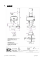
The machine should only be lifted by the column and the
base ; it should never be lifted by the head housing.
Weight of the machine : 41 kg
2.
INSTALLATION
2.1. Fastening
Column-type machines
o
Install the machine on a rigid and stable support frame
o
After installing the entire marking machine, fasten the base with 2 M10
screws.
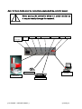
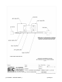
2.2. Connections
plug :
•
The marking head to the "MARKER" plug of the controller (through the ROBOTIC
5m cable)
•
The digital column to the "ACCESSORY" plug of the controller (cable e6/accessory)
•
The start button box to the "START / STOP" plug of the controller
•
The autosensing cable to the "I/O" plug of the controller
{ FILENAME \* MERGEFORMAT }
{ PAGE }/31
Note : for more details about the connections, please check the controller manual.
Never unplug the controller when it is under tension as
it may seriously damage the material.
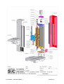
switch on / off
Accessory
(3rd axis)
MARKER
I/O
START / STOP
KEYBOARD
SERIAL
HOST
power supply
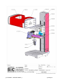
PC
(port COM1)
control handbox
mechanical part
keyboard (option)
{ FILENAME \* MERGEFORMAT }
{ PAGE }/31
USE OF THE MACHINE
1.
SAFETY
An intense use may cause the temperature of the system
to rise up to 100°C.
It is recommended to wear safety glasses
It is also recommended to wear a noise reducing helmet.
Acoustic value of the machine : 76 dB on a piece of steel
at medium speed
The marking system should never be used without any
surface to mark as the marking head may break.
The machine must be surrounded by a housing or by
a light curtain.
The Autosensing option is not a security function of the
digital Z axis
2.
CONTROLLER
See software manual
3.
SOFTWARE
See software manual
{ FILENAME \* MERGEFORMAT }
{ PAGE }/31
4.
MARKING MACHINE
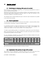
4.1. Positioning and clamping of the part to be marked
Even if the part is not submitted to high forces, it is necessary to immobilize it in order to
reach an optimal marking quality.
Depending on the type of parts and the working conditions, the clamping system can vary
from the simple manual fastening of the part against an angle iron (bracket) to the
mechanical, magnetic or pneumatic fastening.
The fastening device should maintain the part so that the stylus movements are parallel
to the surface to be marked.
4.2. Machine adjustment
The marking quality highly depends on the part to be marked ; a smooth and flat surface
is much easier to mark than a rough and irregular surface.
It is generally necessary to adapt the marking force to the height of the character. The
smaller the character is, the lower the impact has to be to obtain a good legibility. The
software also enables to choose various widths for the marking matrix.
To obtain a good marking quality, it is fundamental to adjust the force and the distance.
When using marking guns, the distance between the stylus and the part can be modified
by adjusting the position of the front plate.
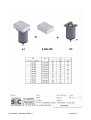
For your information, hereafter are some values about the distance between the stylus
and the part depending on the marking force :
Force
1
2
3
4
5
6
7
8
9
Minimum distance
0.5
0.5
0.5
1
1
2
3
5
6
Maximum distance
1
2
3
5
6
7
9
9
9
Maximum distance between the stylus and the part : 9 mm
We recommend that you make trials before marking a new part.
4.3. Adjustment of the position of origin of the column
The column’s manual adjustment is performed thanks to the rule on the side of the
column. The 2 screws on the back side of the column enable to move the rule.
{ FILENAME \* MERGEFORMAT }
{ PAGE }/31
Important remarks :
•
•
The motorized column with the marking head (stylus 60mm long), is made with a
250mm stroke.
•
•
At the high position (the highest origin location possible) the distance stylus-base
is 250mm
•
•
At the low position (the lowest origin location possible) the distance stylus-base is
20mm
The steps are the followings :
•
•
From the main menu (marking mode), please go into EDIT (F5)
•
•
Create the file with the AUTO Z (ALT+A)
•
•
Come back into the marking mode
•
•
Start the marking : the machine’s head will go down / find a point / and go up
after
•
•
During the up movement push on the button « STOP »
•
•
Unplug the power supply cable from the e6
•
•
Unscrew the 2 little screw inside the groove of the rule (on the side of the column)
•
•
Move the rule to reach the origin position wished
•
•
Screw again the 2 screws of the rule
•
•
Plug the power supply for the e6
{ FILENAME \* MERGEFORMAT }
{ PAGE }/31
4.4. Launch / Stop the marking
o
Set the controller in marking mode (for more information, please see the software
manual)
o
Position the part to be marked
o
Launch the marking by pressing the "Start" button on the control handbox
o
To stop the marking, press the "Stop" button on the control handbox.
{ FILENAME \* MERGEFORMAT }
{ PAGE }/31
{ FILENAME \* MERGEFORMAT }
{ PAGE }/31
MAINTENANCE
1.
INTRODUCTION
Dot marking machines have been developed and realized especially to meet the needs
of our clients who want a machine which is :
-
Performing,
-
Robust,
-
Reliable,
-
Ergonomic.
It requires very little maintenance and if you observe the preventive maintenance
recommendations, you will increase the life-expectancy of your machine.
However, if a problem of any kind should occur, please refer to this manual, which will
help you solve the problem.
2.
AFTER-SALES SERVICE
Please contact our local distributor first.
To find out about our local distributor, you can check our website :
{ HYPERLINK "http://www.sic-marking.com" }
If you can not reach our distributor, please call SIC MARKING at +33.4.72.54.80.00.
SIC MARKING or its distributor offer the following services :
Phone support
Please do not hesitate to contact us for any technical problem.
On-site intervention
We can help you install, set up the machine on-site, as well as repair it and provide
personal training.
Maintenance contract
Thanks to the maintenance contract, we provide regular maintenance of your marking
machine.
{ FILENAME \* MERGEFORMAT }
{ PAGE }/31
3.
PREVENTIVE MAINTENANCE
If you want to keep your machine in a good working condition, it is necessary to do the
following actions :
-
clean the stylus pin guide and the stylus assembly regularly
-
avoid dust and abrasive particles on the guiding and driving elements
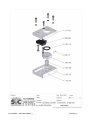
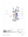
How to clean the stylus pin guide and the stylus assembly
-
Unplug the marking machine
-
Unscrew the stylus pin guide (see General layout of the stylus assembly in
appendix)
-
Remove the stylus, the spring and the core
-
Clean all parts and remove the grease
-
Lubricate the stylus and the stylus pin guide using exclusively the oil supplied
with your maintenance kit.
-
Reassemble the machine and manually fasten the stylus pin guide
Note : please pay attention to the direction when reassembling the core (see General
layout of the stylus assembly in appendix)
{ FILENAME \* MERGEFORMAT }
{ PAGE }/31
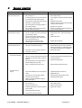
4.
TROUBLE SHOOTING
Problem
The stylus assembly does not
move on the X and Y axes
Check
Check that :
-
The controller is on
-
See controller manual
-
A marking program is loaded and the controller
is in marking mode (see software manual)
-
Load a program and set the machine in marking
mode
-
The machine is correctly linked to the controller
-
Reposition the connectors
-
The cable is in working condition
-
-
The control handbox is connected (except for
gun marking machines)
Open the connectors and check the wires either
visually or with a ohmmeter.
-
Reposition the connectors
-
Remove any obstacle or clean the guiding rails
and the driving mechanisms
The marking head does not go
back home before marking
The stylus assembly moves
(X,Y) but the stylus does not
The marking quality is terrible :
-
The movements on the X and Y axes are not
blocked when the machine is on.
Check that :
-
The sensors cables are correctly connected and
in good working condition
-
Reconnect the wires or replace the damaged
cables
-
The origin sensors work properly (in home
position, the red lights located on the sensors
are off, otherwise they are on).
-
Replace the sensors
-
The driving belts are not broken on the
integrated type or column type machines
-
Replace the damaged belt
Check that :
-
The stylus is not blocked by anything
-
Disassemble the machine, clean it, lubricate it
with the oil provided in your maintenance kit and
re-assemble (see General layout in appendix)
-
The solenoid is in good working condition (no
overheating, short circuit…)
-
Replace the solenoid
Check that :
The dots are not aligned
-
-
-
Solution
The impacts are not
regular
The digital column don’t move
The part is correctly maintained during the entire marking process and the machine is correctly
fastened
The marking speed is not too high compared
with the marking to be made (size)
Redo the marking after fastening the part and/or
the machine properly
Reduce the marking speed
-
There is no backlash in the X and Y axes
-
Please contact the after sales service
-
The distance between the stylus and the part is
correct
-
Change the distance (see manual)
-
Replace the stylus
-
The stylus pin is in good working condition
-
Clean the stylus pin guide and the stylus
-
The stylus can move correctly
-
Change the stylus pin guide
-
There is no backlash between the stylus pin
guide and the stylus
Check that :
-
The controller is on
-
See controller manual
-
The type of machine is bad
-
See the machine manual
-
Chek that digital column is correctly connected
to the controller
-
Replace the connector
-
Check that the state of the cable
-
Check that any mechanical blocking
{ FILENAME \* MERGEFORMAT }
{ PAGE }/31
If you have checked everything and the system still does not work, please contact our
after sales services.
{ FILENAME \* MERGEFORMAT }
{ PAGE }/31
ANNEXES
{ FILENAME \* MERGEFORMAT }
{ PAGE }/31
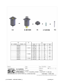
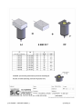
1.
C151-ZA
{ FILENAME \* MERGEFORMAT }
{ PAGE }/31
{ FILENAME \* MERGEFORMAT }
{ PAGE }/31
{ FILENAME \* MERGEFORMAT }
{ PAGE }/31
{ FILENAME \* MERGEFORMAT }
{ PAGE }/31
{ FILENAME \* MERGEFORMAT }
{ PAGE }/31
{ FILENAME \* MERGEFORMAT }
{ PAGE }/31
{ FILENAME \* MERGEFORMAT }
{ PAGE }/31
{ FILENAME \* MERGEFORMAT }
{ PAGE }/31
{ FILENAME \* MERGEFORMAT }
{ PAGE }/31
{ FILENAME \* MERGEFORMAT }
{ PAGE }/31
{ FILENAME \* MERGEFORMAT }
{ PAGE }/31
{ FILENAME \* MERGEFORMAT }
{ PAGE }/31
{ FILENAME \* MERGEFORMAT }
{ PAGE }/31
{ FILENAME \* MERGEFORMAT }
{ PAGE }/31
{ FILENAME \* MERGEFORMAT }
{ PAGE }/31
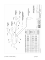
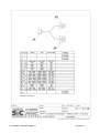
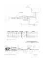
câble de liaison (5 ou 10 mètres)
robotic cable (5 or 10 meters)
connecteur
connecteur
SUB D 25 male
19 voies
1
couleur
color
Code couleur
12
vert & marron
green – brown
GN – BN
2
12
vert & blanc
green - white
GN – WH
4
3
rouge & marron
red – brown
RD – BN
5
4
rouge & blanc
red – white
RD – WH
6
5
bleu & marron
blue – brown
BU – BN
7
7
bleu & blanc
blue – white
BU – WH
8
8
rose
pink
PK
9
9
gris
grey
GY
10
10
rose & blanc
pink – white
PK – WH
11
11
rose & gris
prink – grey
PK – GY
12
1
blanc
white
WH
13
2
marron
brown
BN
14
12
jaune
yellow
YE
15
12
vert
green
GN
16
18
rouge & bleu
red – blue
RD – BU
17
13
rouge
red
RD
18
14
bleu
blue
BU
19
17
gris & rose
grey – pink
GY – PK
20
15
noir
black
BK
21
16
violet
purple
VT
22
6
jaune & marron
yellow – brown
YE – BN
23
6
jaune & blanc
yellow – white
YE – WH
24
6
blanc & gris
white – grey
WH – GY
25
6
gris & marron
grey - brown
GY – BN
Code couleur suivant IEC757
{ FILENAME \* MERGEFORMAT }
{ PAGE }/31
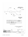
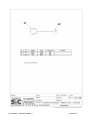
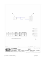
câble socle colonne numérique (5 ou 10 mètres)
digital axis cable (5 or 10 meters)
connecteur
connecteur
SUB D 15 male
9 voies
1
couleur
color
Code couleur
1
blanc
white
WH
2
2
marron
brown
BN
3
3
vert
green
GN
4
4
jaune
yellow
YE
6
6
gris
grey
GY
7
7
rose
pink
PK
8
5
bleu
blue
BU
couleur
color
Code couleur
Code couleur suivant IEC757
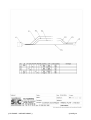
câble autosensing (5 ou 10 mètres)
autosensing cable (5 or 10 meters)
connecteur
connecteur
SUB D 37 male
5 voies
18
1
blanc
white
WH
19
2
marron
brown
BN
9
3
vert
green
GN
8
4
jaune
yellow
YE
Code couleur suivant IEC757
{ FILENAME \* MERGEFORMAT }
{ PAGE }/31
2.
C151-ZAI (SPECIFICITIES)
{ FILENAME \* MERGEFORMAT }
{ PAGE }/31
{ FILENAME \* MERGEFORMAT }
{ PAGE }/31
{ FILENAME \* MERGEFORMAT }
{ PAGE }/31
{ FILENAME \* MERGEFORMAT }
{ PAGE }/31
{ FILENAME \* MERGEFORMAT }
{ PAGE }/31
{ FILENAME \* MERGEFORMAT }
{ PAGE }/31
{ FILENAME \* MERGEFORMAT }
{ PAGE }/31
Nom du document : NOTC151ZAUS - R02.doc
Dossier :
V:\04 - Produits\007 - C151-ZA\01 - Notices\US
(ANGLAIS)
Modèle :
C:\Documents and Settings\sic39\Application
Data\Microsoft\Modèles\Normal.dot
Titre :
introduction
Sujet :
Auteur :
SIC21
Mots clés :
Commentaires :
Date de création :
27/06/2006 14:37
N° de révision :
3
Dernier enregistr. le :
27/06/2006 14:39
Dernier enregistrement par :
Temps total d'édition :
sic39
3 Minutes
Dernière impression sur : 28/06/2006 09:23
Tel qu'à la dernière impression
Nombre de pages :
42
Nombre de mots :
1 951 (approx.)
Nombre de caractères :
11 122 (approx.)