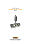
1
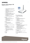
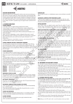
VTM
User’s Manual
As of version: V.09.10.00
Küppers Elektromechanik GmbH
Quality system certified to DIN EN ISO 9001
2
VTM User’s Manual
Contents
1. General, p. 4
5. Programming, p. 14
1.1 Application, p. 4
5.1 Start the programming mode, p. 15
1.2 Ordering Inforamtion, p. 4
5.2 Entering numerical parameters, p. 15
5.3 Selecting from presets, p. 15
2. Specifications, p. 5
2.1 Technical data, p. 5
2.2 Dimensional drawings, p. 6
2.3 Functional diagram, p. 7
2.4 Outputs, p. 7
2.4.1 Pulse output, p. 7
2.4.2 Analogue output, p. 8
2.5 Notes on installation, p. 8
3. Start up, p. 9
3.1 Error and status messages, p. 9
3.2 MPU programme flow chart, p. 10
4. Measuring mode, p. 11
5.4 Level »Paramet« – operational parameters, p. 16
5.4.1 Table of parameters, p. 16
5.4.2 Invalid programming, p. 16
5.5 Parameters, p. 16
5.5.1 K-factor of the flow meter, p. 16
5.5.2 Flow Dim, flow rate unit, p. 17
5.5.3 Flow-DP; decimal point, p.17
5.5.4 F-Cut, cut off frequency, p. 17
5.5.5 Density, p. 17
5.5.6 Gate, p. 18
5.5.7 Gate mem
5.5.8 Pulse-time, p. 18
5.5.9 Divider, p. 19
5.5.10 Analog, full scale, p. 19
5.5.11 A-Time, Response time of the analogue output, p. 19
5.5.12 Linear, activate linearisation, p. 19
5.5.13 Key-Res, reset via keyboard, p. 19
5.5.14 Dis-Mode, display mode in the measuring mode, p. 19
5.5.15 Imp-Out, signal source of the pulse output, p. 20
5.5.16 A-Test, check of the analogue output, p. 20
5.5.17 Clearmem, restoring defaults, p. 20
5.6 Level »Linear«, Linearisation, p. 21
4.1 Measuring masks, p. 11
4.1.1 Real-time value, p. 11
4.1.2 Totals, p. 11
4.1.3 Direct measuring frequency, p. 12
4.1.4 Gate frequency, p. 12
4.1.5 Direct pickup pulses, p. 12
4.1.6 Digital/Analogue value, p. 12
4.1.7 Analogue out factor, p. 12
4.1.8 Divider in direct pickup pulses, p. 12
4.1.9 K-Faktor in programmed unit, p. 13
4.1.10 Programming counter, p. 13
KEM
6. Installation, p. 22
6.1 Installation on flow meter, p. 22
6.2 Positioning the VTM housing, p. 22
6.3 Positioning the display, p. 22
3
1. General
1.1 Application
The VTM is a programmable local display with integral carrier-frequency pickup
and amplifier for KEM flow meters. It serves the evaluation of flow volumes.
Measuring results are indicated in an 8 digit LCD display with 14 segments. The
Display
pulse output provides a flow-proportional frequency signal or scaled volume
E
pulse in accordance with programming. Optionally the measuring signal may be
1.2345
scaled in a 4-20 mA current loop.
Reset
The display is available in two different arrangements to fit various installing
P
positions (see drawing p. 6). The electronic housing is slewable by 360°, in addition the display unit may be positioned in steps of 90° (see p. 22). These features
guarantee for an excellent readability independent of the installing position.
For electrical connection a 6-pin plug or a junction box with 6 internal terminals is provided.
1.2 Ordering Information
VTM * * * * * Ex
Ex-protection
electrical connection
cover
pickup
display arrangement
signal output
4
Ex = Ex-protection ATEX 100a EX II 2 G EEx ia IIC T4
K = junction box
S = protective cover with glass window
K = for ZHM 02 to 04 and HM series
R = for ZHM 01, 01/1 and 01/2 as well as SRZ series
S = centre pickup for ZHM series
D = top view
B = frequency output/divider and analogue output
VTM User’s Manual
2. Specifications
2.1 Technical Data
General
LCD display:
8 digits (14 segments), digit height 7 mm
for real-time value, totals and programming,
slewable in steps of 90° after losening the fixing screws
–40 up to +70 °C
–40 up to +120 °C with a distance of at least 25 mm
between flow meter and electronic housing
junction box with 6 internal terminals
ambient temperature:
medium temperature:
electrical connection:
plug KVM / KVC
3
4
2
5
1
6
1
+UB (Imp)
2
Out (Imp)
3
Com (Imp)
4
- IA
5
+ IA
6
shield
Ex-protection ATEX 100a: EX II 2 G EEx ia IIC T4, BVS 03 ATEX E 205
safety-relevant data as per Ex-certificate
protection class:
IP 65
housing:
aluminium AlMgSiPb, blue anodised, slewable by 360°
Frequency output/divider
operating mode:
supply voltage:
quiescent current (IR):
signal output:
3-wire
8–30 V DC controlled
< 25 mA
push/pull
Imax: 20 mA
1. frequency output:
fmax: 3,000 Hz
duty cycle: approx. 1:1
2. divider:
pulse width: 1 ms, 20 ms, 50 ms
fmax: 500 Hz
Analogue output
operating mode:
supply voltage:
load:
resolution:
time constant:
signal output:
KEM
2-wire (4–20mA)
14–30 V DC controlled
UB = (Rload x 20 mA) + 14 V
< 800 Ω
12 bit (3,9 µA)
slow or fast (programmable under “A-TIME”)
4–20 mA
5
Specifications
2.2 Dimensional drawings (mm)
display arrangement »front view«
97
97
Display
Reset
P
E
1.2345
148
1.2345
Reset
P
178
E
∅85
Display
junction
box
∅ 85
M5
50
97
display arrangement »top view«
50
junction
box
1.2345
Reset
P
E
∅85
1.2345
Reset
95
Display
E
∅ 85
Display
125
M5
97
P
103
»front view« with protective cover
»top view« with protective cover
∅ 93
M5
Display
79
E
P
148
1.2345
Reset
135
6
VTM User’s Manual
Specifications
2.3 Functional diagram
pickup
key
display
micro processor
_
+
D/A
4
supply
_
I
+I
5
DC
DC
1
UB
2
3
6
0V
shield
2.4 Outputs
2.4.1 Pulse output
The VTM may optionally be equipped with a pulse output which can either provide standardised
pulses (e.g. in m³) or the direct measuring frequency of the flow meter (programmable via parameter IMP-OUT).
The wiring is as follows:
pulse counter
VTM pulse output
+8 to 30VDC
+UB
1
470
Out
only for supply of the galvanically
separated pulse input stage
pulse input
2
0V
COM
shield
KEM
3
6
7
Specifications
2.4.2 Analogue output 4–20 mA
The primary current of 4 mA powers the entire electronic of the VTM. The measuring signal of up to
16 mA is added resulting in a current consumption of 4 to 20 mA. The wiring may be taken from the scheme
below:
VTM: 4-20 mA
I+
power supply with evaluation 4-20 mA
5
UB (cf. technical data)
load
d/dt
+
0
out
I-
4
-
0V
shield
6
2.5 Notes on installation
Connect metal housing with PE
Built-in devices have to be installed in a metal housing connected with protected earth.
Observe a low impedance connection of PE and a measurement of the PE resistor according to VDE 0701. Also
observe a sufficient shielding for the employed cabinet.
Keep distance
Keep current-carrying cables at least 30cm away from the VTM. Only shall indicated terminals and contacts be
used for power supply. Keep mobiles, ISM-units or switching inductivities like engines or solenoid valves at
least 2 metres away from the digital measuring and control electronics. Avoid sources of electrostatic charges
in the closer environment of the VTM. Operators should also consider appropriate clothing and wear of shoes
with discharging ability.
Avoid parallel arrangement of current-carrying cables
8
VTM User’s Manual
Start up
3. Start up
After connecting the power supply the following messages will appear in the display:
read-dat
VTM
v-22.07.99
test reg
*okay*
All outputs take a neutral state. Parameters in the E
are being read.
Type
Software version
Calculation of all working parameters.
On successful check of all data the VTM will automatically activate the meas uring
mode and display the current operational parameters in accordance with the
selected measuring mask.
Please note
P-Error
Parameter are saved twice in different banks of the EEPROM. In case of deviations
between both parameter banks the display will show an error message.
Press E to restore all defaults and reset the totaliser to 0000. Afterwards the operation software will start the
programming mode and parameter settings may be repeated.
Please note:
The restoring of defaults may be started manually at any time (cf. programming of parameter CLEAR).
3.1 Error and status messages
During the measuring mode of after programming the following messages may appear in the display:
Message
CLEAR
P-ERROR
overflow
Description
erasing EEPROM/data memory
parameter error in EEPROM, proceed with E
display range exceeded, measuring value cannot be indicated
set.def
set defaults in MPU-RAM
w
cut off frequency passed
READ-DAT
copying data to MPU-RAM
test-reg
calculating operational parameters
write
KEM
writing data in EEPROM
9
Start up
3.2 MPU programme flow chart
The scheme shows the job stream of the MPU unit and the operation facilities during the measuring mode
considering the parameters KEY-RES and DIS-MODe.
connect power
copy data to MPU
message: Read-dat
type
message:
VTM
software version
message: v09.10.00
calculating parameters
message: test reg
message: * okay *
active measuring mode:
- process analogue output
- process pulse output
- display values
- process totaliser
display meas. or test screen
e. g. Q = 0000.00 m³/h
overflow
Reset
Display
P + E
10
yes
yes
yes
yes
measuring value cannot be
indicated
message: overflow
key-res = key-res
yes
reset of totaliser
yes
outputs neutral
programming
parameters
select next meas.
or test screen
3 sec?
VTM User’s Manual
Measuring mode
4. Measuring mode
The measuring mode allows for indicating either real-time values or totals. Press c to select the desired measuring mask. On the furthest left-hand digit your selection is indicated by a Q for real-time value or V for totals.
The way of indication (decimal point, flow rate unit etc.) depends on the adjustments in level paramet.
In case the special character W should appear right to the display description (Q or V), the cut off frequency,
parameter F-CUT, has been passed.
For start up or test purposes the display mode may be changed to test mode by programming the parameter
DIS-MODE to Test-Mod (cf. p. 19). In the test mode the display may indicate up to 10 different measuring masks as
listed in the table below.
4.1 Measuring masks
Meas. mask
Q
V
2
3
4
5
6
7
8
9
Display
real time value
totals
direct meas. frequency
gate frequency
direct transmitter pulses
D/A value
analogue out factor
divider
K-factor
programming counter
(not displayed)
Unit
Start up
Dis-mode = Test-mod
Meas. mode
DIS-MODE = MESS-MOD
flow rate unit
flow rate unit
000.0 Hz
000.0 Hz
pulses
decimal (0..4095)
none
pulses
flow rate unit
none
yes
yes
yes
yes
yes
yes
yes
yes
yes
yes
yes
yes
no
no
no
no
no
no
no
no
4.1.1 Real-time value (measuring mask Q)
The real-time value is indicated in accordance with the adjusted flow rate unit Flow-Dim and decimal point position Flow-DP. The calculation is based on the currently measured frequency and the K-factor of the flow meter.
The calculation is upgraded every 0.5 sec corresponding to approx. 2 Hz. The internal upgrading and resultant
response time of the analogue output and divider depends on the parameters Gate-Time and A-time.
4.1.2 Totals (measuring mask V)
The integral totaliser of the VTM adds the transmitter pulses standardised in the adjusted flow rate unit (FlowDim). Thus flow rates over a long period of time may be detected. The decimal point position depends on the
adjusted flow rate unit. The VTM will automatically display totals as accurate as possible.
Example: flow rate unit = m³/h. Totals are indicated in m³, e. g. 12.345 m³
If the measuring value exceeds the display range, it will be assigned accordingly (e. g. 1234.567m³will be display as 1234.56m³). If the measuring value is too high to be displayed by fading out digits, it will be displayed
using exponential notation (e. g. 1234567.89m³ will be displayed 1.23E06).
The totaliser may be reset via key provided that the parameter KEY-RES is programmed accordingly.
KEM
11
Measuring mode
The following masks are only available in the test mode of the display (cf. p. 18)
4.1.3 Direct measuring frequency (measuring mask 2)
With start up or service requirements it may be of advantage to indicate the transmitter frequency. Select
mask 2 pressing c (wait until the code »2« appears in the left hand section of the display). The direct measuring frequency is indicated with resolution of 1/10 Hz, i. e. 0000.0.
4.1.4 Gate frequency (measuring mask 3)
With the Gate-Tim parameter you may define a measuring period and the frequency measuring result will be
a mean value over this period. Select mask 3 pressing c (wait until the code »2« appears in the lefthand section of the display). The gate frequency is indicated with a resolution of 1/10 Hz, i. e. 0000.0.
4.1.5 Direct transmitter pulses (measuring mask 4)
This measuring mask shows the unscaled transmitter pulses in the format 000000. The mask may be used
for calibrations on site or reference measurements. When the number of pulses exceeds the display range of
6 digits, this mask will behave like the measuring mask V »totals« (cf. p. 10).
The totaliser may be reset via key provided that the parameter KEY-RES is programmed accordingly.
4.1.6 D/A value (measuring mask 5)
This measuring mask shows the decimal value of the D/A-converter, which is derived from the measuring
frequency and scaling. The D/A-converter has a resolution of 12 bit corresponding to 4,095 steps of resolution
for 16 mA(4-20 mA). The display shows 0000 corresponding to 4 mA and 4095 corresponding to 20 mA.
Example: With 6,000 m³ the analogue output provides 20mA (16 mA modulated + 4 mA primary current).
The display will show 4095.
If the actual flow is 3,000 m³, the display will show 2048 corresponding to 8 mA modulated current
+ 4 mA primary current. The analogue output provides 12 mA.
4.1.7 Analogue out factor (measuring mask 6)
This mask shows the internal analogue scaling factor, which is calculated by the ratio of the converter resolution (12 Bit = 4095) and the frequency which corresponds to 20 mA. This frequency is calculated considering
K-factor, flow rate unit, decimal point and the analogue full scale value.
Example: Frequency with analogue full scale of 6,000 m³/h = 234.56 Hz
Calculation: 4095 : 234.56 Hz = 17.458; i. e. with each Hz the D/A-converter will be increased by
17,458 steps which is displayed in measuring mask 6.
4.1.8 Divider in direct transmitter pulses (measuring mask 7)
The programmed dividing factor in flow rate unit is converted into measuring pulses via the parameter
K-Factor. This mask shows the number of transmitter pulses corresponding to one divider pulse.
Example: K-factor = 835.21 pulses/m³: dividing factor = 0.130 m³
Divider pulses = 835.21 Imp/m³ x 0.130 m³ = 108.577 pulses → display = 109
12
VTM User’s Manual
Measuring mode
4.1.9 K-Factor in programmed unit (measuring mask 8)
The k-factor defines the calibration factor of the VTM, which can be found in the calibration record.
The K-factor is usually stated in pulses/volume unit (e. g. 376000 pulses/m³). In this mask you can see the Kfactor converted in accordance with the programmed flow rate unit.
Example: K-factor = 376000 Imp/m³, flow rate unit = gal/h → volume unit gal (US)
376 Imp/dm³ x 3.7854 dm³/gal = 1423.31 Imp/gal → display: 1423.31
4.1.10 Programming counter (measuring mask 9)
This counter registers how often the programming mode has been started. You may use this to check, whether
parameters have been changed since the last programming.
KEM
13
Programming
5. Programming
Meßmode
Keep P and E pressed for 3 seconds
(measuring mode)
c
E
E
linear
Paramet
c
P
0P 0000
P
E
E
0E +0.0
E
1P 0000
b
E
E
E
2P 0000
E
E
3P 0000
E
E
XF = 0000 Hz
E
3E +0.0
E
...
E
E
E
E
7P 0000
E
7E +0.0
b
E
8P 0000
E
8E +0.0
E
9P 0000
b
E
E
E
9E +0.0
b
E
P
1000.
E
P
507
E
P
2
E
P
20 ms
E
P
001.000
E
P
006.000
E
P
out slow
E
P
Lin off
E
P
no-reset
E
P
Test-mod
E
P
mess-mod
E
c
a-test
b
E
c
imp-out
b
100
c
dis-mode
b
P
c
key-res
E
E
c
linear
E
0.000
c
A-Time
E
P
c
analog
b
E
c
DIVider
b
m3/h
c
PUls-tim
b
P
c
Gate-Mem
b
E
c
gate-tim
b
376000
c
density
b
P
c
c
f-cut
b
imP/m³
imP/l
c
flow-dp
E
E
2E +0.0
b
P
c
flow-dim
b
E
1E +0.0
K-Factor
P
on 4.00
E
c
clearmem
P
p - clear
E
c
14
VTM User’s Manual
Programming
5.1 Starting the programming mode
Simultaneously press P and E for 5 seconds to start the parameter programming.
The measuring mode will be interrupted and all outputs take a neutral state. The display shows the first parameter level:
paramet.
Pressing c you may select from the levels Paramet (operating data) and Linear (linearisation).
Press P to select the first parameter of the selected level.
1st parameter of level
Paramet (operating data)
k-factor
1st parameter of level
Linear (Linearisation)
or
0P 0000.
Press c to scroll the parameters of the level.
Press P to start programming.
Having started the programming, the display shows the current value of the parameter. It may be adjusted by
entering either numericals or selecting from presets.
5.2 Entering numericals
When a numerical parameter appears in the display the up right-hand digit will flash asking you to enter a
value.
b to select the decimal position. The present position is flashing.
c each pressing will increase the value by 1 (0, 1, 2, 3 ...9, 0, 1).
P depending on the parameter each pressing will move the decimal point by one digit in lefthand direction
E to save the adjustment. Afterwards the display shows the parameter name again.
c to select the next parameter. P to start programming.
E to quit the programming mode.
5.3 Selecting from presets
For some parameters, e. g. flow rate unit, you may select from presets. Having selected such a parameter you
may scroll the presets pressing c. When the suitable unit appears save with E.
The parameters concerned and their respective presets can be found from page 16 onwards.
KEM
15
Programming
5.4 Level Paramet: operational parameters
5.4.1 Table of parameters
A detailed description can be found on the following pages.
Parameter
Description/Function
Unit
Default
k-factor
K-factor of the flow meter
pulses/m³ or l
376000.
flow-dim
flow rate unit
m³/h
m³/h
flow-dp
flow decimal point
none
0.000
f-cut
cut off frequency
Hz
100
density
specific gravity of the medium
kg/m³
1000.
gate-tim
gate time/measuring time
ms
507
Gate-mem
memory depth
none
2
puls-tim
pulse time of divider output
ms
20
divider
divider
m³
1.000
analog
analogue full scale
m³/h
6.000
a-Time
response time analogue output
none
out-slow
linear
linearisation on/off
none
lin off
key-res
totaliser reset via keyboard
none
no-reset
dis-mode
display mode during measuring mode
none
mess-mod
imp-out
source for the pulse output
none
Divider
5.4.2 Invalid programming
Invalid values or values which are not included in the respective range will be erased after pressing E. Afterwards the last value will re-appear in the display and you repeat programming.
5.5 Parameters
5.5.1 KFACtor: K-factor of the flow meter
Each flow meter is supplied with a calibration record indicating the mean K-factor. This factor defines the no.
of pulses per volume unit (m³) over the entire measuring range of the flow meter. The linearity error of the
mean K-factor over the entire measuring range is also shown in the calibration record.
In addition to the mean K-factor and error, the calibration record does also include K-factors and errors at
certain flow rates. With constant flow rates you may reach a higher accuracy by selecting the K-factor which is
the closest to the flow rate in your application.
Select the desired unit (m³ or l) via c and confirm with E. The K-factor will be entered in pulses per litre or
pulses per m³. Enter the number for each position via the c and b key. The decimal point may be moved
via the PROG key. Press E to save.
16
VTM User’s Manual
Programming
5.5.2 FLOW-DIM: flow rate unit
Your selection will apply for the real-time value and totals as well as the scaling of the indicated value, analogue output and pulse divider. The unit itself is not indicated. You may select from the 15 presets which can
be scrolled via c. Press E to save and proceed. Respective stickers which may be fitted on the VTM are
included.
Preset
l/min
l/h
operation
c
c
preset
m³/min
m³/h
operation
c
c
u/min kg/min
c
kg/h
g/min
c
c
c
g/sec gal/min gal/h lb/min
c
c
c
c
lb/h
c
cc/min cc/sec
c
c
Example: Flow rate unit is l/min. The real-time value is indicated in ltr./min and totals in litres. Programming
of the analogue full scale and pulse divider are effected in ltr/min and litres respectively.
5.5.3 FLOW-DP: Flow decimal point
The adjustment applies for the indication of real-time values.
decimal point
0000.
000.0
00.00
0.000
meaning
1/1
1/10
1/100
1/1000
operation
b
b
b
b
5.5.4 F-CUT: Cut off frequency
When the flow rate bypasses the minimum flow range of the
flow meter, the output frequency will be outside the linear
range of the meter. The frequency corresponding to the
minimum flow range (see calibration record) is called »cut off
frequency«. The analogue output, display and limits will not
work below this frequency. The analogue output takes its
offset value, the real-time values are display 0000 and the
limits are out of operation.
The decimal point position for the cut off frequency is fixed
to 000.Hz. Press c to programme the value for each digit.
Press b to move and E to save.
I(mA)
20 mA
7,2 mA
4 mA
f (Hz)
0
f Schleich
f max
5.5.5 DENSITY: Specific gravity of the measuring medium
In case a mass-related unit was selected for the flow rate, you may enter the density of the measuring medium
in kg/m³ and the MCM will calculate the measuring values considering the K-factor and density. The decimal
point may be moved via the P key.
Please note, when a volumetric unit (e. g. ltr/min) was selected for the flow rate, the VTM will skip the density
programming.
KEM
17
Programming
5.5.6 GATE: Gate time/Measuring time
The parameter »gate time« enables you to adapt the temporary transmission behaviour between frequency and
analogue output to your requirements.
After the gate time has passed, the VTM calculates an average frequency for the measuring interval thereby
calming signal fluctuations.
Periodic disturbances, e. g. pressure fluctuations, will be included in the displayed values, if the gate time is
too short. You may avoid this by choosing an appropriate interval.
Example: flow variations with a period of 0.5 seconds require a gate time of ≥ 0.5 seconds.
You may select intervals from 507 msec to 3042 msec in steps of 507 msec via the c key. Save your selection
with E.
presets
507
1014
1521
2028
2535
3042
meaning
ms
ms
ms
ms
ms
ms
operation
c
c
c
c
c
c
5.5.7 Gate-Mem Gate Memory
This parameter determines the number of measurements which will be considered for calculating the actual
measuring frequency (the response time of the measuring results depends on the gate time setting). With n >
0, the VTM calculates an average value considering the last n measurements and the actual measurement.
This way unique or rare disturbances are prevented from fully affecting the measuring results. Adaption of
both parameters gate time and -memory enables for any temporary behaviour whatever.
5.5.8 puls-tim: Pulse time of divider output
In order to further process the divider output signal by additonal units (preset counters, PLC etc.) 3 different
the pulse time adjustments are available:
18
presets
1
20
50
meaning
ms
ms
ms
operation
c
c
c
VTM User’s Manual
Programming
5.5.9 DIVIDER: Dividing factor for the pulse output
In order to detect the flow rate with an external counter, the VTM may divide the frequency signal of the
transmitter in a way the pulse output will generate a volume- or mass-proportional pulse.
You may now programme the dividing factor with a value that shall correspond to one output pulse.
Please consider the following when programming:
• The flow rate unit as per FLOW-DIM applies (e. g. m³/h or l/min)
• The parameter IMP-OUT has to be set to DIVIDER
• The maxfrequency of the pulse output must not exceed 500 Hz.
Example: An external totaliser shall count integer m³. Select m³/min or m³/h for Flow-DIM. Enter 1.000 for the
dividing factor and each output pulse will correspond to 1 m³.
The internal totaliser of the VTM is not affected by the dividing factor.
5.5.10 ANALOG: Analogue output full scale
The VTM may provide a flow-proportional current signal of 4-20 mA. You may now enter the real-time value
which shall correspond to 20 mA (flow rate unit according to parameter FLOW-DIM). For a maximum accuracy,
this parameter allows for moving the decimal point independent of the adjustment for Flow-DP. Press P to
move the decimal point to the desired position. Save with E.
5.5.11 A-TIME: Response time analogue output
The FAU can convert the measuring frequency into an analogue
signal based on the incoming frequency (fast) or based on the
»calmed« frequency (slow). The calmed frequency is calculated in
accordance with the adjustments for parameters Gate-Time.
Select with c nd save with E.
presets
out-fast
out-slow
meaning
fast
slow
operation
c
c
presets
lin off
lin on
meaning
off
on
operation
c
c
presets
no-reset
key-res
meaning
block
allow
operation
c
c
5.5.12 LINEAR: Activate linearisation
This parameter can be used to either activate or deactivate the 10point-linearisation for real-time values and analogue output. With
active linearisation the VTM will correct the measuring frequency
according to the programmed error and frequency figures. The programming of these figures is performed in level LINEAR (see page 20).
5.5.13 key-res: Reset via keyboard
The totaliser of the VTM may be reset via keyboard when Key-Res is
selected here. Select with c and save with E.
5.5.14 Dis-mode: Display mode in the meas. mode
For the usual measuring mode select MESS-MOD for this
parameter which includes the real-time values (mask Q)
and totals (mask V).
For start up or test purposes the TEST-MOD offers further
measuring masks. For details see page 10. Select with c
and save with E.
KEM
presets
test-mod
mess-mod
meaning
all masks
Q- and V-mask
operation
c
c
19
Programming
5.5.15 Imp-out: Signal source pulse output
The pulse output may either provide the transmitter
frequency or volume-/mass-proportional pulses (cf.
parameter DIVIDER). Select with c and save with E.
presets
Divider
m-frequ
meaning
divided frequency
transmitter freq.
operation
c
c
5.5.16 A-Test: Check of the analogue output
The analogue output may be checked with respect to performance and linearity.
Three preset output values are available via keyboard.
Press c to select from the presets. Via b (shown as <shift> in
the diagram) you may turn the current modulation either on
or off. Press E to quit the test.
a-test
<E>
<scan>
<shift>
Off 4.00
<scan>
<shift>
Off 12.0
<scan>
<shift>
Off 19.5
<scan>
<shift>
<shift>
<shift>
ON 4.00
<scan>
ON
12.0
<scan>
ON
19.5
<scan>
5.5.17 CLearmem: Restoring defaults
This function will restore the defaults erasing all parameter adjustments and counts. Having selected the mode
via P the display shows P-CLEAR . To quit press E. To restore defaults press P. Afterwards the E
with
all operational parameters and counts will be erased. During this process the message * CLEAR/Clear * will appear in the display.
20
VTM User’s Manual
Programming
5.6 Level LINEAR: Linearisation
The mean K-factor of the flow meter defines a pulse rate per volume unit, which contains an error over the
complete measuring range. The linearisation allows to compensate for this error by entering 10 linearisation
points over the measuring range, i. e. 10 frequencies with their respective errors. This will enable you to reduce the measuring error to the repeatability which is usually ±0.1% for KEM flow meters.
Having selected parameter level 2 press P to start programming the first frequency:
Linearisation point no.
Enter 4 digits in Hz
(no decimal digits)
0P0000
Frequency code
The programming starts off with the first frequency »0P«. You may enter the frequency figures using the c
and b key. Frequencies are to be entered as integer numbers in Hz. The figures can be found in the calibration record of the flow meter. On completion of this parameter, you are requested to enter the respective linearity error. The display shows the following:
Enter 2 digits in %
(one decimal digit)
Linearisation point no.
0E - 0.0
Error code
Sign of the linearity error
The linearisation point no. is automatically maintained. Use P to select the sign of the error, either +
or –. Enter the linearity error with one decimal digit in 1/10% via c and b.
On completion the MCM will automatically go back to the frequency display for programming the next frequency. This process will repeat until a frequency has been programmed as 0 or when 10 linearisation points
have been completed (last linearisation point no. is 9). After saving the last error the VTM goes back to the
parameter level.
error (%)
Calibration Diagram
Figures for frequencies and
errors can be taken from the
table of the calibration record.
+fmax
0%
mean K-factor
-fmin
f (Hz)
f1
KEM
f2
f3
f3
f4
f5
f6
f7
f8
f9
21
6. Installation
6.1 Installation on flow meter
1. Screw the VTM (a) hand tight into the
flow meter (b) without using force.
Be careful not to damage the sensor
tip.
2. Slacken VTM by 1/4 turn to avoid
metallic contact between pickup tip
and the bottom of the pickup bore.
3. Tighten the locknut (c).
E
Display
1.2345
P
Reset
c
c
a
a
b
b
6.2 Positioning of the VTM housing
b
b
Display
b
b
E
1.2345
Reset
a
a
1. Slacken grub screws (a).
2. Move housing to the desired position
(b).
3. Tighten grub screws.
P
a
a
6.3 Positioning the display
a
1.2345
P
E
Reset
P
b
c
Display
E
1.2345
Display
Reset
b
1. Unscrew the four fixing screws (a).
2. Remove the top and turn it in any
direction (b) you like in steps of 90°
(c).
Please ensure the supply core is not
twisted by more than 270°.
3. Put on the top and screw in the fixing
screws.
Subject to change without notice, V.09.10.00, Zi Rev. 001/04/07
22
VTM User’s Manual