1
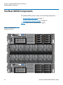
StorNext M660 Hardware Guide 6-67639-01 Rev A StorNext M660 Hardware Guide, 6-67639-01 Rev A June 2012, Product of USA. Quantum, the Quantum logo, DLT, DLTtape, the DLTtape logo, Scalar, StorNext, the DLT logo, DXi, GoVault, SDLT, StorageCare, Super DLTtape, and SuperLoader are registered trademarks of Quantum Corporation in the U.S. and other countries. Protected by Pending and Issued U.S. and Foreign Patents, including U.S. Patent No. 5,990,810. LTO and Ultrium are trademarks of HP, IBM, and Quantum in the U.S. and other countries. All other trademarks are the property of their respective companies. Specifications are subject to change without notice. StorNext uses the following components, which are copyrighted by their respective entities: ACSAPI, copyright © Storage Technology Corporation; Java, copyright Oracle Corporation; LibICE, LibSM, LibXau, LibXdmcp, LibXext, LibXi copyright The Open Group; LibX11 copyright The Open Group, MIT, Silicon Graphics, and the Regents of the University of California, and copyright (C) 1994-2002 The XFree86 Project, Inc. All Rights Reserved. And copyright (c) 1996 NVIDIA, Corp. NVIDIA design patents pending in the U.S. and foreign countries.; Libxml2 and LibXdmcp, copyright MIT; Linter, copyright © Relex Software Corporation; Ncurses, copyright © 1997-2009,2010 by Thomas E. Dickey <[email protected]>. All Rights Reserved.; TCL/TK, copyright © Sun Microsystems and the Regents of the University of California; TinyXML, copyright (c) 2000 -- 2002 by Lee Thomason and Yves Berquin; vixie-cron: copyright Internet Systems Consortium (ISC); Wxp-tdi.h, copyright © Microsoft Corporation; Zlib, copyright © 1995-2010 Jean-loup Gailly and Mark Adler without notice. ii Quantum StorNext M660 Hardware Guide Contents Chapter 1 Introduction 1 About the StorNext M660 Hardware . . . . . . . . . . . . . . . . . . . . 1 About StorNext . . . . . . . . . . . . . . . . . . . . . . . . . . . . . . . . . . . . . 2 About StorNext M660 Licensing . . . . . . . . . . . . . . . . . . . . . . . . 3 About StorNext Features. . . . . . . . . . . . . . . . . . . . . . . . . . . . . . 3 Purpose of This Guide . . . . . . . . . . . . . . . . . . . . . . . . . . . . . . . . . . . . . . 4 How This Guide is Organized . . . . . . . . . . . . . . . . . . . . . . . . . . 4 Notes, Cautions, and Warnings. . . . . . . . . . . . . . . . . . . . . . . . . 4 Document Conventions . . . . . . . . . . . . . . . . . . . . . . . . . . . . . . 5 Supported Internet Browsers. . . . . . . . . . . . . . . . . . . . . . . . . . . . . . . . . 5 Product Safety Statements . . . . . . . . . . . . . . . . . . . . . . . . . . . . . . . . . . 6 Chapter 2 StorNext M660 Hardware Overview 9 StorNext M660 Components . . . . . . . . . . . . . . . . . . . . . . . . . . . . . . . . 10 StorNext M660 MDC Nodes . . . . . . . . . . . . . . . . . . . . . . . . . . 11 StorNext M660 Metadata Storage . . . . . . . . . . . . . . . . . . . . . 19 StorNext M660 Connectivity . . . . . . . . . . . . . . . . . . . . . . . . . . . . . . . . 29 StorNext M660 Power. . . . . . . . . . . . . . . . . . . . . . . . . . . . . . . 29 StorNext M660 SAN . . . . . . . . . . . . . . . . . . . . . . . . . . . . . . . . 30 StorNext M660 LAN . . . . . . . . . . . . . . . . . . . . . . . . . . . . . . . . 32 Relocating the StorNext M660 System . . . . . . . . . . . . . . . . . . . . . . . . 35 Quantum StorNext M660 Hardware Guide iii Contents Chapter 3 StorNext M660 Basic Operations 37 StorNext M660 Operations . . . . . . . . . . . . . . . . . . . . . . . . . . . . . . . . . 38 Powering On the StorNext M660 System . . . . . . . . . . . . . . . . 38 Shutting Down the StorNext M660 System. . . . . . . . . . . . . . . 39 Locating the System Serial Number . . . . . . . . . . . . . . . . . . . . 40 Basic StorNext Operations . . . . . . . . . . . . . . . . . . . . . . . . . . . . . . . . . . 41 iv Quantum StorNext M660 Hardware Guide Figures Figure 1 StorNext M660 Components (Front). . . . . . . . . . . . . . . . . 10 Figure 2 M660 MDC Node – Front View . . . . . . . . . . . . . . . . . . . . . 11 Figure 3 M660 MDC Node – Hard-Drive Indicator Patterns . . . . . . 13 Figure 4 M661 MDC Node – Rear View . . . . . . . . . . . . . . . . . . . . . 15 Figure 5 M662 MDC Node – Rear View . . . . . . . . . . . . . . . . . . . . . 15 Figure 6 MDC Node – NIC Indicators . . . . . . . . . . . . . . . . . . . . . . . 17 Figure 7 MDC Node - Power Supply Indicator Codes . . . . . . . . . . . 18 Figure 8 StorNext M660 Metadata Array – Front View . . . . . . . . . . 20 Figure 9 Metadata Array – Rear View . . . . . . . . . . . . . . . . . . . . . . . 21 Figure 10 The Metadata Array Controller Connectors and LEDs . . . . 22 Figure 11 StorNext M660 Metadata Array Unit – Front View . . . . . . 26 Figure 12 Metadata Expansion Unit – Rear View . . . . . . . . . . . . . . . 27 Figure 13 Metadata Expansion Unit ESM Canister . . . . . . . . . . . . . . 28 Figure 14 StorNext M660 Power Connections . . . . . . . . . . . . . . . . . 30 Figure 15 StorNext M660 SAN Cabling. . . . . . . . . . . . . . . . . . . . . . . 31 Figure 16 StorNext M661 Network Ports . . . . . . . . . . . . . . . . . . . . . 32 Figure 17 StorNext M662 Network Ports . . . . . . . . . . . . . . . . . . . . . 34 Figure 18 StorNext M660 Power-On Sequence. . . . . . . . . . . . . . . . . 39 Quantum StorNext M660 Hardware Guide v Figures vi Quantum StorNext M660 Hardware Guide Tables Table 1 StorNext M660 MDC Node – Front View Indicators and Buttons . . . . . . . . . . . . . . . . . . . . . . . . . . . . . . . . . . . 11 Table 2 M660 MDC Node – Hard-Drive Activity and Status Indicators. . . . . . . . . . . . . . . . . . . . . . . . . . . . . . . . 14 Table 3 StorNext M660 Models – Rear Panel Features and Indicators. . . . . . . . . . . . . . . . . . . . . . . . . . . . . . . . . . 16 Table 4 MDC Node - NIC Indicator Codes . . . . . . . . . . . . . . . . . . . 17 Table 5 Metadata Array – Left End Cap LEDs . . . . . . . . . . . . . . . . 20 Table 6 Metadata Array – Rear Panel Features and Indicators . . . . 22 Table 7 Metadata Array – LED Locations and Behavior . . . . . . . . . 24 Table 8 Metadata Expansion Unit – Rear Panel Features and Indicators. . . . . . . . . . . . . . . . . . . . . . . . . . . . . . . . . . 28 Table 9 StorNext M661 Network Configuration . . . . . . . . . . . . . . 33 Table 10 StorNext M662 Network Configuration . . . . . . . . . . . . . . 35 Quantum StorNext M660 Hardware Guide vii Tables viii Quantum StorNext M660 Hardware Guide Chapter 1 Introduction Combining industry-proven Quantum hardware and StorNext software, the StorNext M660 Metadata Appliance is an integrated system designed to optimize performance in an easy-to-use configuration. About the StorNext M660 Hardware Note: At times this guide uses the term StorNext M660 as a generic term that applies to both the StorNext M661 and the StorNext M662. Quantum’s StorNext M660 is an all-in-one appliance combining the powerful file sharing capabilities of StorNext with pre-configured hardware. The system is powered by a HA pair of metadata controllers (MDC) nodes configured for resiliency. The appliance offers two models: • The StorNext M661 features 11 1GbE configurable Ethernet ports per node. • The StorNext M662 features two 10 GbE and seven 1 GbE configurable Ethernet ports per node. MDCs coordinate SAN file access across clients. Additionally, the standby node can be used as a distributed data mover (DDM), or both MDC nodes can be used as DLC gateways. Quantum StorNext M660 Hardware Guide 1 Chapter 1: Introduction About StorNext StorNext is data management software that enables customers to complete projects faster, and confidently store more data at a lower cost. Used in the world's most demanding environments, StorNext is the standard for high-performance shared workflow operations and multitier archives. StorNext consists of two components: StorNext File System (SNFS), which is high-performance data sharing software, and StorNext Storage Manager (SNSM), an intelligent, policy-based data mover. StorNext File System streamlines processes and facilitates faster job completion by enabling multiple business applications to work from a single, consolidated data set. Using SNFS, applications running on different operating systems (Windows, Linux, Solaris, HP-UX, AIX, and Mac OS X) can simultaneously access and modify files on a common, high-speed SAN storage pool. This centralized storage solution eliminates slow LAN-based file transfers between workstations, and dramatically reduces delays caused by single-server failures. In high availability (HA) configurations, a redundant server is available to access files, pick up the processing requirements of a failed system, and carry on processing. StorNext Storage Manager enhances the StorNext solution by reducing the cost of long-term data retention, without sacrificing accessibility. SNSM sits on top of SNFS and uses intelligent data movers to transparently locate data on multiple tiers of storage. This enables customers to store more files at a lower cost, without having to reconfigure applications to retrieve data from disparate locations. Instead, applications continue to access files normally, and SNSM automatically handles data access – regardless of where a given file resides. As data movement occurs, SNSM also performs a variety of data protection services to guarantee that data is safeguarded both on site and off site. StorNext AEL Archive combines data management policies with costeffective tape storage to deliver data to users through a simple file system interface. The StorNext AEL includes policy-based data integrity checking, which ensures that the data in the archive will be ready when it’s needed. StorNext AEL includes a feature called Extended Data Life Management (EDLM) that tests and verifies the media in the archive and provides health reports for all cartridges. 2 Quantum StorNext M660 Hardware Guide Chapter 1: Introduction About StorNext M660 Licensing Separate licenses are required for various StorNext features, as well as to perform an upgrade to a new release. The following features are factory-installed on the system: • StorNext Failover (High Availability): Provides the ability to configure and operate a redundant server that can quickly assume control of the StorNext file systems in the event of certain software, hardware and network failures on the primary server. • File System SAN Clients: Includes 10 customer StorNext SAN clients for any supported OS, including the equivalent of two SAN clients for MDCs Nodes. Additional licenses can be purchased separately. • StorNext Gateway: Allows you to use the StorNext M660 as a clustered pair of distributed LAN Gateways. Note: The StorNext gateway functionality cannot be used while per-client Distributed LAN client licenses are also in use. • Distributed Data Mover (DDM): Includes one license for offloading data movement from the StorNext M660 system. • Maintenance: Is associated with the expiration date of your current service contract, and is required to enable StorNext software upgrades. Refer to the Quantum StorNext M330 and StorNext M660 Optional Software Add-On Licensing Instructions for a description of the types of licenses and procedures for obtaining them. About StorNext Features This guide includes information about StorNext features that may not initially apply to your StorNext M660 system, but that could be pertinent in the future. The initial offering of the StorNext M660 is not designed for deduplication, and the standard StorNext deduplication license is not supported with the StorNext M660. Quantum StorNext M660 Hardware Guide 3 Chapter 1: Introduction Purpose of This Guide Purpose of This Guide This guide describes how to identify and operate the key features of the hardware components of the StorNext M660 system. How This Guide is Organized This guide contains the following chapters: • Chapter 1, Introduction provides an overview of this StorNext M660 Hardware Guide, and also includes document conventions, product safety statements, a list of related documents, and supported Internet browsers. • Chapter 2, StorNext M660 Hardware Overview provides an overview of the StorNext M660 system. • Chapter 3, StorNext M660 Basic Operations provides basic operating instructions for the StorNext M660 system. Notes, Cautions, and Warnings 4 The following table describes important information about Notes, Cautions, and Warnings used throughout this guide. Description Definition Consequences Note: Emphasizes important information related to the main topic. No hazardous or damaging consequences. Caution: Advises you to take or avoid a specified action. Failure to take or avoid this action could result in loss of data or harm to equipment. Warning: Advises you to take or avoid a specified action. Failure to take or avoid this action could result in physical harm to the user or hardware. Quantum StorNext M660 Hardware Guide Chapter 1: Introduction Supported Internet Browsers Document Conventions This guide uses the following document conventions to help you recognize different types of information. Hardware Conventions Conventions Right side of the system — Refers to the right side as you face the component being described. Left side of the system — Refers to the left side as you face the component being described. Software Conventions Conventions Examples For all UNIX-based commands, the # prompt is implied, although it is not shown. TSM_control stop For all UNIX-based commands, words in italic are variables and should be replaced with user-defined values. is the same as # TSM_control stop cvaffinity filename where filename is a variable and should be replaced with a user-defined value. Supported Internet Browsers The Internet browser software is not supplied with the StorNext M660 system; you must obtain and install it independently. The StorNext M660 system supports the following Internet browsers: Quantum StorNext M660 Hardware Guide 5 Chapter 1: Introduction Product Safety Statements Windows • Internet Explorer 7.x, 8.x and 9.x • Firefox 3.x or later Linux • Firefox 1.5 or later Solaris • Firefox 1.5 or later Product Safety Statements Quantum will not be held liable for damage arising from unauthorized use of the product. The user assumes all risk in this aspect. This unit is engineered and manufactured to meet all safety and regulatory requirements. Be aware that improper use may result in bodily injury, damage to the equipment, or interference with other equipment. WARNING: Before operating this product, read all instructions and warnings in this document and in the system, safety, and regulatory guides. 6 Quantum StorNext M660 Hardware Guide Chapter 1: Introduction Product Safety Statements Quantum StorNext M660 Hardware Guide 7 Chapter 1: Introduction Product Safety Statements 8 Quantum StorNext M660 Hardware Guide Chapter 2 StorNext M660 Hardware Overview This chapter describes the following: • StorNext M660 Components on page 10 • StorNext M660 Connectivity on page 29 • Relocating the StorNext M660 System on page 35 Quantum StorNext M660 Hardware Guide 9 Chapter 2 StorNext M660 Hardware Overview StorNext M660 Components StorNext M660 Components The StorNext M660 system consists of the following components: • StorNext M660 MDC Nodes on page 11 • StorNext M660 Metadata Storage on page 19 Figure 1 shows the full StorNext M660 system. Figure 1 StorNext M660 Components (Front) 10 Quantum StorNext M660 Hardware Guide Chapter 2 StorNext M660 Hardware Overview StorNext M660 Components StorNext M660 MDC Nodes The two StorNext M660 MDC Nodes are servers that provide storage and control for the StorNext M660 platform software (host OS and M660 StorNext software). The MDC Nodes contain dual hard drives in a RAID 1configuration, ensuring high availability of the system software. MDC Node - Front View Figure 2 shows, and Table 1 describes the indicators and buttons on the front of the StorNext M660 MDC Node. The two hard drives located on the front of the MDC Node (in drive bays 0 and 1) are used to store the (operating system and M660 StorNext software). Drive bays 2 through 7 are empty, and reserved for Quantum use. Unlabeled indicators, connectors, and buttons are reserved for Quantum Service. For more information, see MDC Node – Hard-Drive Indicator Patterns on page 13. Figure 2 M660 MDC Node – Front View StorNext M660 Platform Software Empty Drive Slots Table 1 StorNext M660 MDC Node – Front View Indicators and Buttons Item Indicators and Buttons 1 Service tag Description The slide-out label panel for the system information including information such as the Service Tag and Express Service Code. Quantum StorNext M660 Hardware Guide 11 Chapter 2 StorNext M660 Hardware Overview StorNext M660 Components Item Indicators and Buttons Description 2 Power-On Indicator The power-on indicator lights when the system power is on. The power button controls the DC power supply output to the system. When the system bezel is installed, the power button is not accessible. 3 LCD panel The LCD panel shows the system ID, status information, and system error messages. The LCD lights blue during normal system operation. When the system needs attention, the LCD lights amber, and the LCD panel displays an error code, followed by descriptive text. Note: Note: If the system is connected to AC power and an error has been detected, the LCD lights amber, regardless of whether the system has been powered on. 12 Quantum StorNext M660 Hardware Guide Chapter 2 StorNext M660 Hardware Overview StorNext M660 Components MDC Node – Hard-Drive Indicator Patterns Figure 3 shows, and Table 2 on page 14 describes the StorNext M660 MDC Node hard-drive indicator patterns (. Figure 3 M660 MDC Node – Hard-Drive Indicator Patterns 1 2 1 Hard-drive activity indicator (green) 2 Hard-drive status indicator (green and amber) Quantum StorNext M660 Hardware Guide 13 Chapter 2 StorNext M660 Hardware Overview StorNext M660 Components Table 2 M660 MDC Node – Hard-Drive Activity and Status Indicators Drive-Status Indicator Pattern (RAID Only) Condition Blinks green two times per second Identify drive/preparing for removal. Off Drive ready for insertion or removal. When system power is applied, the drive status indicator remains off until all hard drives are initialized. Drives are not ready for insertion or removal during this time. Blinks green, amber, and off Drive-predicted failure. Blinks amber four times per second Drive failed Blinks green slowly Drive rebuilding Steady green Drive online 14 Quantum StorNext M660 Hardware Guide Chapter 2 StorNext M660 Hardware Overview StorNext M660 Components MDC Node – Rear View The back of the StorNext M660 MDC Nodes have a series of indicators, connectors, and buttons. Unlabeled indicators, connectors, and buttons are reserved for Quantum Service. Figure 4 shows the rear indicators, connectors, and buttons of the StorNext M661node. Figure 4 M661 MDC Node – Rear View Figure 5 shows the rear indicators, connectors and buttons of the StorNext M662 node. Figure 5 M662 MDC Node – Rear View Quantum StorNext M660 Hardware Guide 15 Chapter 2 StorNext M660 Hardware Overview StorNext M660 Components Use Table 3 for information on the labeled components. Table 3 StorNext M660 Models – Rear Panel Features and Indicators Item 1 Indicator, Connector and Button PCIe slot 1 Icon Description StorNext M661: 4-port 1 GbE Ethernet HBA StorNext M662: 2-port 10 GbE Ethernet HBA 16 2 PCIe slot 2 StorNext M661/M662: 4-port 1 GbE Ethernet HBA (M661 and M662) 3 PCIe slot 3 4-port 8Gb FC SAS HBA 4 PCIe slot 4 2-port 6Gb SAS HBA 5 iDRAC6 Enterprise port Reserved for Quantum Service 6 Ethernet Service port Reserved for Quantum Service 7 Ethernet connectors (3 configurable ports) Integrated 10/100/1000 NIC ports 8 Power supply 1 (PS1) 870-W power supply 9 Power supply 2 (PS2) 870-W power supply Quantum StorNext M660 Hardware Guide Chapter 2 StorNext M660 Hardware Overview StorNext M660 Components MDC Node – NIC Indicator Codes Figure 6 shows, and Table 4 describes the StorNext M660 MDC Node NIC indicator codes. Figure 6 MDC Node – NIC Indicators 1 2 1 Link indicator 2 Activity indicator Table 4 MDC Node - NIC Indicator Codes Indicator Status Indicator Code Link and activity indicators are off. The NIC is not connected to the network. Link indicator is green. The NIC is connected to a valid network link at 1000 Mbps. Link indicator is amber. The NIC is connected to a valid network link at 10/100 Mbps. Activity indicator is blinking green. Network data is being sent or received. Quantum StorNext M660 Hardware Guide 17 Chapter 2 StorNext M660 Hardware Overview StorNext M660 Components MDC Node – Power Supply Indicator Codes This section describes the StorNext M660 MDC Node power supply indicator codes (see Figure 7). Figure 7 MDC Node - Power Supply Indicator Codes 1 Link indicator The power supplies have indicators that show if power is present, or if a power fault has occurred. • Not lit — AC power is not connected. • Green — In standby mode, a green light indicates that a valid AC source is connected to the power supply, and that the power supply is operational. When the system is on, a green light also indicates that the power supply is providing DC power to the system. • Amber — Indicates a problem with the power supply. • Alternating green and amber — When hot-adding a power supply, this indicates that the power supply is mismatched with the other power supply (a high-output power supply and an energy smart power supply are installed in the same system). Replace the power supply that has the flashing indicator with a power supply that matches the capacity of the other installed power supply. 18 Quantum StorNext M660 Hardware Guide Chapter 2 StorNext M660 Hardware Overview StorNext M660 Components StorNext M660 Metadata Storage The StorNext M660 features the following metadata storage modules: • StorNext M660 Metadata Array • Metadata Expansion Unit on page 26 StorNext M660 Metadata Array The StorNext M660 Metadata Array features a fully populated 24-drive 2U storage enclosure. The first two drives are global hot spares. The next six are configured into three 1+1 RAID-1 mirrors. These mirrored sets are split into two stripe groups (SGs): SG0 combines three 12-GB LUNs into the metadata and journal for the shared file system. SG1 combines three 888-GB LUNs into the shared HA file system, and includes the StorNext Storage Manager database. The hard drives are supplied in hot-swappable drive carriers that fit in the hard-drive bays. The StorNext M660 Metadata Array has a series of indicators and buttons located on the front and back of the array: • Metadata Array – Front View • Metadata Array – Rear View on page 21 Metadata Array – Front View The front of the StorNext M660 Metadata Array contains the left end cap, which contains the drive tray LEDs; the right end cap; and the drives (see Figure 8 and Table 5 on page 20). Quantum StorNext M660 Hardware Guide 19 Chapter 2 StorNext M660 Hardware Overview StorNext M660 Components Figure 8 StorNext M660 Metadata Array – Front View Global Hot Spares 3 x 1+1 RAID 1 8 x 1+1 RAID 1 Table 5 Metadata Array – Left End Cap LEDs Item LED Description Color On Off 1 Drive Tray Locate White Identifies a drive tray that you are trying to find. Normal status 2 Service Action Required Amber A component within the drive tray needs attention. Normal status 3 Drive Enclosure OverTemperature Amber The temperature of the drive tray has reached an unsafe level. Normal status 4 Power Green Power is present. Power is not present. 5 Standby Power Green The drive tray is in Standby Power mode. The drive tray is not in Standby Power mode. 20 Icon Quantum StorNext M660 Hardware Guide Chapter 2 StorNext M660 Hardware Overview StorNext M660 Components Metadata Array – Rear View The StorNext M660 Metadata Array contains dual controller canisters for host connectivity and redundancy (see Figure 9). Figure 9 Metadata Array – Rear View Port 1 Lnk Port 2 ID/Diag ID/Di Quantum StorNext M660 Hardware Guide Lnk Port 1 Lnk Port 2 Lnk ID/Diag 21 Chapter 2 StorNext M660 Hardware Overview StorNext M660 Components Figure 10 shows, and Table 6 describes the storage controller’s connectors, displays and LEDs. Unlabeled connectors are reserved for Quantum Service. Figure 10 The Metadata Array Controller Connectors and LEDs Port 1 Lnk Port 2 Lnk ID/Diag Table 6 Metadata Array – Rear Panel Features and Indicators Item 1 Host Fault LED 2 Host Active LED 3 Host Port Connector 1 (SFF-8088) 4 Host Port Connector 2 (SFF-8088) 5 ESM Expansion Fault LED 6 ESM Expansion Active LED 7 Expansion Port Connector (SFF-8088) 8 Battery Service Action Required LED 9 Battery Charging LED 10 22 Description Controller Service Action Allowed LED Quantum StorNext M660 Hardware Guide Chapter 2 StorNext M660 Hardware Overview StorNext M660 Components Item Description 11 Controller Service Action Required LED 12 Cache Active LED 13 Seven-Segment Displays Quantum StorNext M660 Hardware Guide 23 Chapter 2 StorNext M660 Hardware Overview StorNext M660 Components Metadata Array — General LED Behavior For more information about the Metadata Array LED locations and general behavior, see Table 7. Table 7 Metadata Array – LED Locations and Behavior LED Power Icon Location General Behavior • Drive enclosure On – Power is applied to the drive tray or the canister. • Controller canister • Power-fan canister Off – Power is not applied to the drive tray or the canister. Locate • Front bezel on the drive tray On or blinking – Indicates the drive tray that you are trying to find. OverTemperature • Front bezel on the drive tray On – The temperature of the drive tray has reached an unsafe condition. Off – The temperature of the drive tray is within operational range. Standby Power • Front bezel on the drive tray On – The drive tray is in Standby mode, and the main DC power is off. Off – The drive tray is not in Standby mode, and the main DC power is on. Service Action Allowed • Controller canister • Power-fan canister • Drive On – It is safe to remove the Controller canister, the power-fan canister, or the drive. Off – Do not remove the Controller canister, the power-fan canister, or the drive. Note: The drive has an LED, but no symbol. 24 Quantum StorNext M660 Hardware Guide Chapter 2 StorNext M660 Hardware Overview StorNext M660 Components LED Icon Service Action Required (Fault) Location General Behavior • Controller canister On – When the drive tray LED is on, a component within the drive tray needs attention. • Power-fan canister • Drive On – The Controller canister, the power-fan canister, or the drive needs attention. Off – The Controller canister, the power-fan canister, and the drive are operating normally. Note: The drive has an LED, but no symbol. AC Power DC Power • Controller canister On – AC power is present. • Power-fan canister Off – AC power is not present. • Power-fan canister On – Regulated DC power from the power-fan canister is present. Off – Regulated DC power from the power-fan canister is not present. • Controller canister Link Service Action Required (Fault) Link Up On – The cable is attached, and at least one lane has a link-up status, but one lane has a link-down status. Off – The cable is not attached, and all lanes have a link-up status, or the cable is attached, and all lanes have a linkdown status. Two LEDs above each expansion connector • Controller canister Quantum StorNext M660 Hardware Guide On – The cable is attached, and at least one lane has a link-up status. Off – The cable is not attached, or the cable is attached and all lanes have a linkdown status. 25 Chapter 2 StorNext M660 Hardware Overview StorNext M660 Components Metadata Expansion Unit The StorNext M660 Metadata Expansion Unit features a fully populated 24-drive 2U storage enclosure. The first two drives are global hot spares. The next six are configured into three 1+1 RAID-1 mirrors. These mirrored sets are split into two stripe groups (SGs): SG0 combines three 12-GB LUNs into the metadata and journal for the shared file system. SG1 combines three 888-GB LUNs into the shared HA file system. The hard drives are supplied in hot-swappable drive carriers that fit in the hard-drive bays. The StorNext M660 Metadata Expansion Unit has a series of indicators and buttons located on the front and back of the array: • Metadata Expansion Unit – Front View • Metadata Expansion Unit – Rear View on page 27 Metadata Expansion Unit – Front View The front of the StorNext M660 Metadata Expansion Unit contains the left end cap, which contains the drive tray LEDs; the right end cap; and the drives (see Figure 11, and Table 5 on page 20). Figure 11 StorNext M660 Metadata Array Unit – Front View Global Hot Spares 26 3 x 1+1 RAID 1 8 x 1+1 RAID 1 Quantum StorNext M660 Hardware Guide Chapter 2 StorNext M660 Hardware Overview StorNext M660 Components Metadata Expansion Unit – Enclosure Tray LEDs The enclosure LEDs on the front of the unit are identical to those on the front of the Metadata Array. To monitor the current status pertaining to the enclosure and the components within the enclosure, refer back to Figure 9 on page 21 and Table 5 on page 20. Metadata Expansion Unit – Rear View The StorNext M660 Metadata Expansion Unit contains dual environmental service monitor (ESM) canisters for connectivity to the Metadata Array. Each ESM features LED indicators and connectors. Figure 12 shows the location of the ESMs. Figure 12 Metadata Expansion Unit – Rear View P t1 Port ID/Diag Quantum StorNext M660 Hardware Guide P t1 Port ID/Diag g 27 Chapter 2 StorNext M660 Hardware Overview StorNext M660 Components Figure 13 shows the location of LEDs and SAS connectors. Figure 13 Metadata Expansion Unit ESM Canister . Port 1 ID/Diag Table 6 describes the ESM connectors, displays, and LEDs. Unlabeled connectors are reserved for Quantum Service. Table 8 Metadata Expansion Unit – Rear Panel Features and Indicators 28 Item Description 1 Host Link 1 Fault LED 2 Host Link 2 Fault LED 3 SAS IN Connector 4 SAS IN Connector 5 ESM Expansion Fault LED 6 ESM Expansion Active LED 7 SAS Expansion Connector 8 Controller A Service Action Allowed LED 9 Controller A Service Action Required LED 10 Cache Active LED 11 Seven-Segment Displays Quantum StorNext M660 Hardware Guide Chapter 2 StorNext M660 Hardware Overview StorNext M660 Connectivity Metadata Expansion Unit — General LED Behavior The drive enclosure is the same as the Metadata Array. For more information about the Metadata Expansion Unit LED locations and general behavior, refer back to Table 7 on page 24. StorNext M660 Connectivity This section covers: • StorNext M660 Power • StorNext M660 SAN on page 30 • StorNext M660 LAN on page 32 StorNext M660 Power Connect the power cables for each component into an available power outlet (see Figure 14 on page 30). Quantum recommends attaching the primary and secondary power connections to alternate power sources for resiliency. Quantum also recommends that one of these power sources be an uninterruptible power source, such as battery backup or generator, or be connected to redundant AC power supplies. Quantum StorNext M660 Hardware Guide 29 Chapter 2 StorNext M660 Hardware Overview StorNext M660 Connectivity Primary Power Supply Port 1 Lnk Port 2 Lnk Port 1 Primary Power Supply Lnk Port 2 Lnk Secondary Power Supply Port 1 ID/Diag Port 1 ID/Diag Primary Power Supply StorNext M660 SAN Secondary Power Supply ID/Diag ID/Diag MDC Node 2 Metadata Expansion Metadata Array MDC Node 1 Figure 14 StorNext M660 Power Connections Secondary Power Supply Primary Power Supply Secondary Power Supply Each StorNext M660 MDC node contains one 4-port 8Gb FC host bus adapter (HBA) card in PCIe expansion slot 3. Fibre Channel Zoning The StorNext M660 includes a single, quad-port Fibre Channel HBA and supports dual-port tape drives and libraries. StorNext clients should not be zoned to access the tape drives-libraries unless they are acting as a Distributed Data Mover. 30 Quantum StorNext M660 Hardware Guide Chapter 2 StorNext M660 Hardware Overview StorNext M660 Connectivity Separate Fibre Channel zoning is required for tape and disk. If the system has a tape library, use FC ports 1 and 2 for disk, and FC ports 3 and 4 for tape. The actual zoning configuration for these devices is dependent on variables such as the Fibre Channel switch vendor, the WWPN of the HBA ports, and the external hardware. Connect the FC host ports to your SAN as shown in Figure 15 on page 31. MDC Node 1 Figure 15 StorNext M660 SAN Cabling Metadata Array MDC Node 2 Metadata Expansion DISK SAN TAPE SAN RAID Primary Storage Quantum StorNext M660 Hardware Guide RAID Tapes Storage Disk Tertiary Storage 31 Chapter 2 StorNext M660 Hardware Overview StorNext M660 Connectivity StorNext M660 LAN The number of customer-facing network ports depends on the model type. By default, each M660 model ships with two bonded network interfaces: Bond 0 and Bond 1. All ports are customer-configurable. Instructions for changing the default configuration are located in the “Step 3: System (StorNext M660 and StorNext M330 Only)” section of the StorNext 4.2.2.0.1 User’s Guide. Figure 16 shows the 11 1GbE customer-facing Ethernet ports on the StorNext M661. Figure 16 StorNext M661 Network Ports The default StorNext M661 network interface configuration is as follows: • Two interfaces, Eth2 and Eth3, are bonded together by default into bond0 for the Metadata network. This bond can be broken in the GUI and the ervice menu. When not bonded, Eth2 will be configured as a standalone port, and Eth3 will be de-configured and not used by the system. • Two interfaces, Eth1 and Eth4, are bonded together into bond1 for GUI/management. This bond can be broken in the GUI and the Service Menu. When not bonded, Eth1 will be configured as a standalone port and Eth4 will be de-configured and not used by the system. • The remaining seven ports can be configured through the GUI in various combinations and bonds for gateway port access. 32 Quantum StorNext M660 Hardware Guide Chapter 2 StorNext M660 Hardware Overview StorNext M660 Connectivity Table 9 identifies the logical port configuration, port function and default bonding for the StorNext M661. Table 9 StorNext M661 Network Configuration Ethernet Port Number Logical Ethernet Port Number Physical Port Location D N/A iDRAC Port S eth0 Integrated Port 1 1 eth1 Integrated Port 2 2 eth2 Integrated Port 3 3 eth3 Integrated Port 4 4 eth4 Slot 2, Port 1 5 eth5 Slot 2, Port 2 6 eth6 Slot 2, Port 3 7 eth7 Slot 2, Port 4 8 eth8 Slot 1, Port 1 9 eth9 Slot 1, Port 2 10 eth10 Slot 1, Port 3 11 eth11 Slot 1, Port 4 Quantum StorNext M660 Hardware Guide Port Function Bond Service N/A GUI and Management (Configurable from Service Menu) Bond 1 When not bonded, eth1 is usable and eth4 is not usable Metadata (Configurable from Service Menu) When not bonded, eth2 is usable and eth3 is not usable Bond 0 When not bonded, eth3 is not used GUI and Management Bond 1 (Configurable from Service Menu) When not bonded, eth4 is not used Gateway User Configurable from GUI 33 Chapter 2 StorNext M660 Hardware Overview StorNext M660 Connectivity Figure 17 shows the two 10GbE and seven 1GbE customer-facing Ethernet ports on the StorNext M662. Figure 17 StorNext M662 Network Ports The default StorNext M662 network interface configuration is as follows: • Two interfaces, Eth2 and Eth3, bonded together into bond0 for the Metadata network. This bond can be broken in the GUI and the service menu. When not bonded, Eth2 will be configured as a standalone port and Eth3 will be de-configured and not used by the system. • Two interfaces, Eth1 and Eth4, are bonded together into bond1 for GUI/management. This bond can be broken in the GUI and the service menu. When not bonded, Eth1 will be configured as a standalone port and Eth4 will be de-configured and not used by the system. • The remaining five ports can be configured through the GUI in various combinations and bonds for gateway port access. 34 Quantum StorNext M660 Hardware Guide Chapter 2 StorNext M660 Hardware Overview Relocating the StorNext M660 System Table 10 identifies the logical port configuration, port function and default bonding for the StorNext M662. Table 10 StorNext M662 Network Configuration Ethernet Port Number Logical Ethernet Port Number Physical Port Location D N/A iDRAC Port S eth0 Integrated Port 1 1 eth1 Integrated Port 2 2 eth2 Integrated Port 3 3 eth3 Integrated Port 4 4 eth4 Slot 2, Port 1 5 eth5 Slot 2, Port 2 6 eth6 Slot 2, Port 3 7 eth7 Slot 2, Port 4 8 eth8 Slot 1, Port 1 (10 GbE) 9 eth9 Slot 1, Port 2 (10 GbE) Port Function Bond Service N/A GUI and Management (Configurable from Service Menu) Bond 1 When not bonded, eth1 is usable and eth4 is not usable Metadata (Configurable from Service Menu) When not bonded, eth2 is usable and eth3 is not usable Bond 0 When not bonded, eth3 is not used GUI and Management Bond 1 (Configurable from Service Menu) When not bonded, eth4 is not used Gateway User Configurable from GUI Relocating the StorNext M660 System If you ever need to relocate the StorNext M660 system to a different location, please contact Quantum Customer Support for additional information. The StorNext M660 system must be relocated by a qualified Quantum field service engineer. Quantum StorNext M660 Hardware Guide 35 Chapter 2 StorNext M660 Hardware Overview Relocating the StorNext M660 System 36 Quantum StorNext M660 Hardware Guide Chapter 3 StorNext M660 Basic Operations This chapter describes the following StorNext M660 basic system operations: • StorNext M660 Operations on page 38 • Basic StorNext Operations on page 41 Quantum StorNext M660 Hardware Guide 37 Chapter 3 StorNext M660 Basic Operations StorNext M660 Operations StorNext M660 Operations The StorNext M660 system consists of the following components: • Powering On the StorNext M660 System on page 38 • Shutting Down the StorNext M660 System on page 39 • Locating the System Serial Number on page 40 Powering On the StorNext M660 System Figure 18 on page 39 illustrates the location of the power switches, and the specific order to follow when powering on in the StorNext M660 components. Verify that all power switches on every component are OFF. 1 Turn on both power switches on the back of the Metadata Expansion Unit, if available. Callout number 1 in Figure 18 on page 39 shows the location of the power switches. Note: The Metadata Expansion Unit drive LEDs should all be green before you power up the Metadata Array. The sevensegment display, which displays on both controllers, should show 0 before powering up the Metadata Array. 2 Turn on both power switches on the back of the Metadata Array. Callout number 2 in Figure 18 on page 39 shows the location of the power switches. Note: The Metadata Array module drive LEDs should all be green before you power up the MDC Nodes. The seven-segment indicator, which displays on both controllers, should show 85 before powering up the MDC Nodes. 3 Turn on the power switch on each of the MDC Node.Callout number 3 in Figure 18 on page 39 shows the location of the power switch. 38 Quantum StorNext M660 Hardware Guide Chapter 3 StorNext M660 Basic Operations StorNext M660 Operations Port 1 Lnk Port 2 ID/Diag Lnk Port 1 Lnk Port 2 ID/Diag Port 1 ID/Diag Lnk Port 1 ID/Diag MDC Node 2 (Front) Metadata Expansion Metadata Array MDC Node 1 (Front) Figure 18 StorNext M660 Power-On Sequence Shutting Down the StorNext M660 System Follow these steps to cleanly shut down and power off the StorNext M660 system: Note: In the case where both MDC nodes are being used as, 1 Halt all I/O access to SAN and/or LAN clients. Quantum StorNext M660 Hardware Guide 39 Chapter 3 StorNext M660 Basic Operations StorNext M660 Operations 2 For each SAN and/or LAN client, unmount and/or unshare the file systems. Refer to that client’s operating system administrator’s guide for instructions. 3 Open an ssh connection to the secondary MDC Node, and log in as the stornext user. 4 Enter the password for the stornext user account. (Until changed, the default password is password). 5 Run the sudo rootsh command. 6 Enter the password for the stornext user account a second time. 7 Run the /sbin/poweroff command. Both the operating system and the StorNext software are gracefully shut down, and then the system powers off. 8 Open an ssh connection to the primary MDC Node, and log in as the stornext user. 9 Enter the password for the stornext user account. (Until changed, the default password is password). 10 Run the sudo rootsh command. 11 Enter the password for the stornext user account a second time. 12 Run the /sbin/poweroff command. Both the operating system and the StorNext software are gracefully shut down, and then the system powers off. 13 Turn off the Metadata Array module power switches. 14 Turn off the Metadata Expansion Unit power switches. Locating the System Serial Number When contacting customer support, you will be asked for the StorNext M660 system serial number To locate the system serial number from the StorNext M660 GUI refer to the information about the Help Menu in the “StorNext GUI Overview” section of the StorNext 4.2.2.0.1 User’s Guide. The system serial number is also located in a clear sleeve in the back of each MDC Node, and on the back of the Metadata Array and Metadata Expansion Unit. The system serial number begins with the characters CX and contains the characters CKB in the number, for example, CX1234CKB45678. 40 Quantum StorNext M660 Hardware Guide Chapter 3 StorNext M660 Basic Operations Basic StorNext Operations Basic StorNext Operations You can perform some basic operations from the StorNext M660 StorNext GUI: • For information on how to monitor the hardware components for both MDC nodes, refer to the “The Hardware Status Report” section of the StorNext 4.2.2.0.1 User’s Guide (6-67370-05 Rev A). • For instructions on how to capture system state logs and support bundles, refer to the “The Capture State Function” section of the StorNext 4.2.2.0.1 User’s Guide. • For instructions on how to capture DSET logs, refer to the “Capture DSET” section of the StorNext 4.2.2.0.1 User’s Guide. • For instructions on how to perform a firmware upgrade on your HA system and upgrade StorNext, refer to the “Update Firmware” section of the StorNext 4.2.2.0.1 User’s Guide. • For information on changing the network configuration, refer to the “Step 3: System (StorNext M660 and StorNext M330 Only)” section of the StorNext 4.2.2.0.1 User’s Guide. • For information on Gateway Reporting, refer to the “Reports” section of the StorNext 4.2.2.0.1 User’s Guide. • For information on setting up a distributed data mover (DDM), refer to “Distributed Data Mover (DDM)” section of the StorNext 4.2.2.0.1 User’s Guide. • For information on StorNext Advanced Reporting, refer to the StorNext Advanced Reporting User’s Guide. The StorNext 4.2.2.0.1 User’s Guide also contains chapters such as these, which you will find useful: • StorNext File System Tasks • StorNext Storage Manager Tasks • StorNext Reports • Service Menu Functions Quantum StorNext M660 Hardware Guide 41 Chapter 3 StorNext M660 Basic Operations Basic StorNext Operations 42 Quantum StorNext M660 Hardware Guide