1
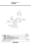
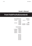
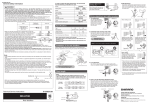
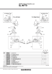
ENGLISH
ENGLISH
ENGLISH
Contents
1. PRODUCT ELEMENTS.......................... 3
Teaching ...................................11
Settings ....................................12
2. INTRODUCTION ................................ 4
3. INSTALL POWER SENSOR MAIN UNIT ........ 5
Install Cadence Magnet ................... 6
4. INSTALL BATTERY CASE ...................... 7
5. INSTALL CHAIN SPEED SENSOR .............. 8
6. VERIFICATION OF THE SENSOR
INSTALLATIONS .............................. 10
7. POWER SETTINGS FOR CYCLING
COMPUTER ................................... 11
8. CUSTOMER SERVICE INFORMATION ......... 14
Care and Maintenance ...................14
Power Output Sensor Battery ............15
Frequently Asked Questions .............16
Technical Specifications .................17
Limited International Polar Guarantee..18
Disclaimer .................................20
ENGLISH
1. PRODUCT ELEMENTS
Product Elements 3
ENGLISH
2. INTRODUCTION
The drive force of a bike is transmitted entirely
through the chain, allowing the cycling computer
to calculate watts very accurately. The system
works by measuring two key factors:
•
•
Chain Tension - measured with the Power Output
Sensor main unit
Chain Speed - measured with the Chain Speed
Sensor
Together with the Polar Cycling Computer, Polar
Power Output Sensor measures
•
•
•
•
Actual, average and maximum Power values,
Left/Right Balance (distribution of power
between left and right legs),
Pedaling Index (how even the power is
distributed during a crank arm rotation), and
Cadence
4 Introduction
For training purposes, Power Output Sensor
provides much more precision than heart rate
measurement and perceived exertion. Power
measurements also have a number of other uses,
including bike positions and determining
efficiency at different cadences among others.
Polar Power Output Sensor is suitable only for
road bikes, ridden on tarmac. It is not suitable for
mountain bikes or bikes with very complex rear
stays.
For more instructions on how best to benefit from
the Power Output Sensor, please see the Polar
Cycling Computer user manual.
ENGLISH
3. INSTALL POWER SENSOR MAIN UNIT
To install the Power Output Sensor, you will need
10 mm wrench, 3 mm Allen key, a chain breaker,
scissors, measuring tape and rubber gloves.
Attach the Power Output Sensor main unit to the
top of the right chain stay, so that the wires are
directed backwards. Position the sensor just on
the top of the chain stay, not leaning to either side
(picture 1).
Disconnect the electric wires from the main unit
before installing.
Before installing the main unit, measure the span
length as instructed on page 12. The main unit
must be placed in such a way that the dot on the
upper side of the unit (picture 2 a) is exactly in
the middle of the chain stay. The ideal place for
the sensor is as close to the chain as possible
without the chain touching it (about 2mm/0.08”)
in the small/small chainring/cog combination.
Depending on your frame, it may be necessary to
put supporting pieces under the sensor. Note that
there are supporting pieces of three sizes in the
set.
Before attaching the supporting pieces for the
sensors or the magnet to the bicycle, the area in
question should be cleaned and dried thoroughly.
The sensor should be attached directly under the
chain (picture 1). The measurement is most
accurate when the chain runs just over the
sensor's central axis. Make sure that the crank
doesn’t hit the unit when pedaled.
Pass the cable ties through the sensor holes and
around the chain stay. Do not wind them around
the gear cable. Adjust the ties loosely. Do not
tighten the cable ties of the sensor fully before
installing the cadence magnet.
Install Power Sensor Main Unit 5
ENGLISH
Install Cadence Magnet
When you install the cadence magnet, the chain
should be on the largest front chainring. This way
you can make sure that the chain does not touch
the magnet.
Install the cadence magnet inside of the crank
(picture 1 and 2 b). To ensure successful
transmission of cadence signals, the cadence
magnet should pass the "cadence notch" on the
power sensor.
Attach the magnet to the crank arm so that it
passes the sensor closely but does not touch it.
The maximum distance between the power sensor
and the cadence magnet should be 7 mm / 0.3".
Secure the magnet with tape.
Tighten the cable ties around the main unit and
cut off any excess ends.
6 Install Power Sensor Main Unit
ENGLISH
4. INSTALL BATTERY CASE
Attach the battery case to the seat stay, on the
same side of the bike as the power sensor main
unit (picture 3). Pass the cable ties through the
battery case holes and around the seat stay.
Tighten the cable ties and cut off any excess ends.
Also use cable ties to secure the battery case wire
so that it is not hanging loosely.
Choose the place for the Battery Case so that you
can easily take out the battery holder when
changing batteries. For more information, see
Care and Maintenance.
Install Battery Case 7
ENGLISH
5. INSTALL CHAIN SPEED SENSOR
Wind the wire from the power sensor to the chain
speed sensor securely around the rear derailleur
cable, or use cable ties to secure the wire so that
it is not hanging loosely. However, the normal
operation of the rear derailleur must be possible.
Avoid extreme tightening of the wire.
There are three pulley bolts included in the
package. Choose the most suitable bolt to install
on your bike. The table on the following page
includes the most commonly used rear derailleur
types, but the bolts are suitable for many other
types, as well.
Detach the original bolt from the rear derailleur
and replace it with one of the bolts delivered in
the package. Install the chain speed sensor on
bolt and tighten it with a locknut (picture 4). Do
not tighten fully yet.
8 Install Chain Speed Sensor
Check that
• all gears function properly.
• the wire is not too tight or loose with any gear.
• chain speed sensor does not touch the spokes
when the chain is on the largest sprocket.
Tighten the pulley bolt on the rear derailleur.
ENGLISH
Rear derailleur
Pulley bolt
Shimano
Shimano Dura-Ace RD-7700
Ultegra RD-6500
Shimano 105 RD-5500
XTR RD-952
Deore XT RD-M750
Deore LX RD-M570
Shimano
#501030
Shimano
Deore RD-M510
Tiagra RD-4400
Shimano
#501031
Campagnolo
Record 9-speed RD00-RE209
Chorus 9-speed RD00-CH209
Record 10-speed RD00-RE210, RD00-RE210l
Chorus 10-speed RD00-CH210, RD00-CH210l
Racing Triple 9-speed RD00-RA309
Daytona 9-speed RD00-DA209
Daytona Triple 9-speed RD00-DA309
Veloce 9-speed RD99-VL209
Veloce Triple 9-speed RD99-VL309
Mirage RD99-MI209
Mirage Triple RD99-MI309r
Campagnolo
#501032
Install Chain Speed Sensor 9
ENGLISH
6. VERIFICATION OF THE SENSOR INSTALLATIONS
Test the Power sensor and cadence magnet
installation by checking that the green indicator
light flashes in the power sensor when the
cadence magnet passes the "cadence notch" on
the power sensor.
Test the chain speed sensor installation by
checking that the red indicator light flashes in the
power sensor when the chain is rotated.
This is only a testing procedure. The flashing will
not continue after 50 flashes when cycling. If you
want to check this procedure again, you must
pause for one minute during which time the
magnets must not pass the sensors and the chain
must not move.
10 Verification of the Sensor Installations
ENGLISH
7. POWER SETTINGS FOR CYCLING COMPUTER
Teaching
The cycling computer has to be coded to the
power output sensor i.e. taught to receive power
and cadence data. This enables exercising in a
group without interference from other sensors. The
power output sensor and cycling computer in the
same product set have already been synchronized
but teaching is necessary when you start using a
new sensor that has been purchased separately.
All three bike settings can be coded to a different
sensor. The procedure takes only a few seconds.
Install the power sensor to your bike as advised.
Make sure that there are no other power output
sensors nearby (40 m / 130 ft).
Select Settings > Bike > Bike 1/2/3 > Power .
Select On/Off and On to turn the power function
on. Press OK.
•
Select YES to confirm teaching. Start test
drive is displayed. Rotate the crank a few times
to activate the sensor. The flashing red light in
the sensor indicates that the sensor is activated.
Completed is displayed after the teaching has
been finished. The cycling computer is now
ready to receive power data.
•
Select NO to cancel the teaching. The teaching
is cancelled and the cycling computer remains
coded with the previous power sensor used.
To return to Time mode, press and hold the BACK
button.
Power Settings for Cycling Computer 11
ENGLISH
Settings
Set chain weight, chain length and span length
To use the Polar Power output sensor you need to
have the following settings on your cycling
computer. Start by selecting Settings > Bike >
Bike 1/2/3 > Power .
Select Settings > Bike > Bike 1/2/3 > Power >
Turn Power function On/Off
•
Settings
•
On: Teach new sensor? is displayed.
•
•
Select No if you don’t need to change the
sensor.
Confirm with Yes and Start test drive as advised.
When teaching is accomplished, Completed
appears.
Off: Exercise displays updated is displayed.
If you choose to Turn Power function off the Power
data will be removed from all the displays
concerning the Bike in question.
12 Power Settings for Cycling Computer
•
Chain weight (g): If you do not know the default
factory value, remove the chain and weigh it.
Chain length (mm): If you do not know the
factory default value, count the number of loops
and multiply the amount by 12,7 mm.
Span length (mm): measure the distance from
the centre of the rear hub to the centre of the
bottom bracket as shown in the picture 5.
ENGLISH
Examples of chain weights and lenghts:
Shimano Dura-Ace CN-7700 Super narrow HG
weight: 280 g
length: 1473 mm
Shimano Dura-Ace CN-7701
Ultegra CN-HG92, 105 HG72,105 HG73
weight: 280 g
length: 1473 mm
Shimano Sora CN-HG50
weight 335 g
length: 1473 mm
Due to the variation of the measurements, Polar
cannot be held responsible for their validity.
For precise readings, all settings must be as
accurate as possible. Chain length and weight are
directly proportionate to power value. If they have,
for example, 1% error, then the Power Value will
also have this 1% error.
There is no need to re-enter chain length and
weight if links are removed. The system uses
chain density (weight/length). Removing links
from the chain does not affect density.
Campagnolo Record 2000, 10 Speed Chain
weight: 260 g
length: 1473 mm
Campagnolo 10 Speed Chains Chorus, Centaur
weight: 274 g
length: 1473 mm
Campagnolo Veloce, Mirage, and Xenon
weight: 277g
length: 1473 mm
Power Settings for Cycling Computer 13
ENGLISH
8. CUSTOMER SERVICE INFORMATION
Care and Maintenance
Before you start cycling, check that your
handlebars turn normally, brakes and all gears
function properly, the cables are kept out of the
sprockets, all sensors are installed securely and no
surplus wires are hanging loosely. Please note that
installation and maintenance not carried out
according to this manual may result in a serious
accident.
Polar Power Output Sensor is splash proof. This
means that you can use the sensor in the rain and
wash it with water. However, do not wash any part
of the Power Output Sensor with a pressure washer
or immerse any part of the system under water.
14 Customer Service Information
Clean the sensor with a mild soap and water
solution, dry with towel. Never use alcohol or any
abrasive material (steel wool or cleaning
chemicals).
The sensors contain strong magnets that may
damage diskettes, magnetic cards such as credit
cards, or other electromagnetic equipment.
ENGLISH
Power Output Sensor Battery
The estimated average battery life of the Polar
Power Output Sensor is 50 riding hours. To
change the batteries, please follow these
instructions (picture 6).
Open the battery case and take out the battery
holder. Change the batteries (battery type AAA)
and insert the battery holder, minus side first.
Do not throw the old batteries away with normal
waste; batteries should be disposed of properly
according to local regulations.
Keep batteries away from children. If swallowed,
contact a doctor immediately.
Customer Service Information 15
ENGLISH
Frequently Asked Questions
...there are irregular power or cadence readings?
What should I do if...
•
...Check Power is displayed?
•
Make sure your power sensor is positioned
correctly. Rotate the crank a few times to
activate the sensor. The flashing red light
indicates that the sensor is activated. Also the
battery of your power sensor may be empty. For
further information, see Care and Maintenance.
•
...the power or cadence reading is 0 or there is no
reading while cycling?
•
•
•
•
Check that the sensor and the cadence magnet
are installed according to instructions.
Check that you have set correct power/cadence
settings in your cycling computer, and activated
the power/cadence function.
If the 0 reading appears irregularly, this may be
due to temporary electromagnetic interference in
your current surroundings.
If the 0 reading is constant, you may have
exceeded 50 riding hours and the battery is
empty.
16 Customer Service Information
Electromagnetic interference as well as
interference from other wireless cycling
computers may affect readings of power and
cadence.
Disturbances may occur near high-voltage power
lines, traffic lights, overhead lines of electric
railways, electric bus lines or trams, WLAN base
stations, car motors, cycling computers, some
motor driven exercise equipment, cellular
phones, or when walking through electric
security gates.
Frame material may affect the transmission
range.
...Sensor not found and Try again? are
displayed:
•
Press OK to start seeking and rotate the crank a
few times to activate the sensor.
ENGLISH
Technical Specifications
0 °C to +50 °C / 32 °F to 122 °F
Operating
temperature:
Batteries:
Battery life:
Accuracy of power
output measurement:
Weight of the sensors
and the bike mount:
Water resistance:
Splash proof
Measurement ranges
Average power:
LR balance:
Pedaling index:
Cadence:
0-2000 W
1 - 99 %
0 - 100 %
0 - 199 rpm
two AAA type batteries
average 50 riding hours
average ±5% (range 50 - 1000 W).
Momentary differences may occur.
222 g (including batteries)
Customer Service Information 17
ENGLISH
Limited International Polar Guarantee
•
•
•
•
This limited Polar international guarantee is
issued by Polar Electro Inc. for consumers who
have purchased this product in the USA or
Canada. This limited Polar international
guarantee is issued by Polar Electro Oy for
consumers who have purchased this product in
other countries.
Polar Electro Inc./Polar Electro Oy guarantees to
the original consumer/purchaser of this product
that the product will be free from defects in
material or workmanship for two years from the
date of purchase.
Please keep the receipt, which is your proof of
purchase!
The guarantee does not cover the battery,
damage due to misuse, abuse, accidents or
non-compliance with the precautions, improper
maintenance, commercial use, and cracked or
broken cases.
18 Customer Service Information
•
•
The guarantee does not cover any damage/s,
losses, costs or expenses, direct, indirect or
incidental, consequential or special, arising out
of, or related to the product. During the
guarantee period the product will be either
repaired or replaced at an authorized service
center free of charge.
This guarantee does not affect the consumer’s
statutory rights under applicable national or
state laws in force, or the consumer’s rights
against the dealer arising from their
sales/purchase contract.
This product is compliant with Directive
93/42/EEC. The relevant Declaration of Conformity
is available at
www.support.polar.fi/declaration_of_conformity.
ENGLISH
This crossed out wheeled bin marking shows that
Polar products are electronic devices and are in
the scope of Directive 2002/96/EC of the
European Parliament and of the Council on waste
electrical and electronic equipment (WEEE).
These products should thus be disposed of
separately in EU countries. Polar encourages you
to minimize possible effects of waste on the
environment and human health, also outside the
European Union by following local waste disposal
regulations and, where possible, utilizing separate
collection of electronic devices.
All rights reserved. No part of this manual may be
used or reproduced in any form or by any means
without prior written permission of Polar Electro
Oy. The names and logos marked with a ™ symbol
in this user manual or in the package of this
product are trademarks of Polar Electro Oy. The
names and logos marked with a ® symbol in this
user manual or in the package of this product are
registered trademarks of Polar Electro Oy.
Copyright © 2007 Polar Electro Oy, FIN-90440
KEMPELE, Finland.
Polar Electro Oy is a ISO 9001:2000 certified
company.
Customer Service Information 19
ENGLISH
Disclaimer
•
•
•
The material in this manual is for informational
purposes only. The products it describes are
subject to change without prior notice, due to
the manufacturer’s continuous development
program.
Polar Electro Inc. / Polar Electro Oy makes no
representations or warranties with respect to this
manual or with respect to the products described
herein.
Polar Electro Inc. / Polar Electro Oy shall not be
liable for any damages, losses, costs or
expenses, direct, indirect or incidental,
consequential or special, arising out of, or
related to the use of this material or the
products described herein.
This product is protected by one or several of the
following patents: US6199021, US6356848.
Other patents pending.
20 Customer Service Information