1
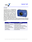
genesys ideation Finch Imager User’s Manual 6/9/2014 Finch Imager Contents 1 2 3 Introduction .......................................................................................................................................... 3 1.1 Overview ....................................................................................................................................... 3 1.2 Features ........................................................................................................................................ 3 Imager Card Details ............................................................................................................................... 3 2.1 Block Diagram ............................................................................................................................... 3 2.2 Finch Components ........................................................................................................................ 4 2.2.1 FPD-Link III SMB Interconnect............................................................................................... 4 2.2.2 Power Regulators .................................................................................................................. 4 2.2.3 Power Sequencer .................................................................................................................. 4 2.2.4 AR0132AT Image Sensor ....................................................................................................... 4 2.2.5 DS90UB913AQ-Q1 Serializer ................................................................................................. 4 Hardware Reference ............................................................................................................................. 5 3.1 PCB Assembly Drawing ................................................................................................................. 5 3.1.1 4 Finch Imager Assembly Drawing ........................................................................................... 5 Software Reference .............................................................................................................................. 6 4.1 Key Features.................................................................................................................................. 6 4.2 Stages of Operation ...................................................................................................................... 6 4.2.1 System Initialization .............................................................................................................. 6 4.2.2 Board Startup ........................................................................................................................ 6 4.2.3 Clock Switch Over.................................................................................................................. 6 4.2.4 Normal Operation ................................................................................................................. 6 4.3 SW Block Diagram ......................................................................................................................... 7 4.4 Software Development Guide....................................................................................................... 8 4.4.1 Finch Devices......................................................................................................................... 8 4.4.2 Programming Guide .............................................................................................................. 8 2 genesys ideation proprietary information Finch Imager Finch Imager User’s Manual 1 Introduction 1.1 Overview The Finch Imager is a CMOS Imager Board that uses the Aptina AR0132AT HD imager as the source of the video data and the Texas Instruments DS90UB913AQ-Q1 FPD-Link III serializer for pixel data transport. 1.2 Features The main features include a high-definition CMOS imager, high-speed serializer, and a positive locking interconnect. A detailed list of features is as follows: 2 Aptina AR0132AT HD imager o 1/3” optical format o 1.2 Megaixel CMOS imager o Automotive temp range and qualified part o 1280Hx960V max resolution o High-Dynamic Rrange or linear mode o Bayer pixel format o 60 frames per second max data rate Texas Instruments TBD FPD-Link III serializer o Power, pixel data and backchannel over 1 conductor o I2C backchannel interface for camera configurations o Automotive temp range and qualified part Interconnect o FAKRA coaxial interconnect using SMB connectors o Supports automotive voltage ranges (9V-16V) Imager Card Details 2.1 Block Diagram The following block diagram of the Finch Imager illustrates the various functions in the design: 3 genesys ideation proprietary information Finch Imager 2.2 Finch Components 2.2.1 FPD-Link III SMB Interconnect The SMB connector manages the connection to the Harrier daughter card. The connection allows the imager board to receive power from the Harrier daughter card, channels the imager pixel data, and has embedded I2C backchannel for inter-board communication, all on a single Coax cable. 2.2.2 Power Regulators There are several power supplies on the Finch board. The FAKRA connector provides a coaxial connection for power, pixel data, and I2C backchannel. The power input supplied to the Finch board can range between 9V and 16V. 2.2.3 Power Sequencer This circuit controls starting up the imager and SerDes in the correct order. 2.2.4 AR0132AT Image Sensor The Aptina AR0132AT image sensor is the main component on the board and captures images and outputs the pixel data on a parallel interface which is connected to the FPD-Link III serializer. The imager can be configured via an I2C interface. This configuration interface is multiplexed on the FPD-Link III back channel. The imager can capture video with a maximum resolution and throughput of up to 1280x960p at 45fps or 1280x720p at 60fps. 2.2.5 DS90UB913AQ-Q1 Serializer The Texas Instruments FPD-Link III serializer converts parallel image data to serial data and transports pixel data via a coaxial cable to the Harrier daughter card. The serializer also provides an I2C backchannel that can be used for I2C communication to other devices (such as the Aptina imager) as well as some GPIO. This GPIO can be used for triggering imager exposure. 4 genesys ideation proprietary information Finch Imager 3 Hardware Reference 3.1 PCB Assembly Drawing The following figures contain assembly drawings of the PCBs for the Finch Imager. 3.1.1 Finch Imager Assembly Drawing The following figure details the placement of components on the top of the Finch Imager board. The main components on the top side of the board are the imager (U2) and the serializer (U3). The following figure details the placement of components on the bottom of the Finch imager board. The main components on the bottom side of the board are passives for decoupling the imager and serializer and the SMB FAKRA connector (J1). 5 genesys ideation proprietary information Finch Imager 4 Software Reference 4.1 Key Features The imager and serializer are configured and controlled through an I2C interface. This interface is transported through a back channel (from the deserializer and to the serializer) and a forward channel (from the serializer and to the deserializer) over the coaxial cable via the FPD-Link III interface. The FPD-Link II interface also provides a method to manipulate GPIO. The GPIO on the Finch Imager Board can be used for exposure. 4.2 Stages of Operation As illustrated in the block diagram in paragraph 4.3, the operation of the Finch Imager Board goes through 4 stages of operation: System Initialization Board Startup Clock Switch Over Normal operation 4.2.1 System Initialization In order for the Finch Imager Board to operate, an I2C master is required on the other side of the FPDLink III interface. The demonstration software provided utilizes an open cores I2C interface and the Nios II soft processor. The Harrier Board also uses I2C IO expanders to manipulate LED indicators, clock switch over circuitry, and exposure. For more information on the Harrier Board operation, please refer to the Harrier Board User’s Manual. 4.2.2 Board Startup After the FPGA, processor, and Harrier Board are initialized, the serializer should achieve lock with the external 48 MHz clock. This will allow the processor in the system to initialize the imager and serializer (via the I2C interface) correctly for normal operation. The camera board will not transmit valid pixel data at this time since the clocks for the FPD-Link III interface and the pixel rate from the imager are not synchronized. This occurs in the next stage of operation. 4.2.3 Clock Switch Over Once the imager and serializer are initialized, the imager will be sending out the correct pixel clock needed for synchronized serializer communication. The processor will assert the clock switch over IO and change the clock source from external clock to pixel clock mode on the serializer. This will cause the link to lose lock, switch over to the new serdes bit rate and will regain lock after a small period of time. 4.2.4 Normal Operation After successfully switching the clock from external oscillator to pixel clock mode, the camera should begin transmitting valid pixel data. The demonstration software operates the board in 1280x720 resolution at 60 fps. 6 genesys ideation proprietary information Finch Imager 4.3 SW Block Diagram The block diagram of the demonstration software is as follows: Figure 4-1: High-Level Finch Software Algorithm 7 genesys ideation proprietary information Finch Imager 4.4 Software Development Guide The following section includes relevant information for software developers interested in writing custom drivers for the Finch camera boards. 4.4.1 Finch Devices Please note that all Finch Imagers use the same I2C address. Developers should make use of the I2C device aliasing present on the Harrier daughter card to address multiple imagers. 4.4.1.1 Aptina AR0132AT Image Sensor The Aptina AR0132AT image sensor I2C 8-bit write address is 0x20; the read address is 0x21. In order to communicate with a specific Finch image sensor developers should take advantage of the alias address mapping capabilities of the FPD-Link III deserializer (refer to the “Multiple Device Addressing” description in the DS90UB914/913Q datasheet). For a complete list of AR0132AT internal registers, please reference the AR0132AT register reference manual (which must be acquired directly from Aptina). 4.4.1.2 Texas Instruments DS90UB913Q FPD-Link III Serializer The Texas Instruments DS90UB913A-Q1 FPD-Link III serializer I2C 8-bit write address is 0xB0; the 7-bit read address is 0x58. In order to communicate with a specific Finch serializer, developers should take advantage of the alias address mapping capabilities of the FPD-Link III deserializer (refer to the “Multiple Device Addressing” description in the DS90UB913A-Q1 datasheet). For a complete list of DS90UB913AQ1 internal registers, please reference the DS90UB913A-Q1 register reference manual. 4.4.2 Programming Guide The Finch Imager utilizes three GPIO pins to control indicators and exposure. The GPIO pins are controlled through the I2C back channel. Please reference the “Harrier Daughter Card User Manual” for more information. 4.4.2.1 Exposure control The exposure control GPIO pin is used to control the camera trigger time from the Harrier daughter card. In order to use the exposure trigger, the status GPIO must first be asserted. 8 genesys ideation proprietary information