1
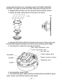
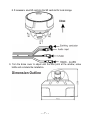
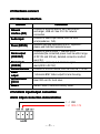
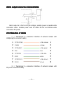
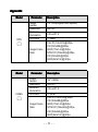
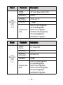
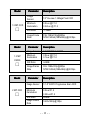
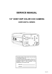
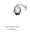
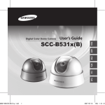
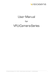
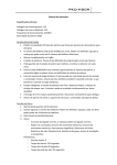
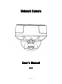
Network Camera
User
User’’s Manual
V1.
V1.331
--1--
--Content-...................................................... - 3 CHAPTER 1 PROFILE
PROFILE......................................................
1.1 FUNCTIONS AND CHARACTERISTICS.............................. - 3 1.2 APPLICATIONS.......................................................... - 4 .............................................
.............................................-- 4 CHAPTER 2 INSTALLATION
INSTALLATION.............................................
2.1 NOTICE................................................................... - 4 2.2 HANDLING OF THE UNIT.............................................. - 5 2.3 PARTS DESCRIPTION..................................................- 5 2.4 COVER REMOVAL AND ATTACHMENT............................. - 5 2.5 HARDWARE CONNECT................................................ - 8 2.5.1 Hardware interface...........................................- 8 2.5.2 Alarm input/output connection........................... - 8 2.5.3 Selection of reticle............................................- 9 ...................................
...................................-- 10 CHAPTER 3 PARAMETER SETUP
SETUP...................................
3.1 SETUP PARAMETER BY IE BROWSER........................... - 10 ..................................................................... - 11 APPENDIX
APPENDIX.....................................................................
This manual is suitable for IP DOME series
--2--
Chapter 1 Profile
Network Camera is a kind of embedded digital surveillance product
collected traditional simulation camera and network video server. Adopts
embedded Linux operation system and SOC hardware platform of Graim Corp.
And has characteristics of high efficiency on system adjustment, solidified code
on Flash, small bulk, high stability and reliability.
1.1 Functions and Characteristics
Basic Function
� Video compression tech: adopts H 264 video compression tech, high
compression ratio with super agility handling.
� Network function: integrate TCP/IP protocols and video, alarm, voice data
supported, built-in WEB browser, IE interview supported.
� Heartbeat function: host computer is able to know running state of network
camera real time by heartbeat function.
� PTZ control function: control for PTZ, kinds of decoder protocols and dome
cameras supported.
� Alarm function: signal parameter alarm input, on-off parameter alarm
output, motion detective, video lost, mask alarm, alarm link output.
� Voice speech: two-way voice speech, one-way voice broadcast.
� POE power supply supported.
� User management: multi-level user popedom management.
Compression Handling Function
� Separate hardware compression, adopts H.264 compression standard on
video compression, not only support change code ratio, but also support
change frame ratio, while setting up video image quality, it’s able to restrict
compression bit rate of video image.
� 1920*1080p, 1600*1200p, 1280*720p, D1(PAL:704*576, NTSC:704*480),
CIF(PAL:352*288, NTSC:352*240), QCIF(PAL:176*144, NTSC:240*160)
supported
� OSD supported, date and time setup available.
Remote interview and transmission function
� One self-compliant 10M/100M Ethernet interface as standard accessory..
� PPPoE, DHCP, DDNS protocol supported.
� Available to set parameter, browse real time video, check network camera
--3--
state through applications or IE browser. Available to realize alarm link and
save compressed bit rate through network.
� Available to realize remote upgrade and maintenance through network.
1.2 Applications
�
�
�
�
�
�
�
�
�
Suitable for circumstances required for network remote surveillance
ATM, Bank Counter, Supermarket, Factory etc
Nursing House, Kindergarten, School etc.
Intelligentized door management system
Intelligentized Building, intelligentized community management system
Electricity station, telecom base station etc unmanned on duty system
Outdoor bridge, tunnel, crossing traffic etc surveillance system
flowing line and warehouse surveillance
24h surveillance to road traffic
Remote surveillance to forest, fountain and river etc.
Chapter 2 Installation
2.1 Notice
1. Do not attempt to point the camera at the sun or other extremely bright
objects that cause smear to appear no matter the camera is power on or not. It
leads to damage of the CCD(Charge Coupled Device).
2. Make sure to use a ceiling board having enough strength to support this
camera.
3. Assemble the camera's main parts and lens quickly in a sanitary place.
4. Do not pull the cable, it may cause disconnection.
5. When camera is installed next to equipment such as wireless
communication device which emits a strong electromagnetic field some
irregularity such as noise on the monitor screen may happen.
6. Make sure to use proper screws which cameras can be bear on the
material firmly.
7. Do not touch the inside of camera even if something is wrong.
8. Makes sure to disconnect the power supply first before installation, check
the ground connection, and then install it.
--4--
2.2 Handling of the unit
1. Never attempt to disassemble or modify the camera.
2. If an abnormality should occur, immediately turn off the power and consult
your dealer.
2.3 Parts Description
2.4 Cover Removal and Attachment
To remove the body cover and camera body, disassemble it with the L
WRENCH provided in your ACCESSORY set. (Rotating clockwise will close it
and rotating anti-clockwise will release it.)
1. PLASTIC ANCHOR: insert into the SCREW hole of the installation
location (to strengthen the installation).
2. ASSY SCREW TAPPING: use for installation on the ceiling or wall.
3. OPENING TOOL: if needed open the pipe hole by opening tool.
4. L WRENCH for: body cover and camera base assembly.
5. TEMPLATE: guide for installation.
6. RUBBER PADS: tick rubber pad on the camera base for waterproof.
Installation Instruction
1. Attach the provided TEMPLATE to where you want to install the
--5--
camera,and then drill a hole. Completely insert the PLASTIC ANCHOR
provided. Then lead the power and video cables pass through the hole.
2. Disassemble the body cover and camera base from dome camera.
3. Fasten the dome camera base on the wall or the ceiling.
4. Adjusting the Camera Direction Camera body moves in three ways: pan,
tilt and rotate. Adjust the direction so that the lens is pointing at the target.
5. Use the lever to adjust the view angle and focus.
6. Connected the network cable.
7. Connected the power cable carefully and tightly (disconnected the power
cable, if power over Ethernet function was option).
--6--
8. If necessary, plug SD card into the SD card slot for local storage.
9. Turn the dome cover to adjust until the lens point at the window, screw
tightly and complete the installation.
--7--
2.5 Hardware connect
2.5.1 Hardware interface
Interface
Network
interface (NIC)
Audio input
Power (DC12V)
Alarm output
(COM OUT)
Alarm input
(COM IN)
RS-485 interface
Video
output
SD card insert
groove
RESET
Connection
Connect to Ethernet device, such as Ethernet
exchanger, HUB etc. See 2.5.3 for network
connection.
Connect to audio input device, such as tone
arm(impedance: 1kΩ) .
Detailed type see parameter form in “Appendix”,
please use matched manostat power.
Connect to alarm output, 1 channel on-off
parameter(the connected power must be within range
of DC12V and 300mA), detailed connection method
see 2.5.2
Connect to alarm input, 2 channels signal
alarm(DC5V~DC12V) .
Connect to RS-485 device, such as Pan/Tile, PTZ etc.
1 channels BNC Video output for lens focusing.
Insert SD card for local save.
RESET button, restore ex-factory value.
output connection
2.5.2 Alarm input/
input/output
tput connection demonstration
Alarm in
intput
( -) GND
(+)DC5-12V
--8--
Alarm output connection demonstration
Alarm output is in fact on-off (No voltage), outside power is needed while
connection alarm. Outside power must be within DC12V and 300mA while
connection DC power.
2.5.3 Selection of reticle
( 1 ) Twisted-pair to connection interface of network camera with
HUB(straight connection cable)
( 2 ) Twisted-pair to connection interface of network camera with
PC(cross connection cable)
--9--
Chapter 3 Parameter setup
Some network parameters must be setup firstly after finishing installation,
includes IP address, submask, port etc, can be setup through many kinds of
ways, see below two kinds for examples:
1. Setup parameters such as IP address and PPPoE etc through IE browser
2. Setup parameters through applications on client’s side.
Please be confirm PC and network camera already be connected, and the
network camera can be PING!
3.1 Setup parameter by IE browser
The default IP:192.168.0.120, default port:30001, superuser: admin,
superuser password: admin
Login network camera by IE, input IP address, and will shoot out logging in
window, input username and password, click “login” to enter IE client interface.
Function detailed guide please refer to “Network Video Manager System
Manual”.
Important Note: to check device by IE, the premise is to set browser security
level, open IE browser, enter “tool/Internet option/security/user-defined level”,
set security level ”security level-low”, or directly set “ActiveX, Widget and
Insert ”to open.
- - 10 - -
Appendix
Model
DPS
Parameter
Image
Sensor
Resolution
Minimum
illumination
S/N Ratio
□
Image Frame
Rate
Model
COMS
Parameter
Image
Sensor
Resolution
Minimum
illumination
S/N Ratio
□
Image Frame
Rate
Description
1/3" DPS(Digital Pixel System)
540TVL
0.5Lux/F1.2
≥48dB
PAL:D1(704x576)@25fps,
CIF(352x288)@25fps,
QCIF(176x144)@25fps,
NTSC:D1(704x480)@30fps,
CIF(352x240)@30fps,
QCIF(240x160)@30fps.
Description
1/4" CMOS
450TVL
0.3Lux/F1.2
≥45dB
PAL:D1(704x576)@25fps,
CIF(352x288)@25fps,
QCIF(176x144)@25fps;
NTSC:D1(704x480)@30fps,
CIF(352x240)@30fps,
QCIF(240x160)@30fps.
- - 11 - -
Model
Parameter
Image
Sensor
Resolution
High
Resolution
CCD
Minimum
illumination
S/N Ratio
□
Image Frame
Rate
Model
Low
Resolution
CCD
Parameter
Description
1/3" Sony Super HAD II CCD
540TVL
0.008Lux/F1.2
≥48dB
PAL:D1(704x576)@25fps,
CIF(352x288)@25fps,
QCIF(176x144)@25fps;
NTSC:D1(704x480)@30fps,
CIF(352x240)@30fps,
QCIF(240x160)@30fps.
Description
Image
Sensor
1/3” Sony CCD
Resolution
500TVL
Minimum
illumination
0.03Lux/F1.2
S/N Ratio
≥50dB
Image Frame
Rate
PAL:D1(704x576)@25fps,
CIF(352x288)@25fps,
QCIF(176x144)@25fps;
NTSC:D1(704x480)@30fps,
CIF(352x240)@30fps,
QCIF(240x160)@30fps.
□
- - 12 - -
Model
1.3 MP CCD
□
Model
1.3 MP
CMOS
□
Model
2 MP CCD
□
Parameter
Description
Image
Sensor
1/3" Ex-view 1.3Mega Pixel CCD
Minimum
illumination
0.5Lux @ F1.2
0.02Lux @ F1.2
S/N Ratio
≥48dB
Image Frame
Rate
PAL:1280x720p@25fps
NTSC:SXGA(1280x960p)@22.5fps
Parameter
Description
Image Sensor
1/3” MT9M033 COMS
Minimum
illumination
0.5Lux @ F1.2
0.1Lux @ F1.2
S/N Ratio
≥48dB
Image Frame
Rate
PAL:1280x720p@25fps
NTSC:SXGA(1280x960p)@22.5fps
Parameter
Description
Image Sensor
1/1.8" SONY Progressive Scan CCD
Minimum
illumination
0.5Lux/F1.2
S/N Ratio
Image Frame
Rate
≥48dB
0.02Lux/F1.2
1600x1200p@15fps
- - 13 - -
Model
2 MP CMOS
□
Parameter
Description
Image Sensor
1/2.5” MT9P031 CMOS
Minimum
illumination
0.5Lux/F1.2
S/N Ratio
≥48dB
PAL:1920x1080p@25fps
NTSC:1920x1080p@30fps
0.1Lux/F1.2
Image Frame
Rate
Parameter
Description
Video out
1 BNC(PAL/NTSC, 1.0Vp-p,75Ω)
Video
Compression
H.264(ISO/IEC 14496-10)/MJPEG
Bit stream
Control
CBR、VBR
Audio
Input/Output
1 internal Microphone In, 1 External Microphone In,
1 Audio Line Out
Audio
Compression
G711/8KHz,16bits
G723.1/6.3kbps (Options)
AMR (Options)
Audio bit stream
6.3Kbps
OSD
Time/date/channel NO./
channel name/user-defined
Audio and video
sync
Motion
detection
Support
Support
- - 14 - -
Heartbeat
Two-way voice
talkback
Support
Support
Alarm and
event handling
Through built-in dynamic detection or external input or
planned to trigger the events; Through FTP, Email and
HTTP uploading images and issued a notice
Network
transmission
control
Embedded network bandwidth adaptive flow control
technology
Web Server
Microsoft Internet Explorer Version 5.5 or higher
Network
Protocol
IPv4/v6、RTP/RTCP、TCP/UDP、HTTP、DHCP、
DNS、FTP、DDNS、PPPOE、SMTP
Network
Ethernet
RJ-45,10/100Base-T
Alarm
Input/Output
1 Alarm Input,1 Alarm Output
RS485
1 Output (1 Input Options)
SD Card
Support MicroSD/HC, MiniSD/HC
Safely
Watchdog, Password protection
Temperature
(℃)
Supplied
Voltage
-10-60℃, RH10-90% (RUN)
-20-70℃, RH0-95% (STORE)
POE
802.3af POE(Power over Ethernet)
CMS Client and
SDK
Open API for application integration including SDK
9~12VDC ±5%,1000mA
- - 15 - -