1
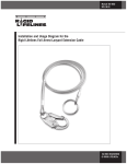
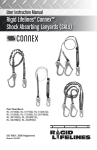
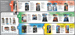
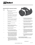
User Instruction Manual
ANCHOR TROLLEY
ISO 9001: 2008 Registered
Manual 103-0054
™
Read and understand this user instruction manual before using
this equipment.
It is the responsibility of the user and the user’s management
to be certain the user is thoroughly trained in and complies with
the proper installation, operation, and limitations.
When used as instructed, the Rigid Lifelines® Anchor Trolley™ can
reduce the user’s risk of injury from potentially hazardous falls.
Misuse of the trolley can result in serious or fatal injury.
The Anchor Trolley™ is part of a larger fall protection system. Prior
to use, the user must thoroughly read and understand the user
instruction manuals that came with the rigid track system, fall
arrest safety harnesses, and related equipment.
All fall protection programs are required to include a rescue plan.
As described in the inspection checklists in this user instruction
manual, inspect this equipment before each use, after every fall
event, and annually.
If the trolley does not roll smoothly because the brakes are
engaged, the trolley must be inspected. Remove the trolley from
service immediately, even if you do not see the fault indicator.
The swiveling connector, center shaft, and hardened teeth set
screws can ONLY be adjusted, serviced, repaired, or replaced
by Rigid Lifelines. Do NOT attempt any service to the swiveling
connector, center shaft, and hardened teeth set screws.
User attempts at re-adjusting the hardened teeth set screws
may cause the trolley to either “drag” or not stop properly during
a fall event.
For shortest fall distance, use a self-retracting lanyard with the
Anchor Trolley.™
DO NOT EXCEED 30° OFF-PLUMB (OFF-CENTER) LOADING.
Keep this instruction manual for future reference and new users.
Rigid Lifelines® Anchor Trolley™ Manual
800-869-2080
2
Stop the Drift,
Start the Self-Rescue!
The Rigid Lifelines® Anchor Trolley™ is the connection between
the user’s lanyard and the rigid track fall protection system.
The Anchor Trolley™ follows the user along the full length of
the track. User benefits from this unique trolley include:
■
■
■
A
uto-braking that greatly increases the opportunity
for self-rescue
A
n exclusive, patent-pending anchor design featuring
hardened teeth set screws to immediately engage the rigid track,
virtually eliminating post-fall drift without damaging the track
A
swiveling connector that rotates 360°…and swivels off-plumb
(off-center) to eliminate side-loading stresses. Note: Do not exceed
30° off-plumb (off-center) loading.
■
W
eatherproof, temperature-proof, lubrication-free operation
■
W
ear resistant, long-lasting construction
■
C
ompatibility with most rigid track
■
C
ompatibility with enclosed rigid track that has
Mylar™ Lip Seals
The Anchor Trolley is now standard equipment on all
engineered track fall protection systems from Rigid Lifelines —
and it can be retrofitted onto all of our earlier systems.
3
Rigid Lifelines® Anchor Trolley™ Manual
800-869-2080
Anchor Trolley Components
& Spare Parts Kits
™
1
3
2
4
5
10
6
9
7
8
Item
Description
Part Number
Qty.
1
DUST CAP
8-0341
1
2
500 AXLE SPACER
9A1052-1
4
3
500 SERIES AXLE
9A1051
2
4
WHEEL, 500, POLY
9-1662-5
4
5
SNAP RING
20-0016
4
6
GUIDE ROLLER
26-0028
2
7
SHOULDER BOLT (STAINLESS STEEL)
101-0219-SS
2
8
SWIVELING CONNECTOR
30-0006
1*
9
CENTER SHAFT
N/A
1*
10
HARDENED TEETH SET SCREWS
N/A
8*
*Factory Service Only
Spare Parts Kits
Guide Roller Spare Parts Kit: includes two shoulder
bolts and two guide rollers.
Part No. K-ATR-GR
Wheel Spare Parts Kit: includes four wheels, four
spacers, four snap rings, and two axles.
Part No. K-ATR-W
Call Rigid Lifelines at 800-869-2080 to order these Spare Parts Kits.
Rigid Lifelines® Anchor Trolley™ Manual
800-869-2080
4
Installation (including Retrofit)
The Anchor Trolley™ is ready to install right out of the box:
1) Unbolt an end stop on your overhead rigid track.
2) Remove the existing trolley.
3) Install new Anchor Trolley.™
4) Reinstall the track’s end stop.
Inspect Before Each Use
1) T est the operation of the trolley’s swiveling connector and verify
that the connector can rotate and swivel freely.
2) V
erify that the trolley can easily traverse the entire length of
track and that its wheels rotate freely.
In the unlikely event that the trolley does NOT move easily,
this could indicate that there is a problem with the anchor’s
spring mechanism. Inspect the center shaft immediately above
the swiveling connector: the center shaft is engineered to
produce a fault-indicating groove if there is a spring failure.
If any of these faults occur:
1) The swiveling connector does not rotate
or swivel freely, or
2) The trolley wheels are not moving freely,
remove the trolley from service
and call Rigid Lifelines at
800-869-2080 for instructions.
Fault Indicator:
a groove appears if
there is a spring failure.
General Maintenance
1) C
heck the torque on the bolt that fastens the swiveling
connector. Torque must be 25 ft-lbs using a 3/8" hex-key socket.
Never loosen or remove this bolt.
2) T he Anchor Trolley™ wheels have sealed bearings and therefore
require no lubrication.
3) T he hardened teeth set screws are factory-set. Do not attempt to
re-adjust the set screws; doing so may cause the trolley to either
“drag” or not stop properly during a fall event.
5
Rigid Lifelines® Anchor Trolley™ Manual
800-869-2080
Track Splice Adjustments
If the trolley is not moving freely (e.g., “hanging up”) and/or you
hear or feel it scraping against the sides of the track, the track’s splices
may be too tight. Re-adjust the splices’ side bolts so the track is not
“pinched” and the trolley moves freely the entire length of the track.
Guide Roller Maintenance & Replacement
If the trolley wheels are moving smoothly but you hear and/or
feel metal scraping against the track, check the guide rollers:
1) Remove an end stop of the enclosed track to roll out the trolley.
2) Inspect the two guide rollers: if they are cracked, abraded, or
missing, they must be replaced. (See page 4 for Guide Roller
Spare Parts Kit.)
Replace the guide rollers using a Guide Roller Spare Parts Kit as follows:
3) Use a 1/8" hex-key (Allen®) wrench to loosen the shoulder bolt
4) Remove shoulder bolt and guide roller.
5) Install the new guide roller and then the shoulder bolt.
6) Use a 1/8" hex-key (Allen®) wrench to tighten the shoulder bolt.
7) Torque shoulder bolt to 10 ft-lbs.
Wheel Maintenance & Replacement
If the trolley is not gliding smoothly and/or you hear metal scraping
(and you have already checked both the track splices and the guide
rollers as instructed above), inspect the trolley wheels:
1) Remove an end stop of the enclosed track to roll out the trolley.
2) Inspect the four trolley wheels. If they are cracked, abraded,
or otherwise worn so they cannot roll smoothly, they must be
replaced. (See page 4 for the Wheel Spare Parts Kit.)
Replace the trolley wheels using a Wheel Spare Parts Kit as follows:
3) W
ARNING: USE PROTECTIVE EYEWEAR. Using a pair of pliers,
remove the snap rings.
4) Pull the worn wheels and their spacers off of their axle.
5) P ull out and check the axles; if they have been bent or otherwise
damaged, replace them with new axles.
6) Install the new spacers onto the axles.
7) Install the new wheels and their new snap rings.
8) By hand, spin each wheel to ensure that it moves freely.
Rigid Lifelines® Anchor Trolley™ Manual
800-869-2080
6
Rigid Lifelines Anchor Trolley
Inspection Checklists
®
™
Download and print additional blank checklists from the literature
section at rigidlifelines.com
Inspector Name:
Date:
Inspection Points: Before Each Use Pass
Fail
Pass
Fail
Test the operation of the trolley’s swiveling connector to
verify that it rotates and swivels freely.
Verify that the trolley can easily and smoothly roll the
full length of track.
Inspection Points: Annually and After Every Fall Event
Remove the Anchor Trolley™ for a thorough inspection. In
particular, inspect the swiveling connector, shaft, and body
of the trolley for any signs of damage, bending, misalignment,
broken welds, cracks, corrosion or excessive wear that would
obviously interfere with the normal performance of the trolley.
Check the torque on the bolt that connects the swiveling
connector. Torque must be 25 ft-lbs using a 3/8" hex-key
socket. Never loosen or remove this bolt.
Inspect the hardened teeth set screws to assure that the fall
did not cause obvious damage to the teeth.
After repeated fall events, an Anchor Trolley™ may eventually
experience some wear on its hardened teeth set screws. Such
wear could conceivably reduce its braking performance,
causing the trolley to “skip” slightly.
To confirm that there has been no reduction in braking
performance, tie a regular piece of rope (NOT your fall
arrest lanyard) around the swiveling connector and then
pull down hard (at least a 50 pound load) on the rope and
attempt to move the trolley. If the trolley moves at all or
skips slightly while braking under a continuous 50+ lb. load,
remove the trolley from service and call Rigid Lifelines®
at 800-869-2080.
If the Anchor Trolley™ fails ANY of the above inspection points, immediately
remove the trolley from service and call Rigid Lifelines at 800-869-2080
for instructions.
WARNING: The hardened teeth set screws are NOT user-serviceable.
Do NOT attempt to re-sharpen worn teeth or re-adjust their set-screws.
Hardened teeth set screws can ONLY be replaced at the Rigid Lifelines
factory by our trained technicians.
7
Rigid Lifelines® Anchor Trolley™ Manual
800-869-2080
Anchor Trolley Warranty Statement
™
The Anchor Trolley™ is covered under a 5-year warranty. Rigid Lifelines
warrants the equipment and wearable end truck and trolley wheels only to
be free from defects in material and workmanship for a period of five (5) years
or 10,000 hours (whichever occurs first), commencing on the date of shipment
to the first retail purchaser (“Purchaser”).
Rigid Lifelines is dedicated to offering superior service and quality products
to all of our customers. If you would like to contact a customer service
representative, please call the following number: 1 (800) 869-2080. We will
be happy to assist you in any way that we can.
These warranties do not extend to equipment which has been subject to
misuse, use in excess of rated capacity, negligent operation, use beyond Rigid
Lifelines published service factors, improper installation or maintenance, and
does not apply to any equipment which has been repaired or altered without
Rigid Lifelines written authorization.
Written notice of any claimed defect must be given to Rigid Lifelines within
thirty (30) days after such defect is discovered. Rigid Lifelines obligation, and
Purchaser’s sole remedy under this warranty is limited to, at Rigid Lifelines
discretion, the replacement or repair of the equipment at Rigid Lifelines factory
or at a location approved by Rigid Lifelines. Purchaser is responsible for all freight
and transportation costs relating to the repair or replacement of the equipment.
THIS WARRANTY IS EXPRESSLY IN LIEU OF ALL OTHER WARRANTIES WHATSOEVER
WHETHER EXPRESS, IMPLIED, OR STATUTORY. SELLER MAKES NO WARRANTY
AS TO THE MERCHANTABILITY OR FITNESS FOR A PARTICULAR PURPOSE OF THE
EQUIPMENT AND MAKES NO OTHER WARRANTY, EITHER EXPRESS OR IMPLIED.
Rigid Lifelines shall not be liable, under any circumstances, for any indirect,
special, or consequential damages including (but not limited to): lost profits,
increased operating costs, or loss of production. This warranty shall not extend
to damages including (but not limited to): lost profits, increased operating
costs, or loss of production. This warranty shall not extend to any components
or accessories not manufactured by Rigid Lifelines (example: casters), other than
the components and systems manufactured by XSPlatforms, and purchaser’s
remedy for such components and accessories shall be determined by the
terms and conditions of any warranty provided by the manufacturer of such
components and accessories.
Rigid Lifelines
604 Hemlock Road
Morgantown, PA 19543
Toll Free: (800) 869-2080
Local: (610) 286-7200
Fax: (610) 286-0085
rigidlifelines.com
[email protected]
©2013. All rights reserved. Specifications subject to change without prior notice. RLL-ATUIM0713V1