1
The slow (speed) control loop is executed with a period of one millisecond, and is performed in
the Startup, Spin, and Freewheel sub states of the Run state. It is calculated immediately after
the fast (current) control loop, and the exact instance of its execution is determined by the countdown software timer gsM1_Drive.uw16CounterSlowLoop, which is updated after each pass
of the fast (current) control loop. The calculation comprises the ramp limitation of the required
speed (which determines the acceleration of the drive) and the PI speed controller, whose output
gives the required iq current which enters the vector control algorithm, and is directly proportional
to output torque of the motor.
4.6.5 Scalar control
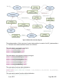
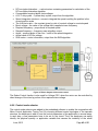
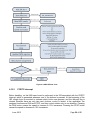
In order to evaluate the proper setting of the Back-EMF observer and tracking observer
parameters, and the values and shapes of the sensed currents, there is scalar control (Volt-perHertz) of the PMS motor incorporated into the control structure. It is recommended to run the
application in this mode only while the application is mastered by the MCAT tool, because this
tool automatically calculates the Voltage/Frequency ratio based on the motor parameters. The
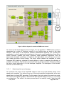
block diagram of the scalar control is shown on Figure 4-7.
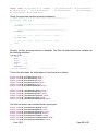
The structure listed below serves for the scalar control:
typedef struct
{
sFrequencyRampParams;
/* Parameters of frequency ramp */
GFLIB_RAMP_T
sUDQReq; /* Required voltage vector in d,q coordinates
MCLIB_2_COOR_SYST_D_Q_T
MCLIB_2_COOR_SYST_ALPHA_BETA_T
sUAlBeReq;/* Required Alpha/Beta voltage */
MCLIB_ANGLE_T
sAnglePosEl; /* Sine and Cosine values of the rotor angle for
Park transformation */
GMCLIB_ELIM_DC_BUS_RIP_T
sElimDCBRip; /* DCB ripple elimination parameters
structure */
/* Compensated to DC bus
MCLIB_2_COOR_SYST_ALPHA_BETA_T sUAlBeDCBComp;
Alpha/Beta voltage */
MCLIB_3_COOR_SYST_T
sDutyABC; /* Applied duty cycles ABC */
GFLIB_INTEGRATOR_TR_T sSpeedIntegrator; /* structure contains the integrator
parameters (integrates the angular speed
in order to get the position */
Frac32 f32VoltHertzRatio; /* constant defining the applied voltage level based on
actual frequency */
Frac32 f32BoostVoltage;
/* boost start-up voltage */
Frac32 f32SpeedCmd;
/* required electrical frequency from master system
Frac32 f32FrequencyRamp; /* Required frequency limited by ramp - the ramp output
Frac32 f32Angle;
/* Electrical angle of the rotor */
Frac32 f32UDcBusFOC;
/* DC bus voltage, scaled to phase voltage */
/* SVM sector */
UWord16 uw16SectorSVM;
}MCSTRUCT_SCALAR_CTRL_PMSM_T;
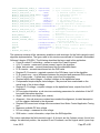
The description of the variables contained in the structure follows:
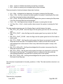
• Frequency ramp structure – serves to generate the frequency ramp
• Required D, Q voltage – the D voltage is kept to zero level (motor has permanent
magnets), the Q voltage is output from the Volt-per-Hertz equation
• Required alpha, beta voltage – the required voltage vector in alpha-beta coordinates
• Angle – electrical rotor angle (sine, cosine)
June, 2013
Page 42 of 55