1
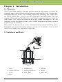
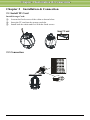
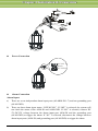
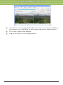
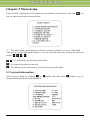
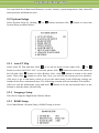
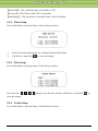
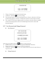
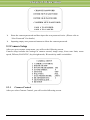
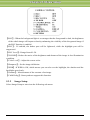
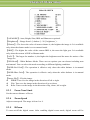
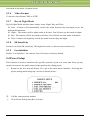
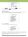
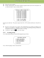
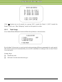
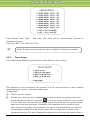
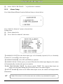
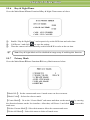
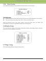
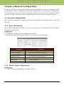
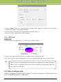
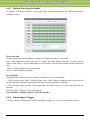
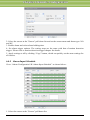
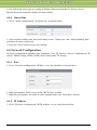
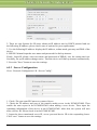
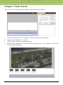
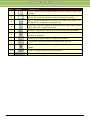
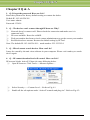
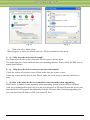
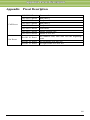
IP Speed Dome Camera User Manual Please read this instruction carefully for correct use of the product and preserve it for reference purposes Disclaimer This manual is provided for user reference only, without legal restraint. This content of this manual is subject to change without prior notice, and the updates will be added into the new version of this manual. This manual may contain several technically incorrect places or printing errors, please feel free to let us know. We will readily improve or update the precuts or procedures described in the manual. Notes on Safety Please use the specified power supply to connect (supports AC 24V). Do not attempt to disassemble the camera; in order to prevent electric shock, do not remove screws or covers. There are no user-serviceable parts inside. Please contact the nearest service center as soon as possible if there is any failure. Avoid from in correct operation, shock vibration, heavy pressing which can cause damage to product. Do not use corrosive detergent to clean main body of the camera. If necessary, please use soft dry cloth to wipe dirt; for hard contamination, use neutral detergent. Any cleanser for high grade furniture is applicable. Avoid aiming the camera directly towards extremely bright objects, such as, sun, as this may damage the image sensor. Please follow the instructions to install the camera. Do not reverse the camera, or the reversing image will be received. Do not operate it incase temperature, humidity and power supply are beyond the limited stipulations. Keep away from heat sources such as radiators, heat registers, stove., etc. Do not expose the product to the direct airflow from an air conditioner. Otherwise, it may cause moisture condensation inside the clear dome due to temperature difference between internal and external of the dome camera. Contents Chapter 1 Introduction....................................................................................... 1 1.1 Overview .............................................................................................. 1 1.2 Interfaces and Parts .............................................................................. 1 Chapter 2 Installation & Connection ................................................................. 2 2.1 Install TF Card ........................................................................................ 2 2.2 Connection.............................................................................................. 2 2.3 Install CMS/NVMS ................................................................................ 4 Chapter 3 IE Remote Access ............................................................................. 5 3.1 LAN ..................................................................................................... 5 3.1.1 Access through IP-Tool ............................................................. 5 3.1.2 Directly Access through IE ........................................................ 6 3.2 WAN..................................................................................................... 7 Chapter 4 Remote Preview ................................................................................ 9 4.1 Remote Preview ..................................................................................... 9 4.2 Playback ............................................................................................... 10 4.3 Snap ...................................................................................................... 11 Chapter 5 Menu Setup ........................................................................................ 13 5.1 System Information ............................................................................ 13 5.2 System Setup ...................................................................................... 14 5.2.1 Auto PT Flip ............................................................................ 14 5.2.2 Language Setup ....................................................................... 14 5.2.3 RS485 Setup ............................................................................ 14 5.2.4 Time Setup............................................................................... 15 5.2.5 Title Setup................................................................................ 15 5.2.6 North Setup.............................................................................. 15 5.2.7 New Password and Change Password ..................................... 16 5.3 Camera Setup ..................................................................................... 17 5.3.1 Camera Control ....................................................................... 17 5.3.2 Image Setup ............................................................................. 18 5.3.3 Focus Near Limit ..................................................................... 19 5.3.4 Zoom Speed ............................................................................. 19 5.3.5 DZoom..................................................................................... 19 5.3.6 Video Format ........................................................................... 20 5.3.7 Day & Night Mode .................................................................. 20 5.3.8 IR Sensitivity ........................................................................... 20 5.3.9 Len Initialize ............................................................................ 20 5.4 Preset Setup ........................................................................................ 20 5.5 Dome Function ................................................................................... 21 5.5.1 Patrol Setup ............................................................................. 21 5.5.2 Grouping Setup........................................................................ 22 5.5.3 Task Setup ............................................................................... 23 5.5.4 Trace Setup .............................................................................. 24 5.5.5 Alarm Setup ............................................................................. 25 5.5.6 Day & Night Timer .................................................................. 26 5.5.7 Privacy Mask ........................................................................... 26 5.5.8 Home Position ......................................................................... 27 5.6 Display Setup ..................................................................................... 27 5.7 Wiper Setup ........................................................................................ 27 5.8 Load Default....................................................................................... 28 Chapter 6 Remote Configuration........................................................................ 29 6.1 System Configuration......................................................................... 29 6.1.1 Basic Information .................................................................... 29 6.1.2 Date & Time Configuration..................................................... 29 6.1.3 SD Card ................................................................................... 30 6.2 Video Configuration ........................................................................... 30 6.2.1 Camera Configuration ............................................................. 31 6.2.2 Video Stream ........................................................................... 31 6.2.3 OSD Configuration.................................................................. 31 6.2.4 ROI Configuration ................................................................... 32 6.3 PTZ Configuration ............................................................................. 33 6.3.1 Cruise Configuration ............................................................... 33 6.3.2 Upgrade PTZ ........................................................................... 34 6.4 Alarm Configuration .......................................................................... 34 6.4.1 Motion Detection Area ............................................................ 34 6.4.2 Motion Detection Trigger ........................................................ 35 6.4.3 Motion Detection Schedule ..................................................... 36 6.4.4 Alarm Input Trigger ................................................................ 36 6.4.5 Alarm Input Schedule .............................................................. 37 6.4.6 Alarm Out ................................................................................ 38 6.5 Network Configuration ...................................................................... 38 6.5.1 Port .......................................................................................... 38 6.5.2 IP Address ............................................................................... 38 6.5.3 Server Configuration ............................................................... 39 6.5.4 IP Notify .................................................................................. 40 6.5.5 DDNS Configuration ............................................................... 40 6.5.6 RTSP ....................................................................................... 41 6.5.7 UPNP ....................................................................................... 42 6.5.8 Mail Setting ............................................................................. 42 6.5.9 FTP .......................................................................................... 43 6.6 Advanced Configuration .................................................................... 44 6.6.1 User Configuration .................................................................. 44 6.6.2 Security Configuration ............................................................ 45 6.6.3 Configure Backup & Restore .................................................. 46 6.6.4 Reboot Device ......................................................................... 47 6.6.5 Upgrade ................................................................................... 47 Chapter 7 Video Search ...................................................................................... 48 Chapter 8 Q & A................................................................................................. 50 Chapter 9 Specifications ..................................................................................... 52 Appendix Preset Description ........................................................................... 53 C Chhaapptteerr 11 IInnttrroodduuccttiioonn Chapter 1 Introduction 1.1 Overview This IP speed dome camera is front-end equipment used for video capture. Its digital flip technology makes omni-directional and non-blind-spot monitoring into reality. It utilizes most advanced technologies, such as video encoding and decoding technology, and complies with the TCP/IP protocol, SoC., etc, to ensure this system more stable and reliable. This unit consists of two parts: the IP-CAM device and central management software (short for CMS/NVMS). This CMS/NVMS centralizes all devices together via internet or LAN and establishes a sound surveillance system to realize unified management and remote operation to all devices in one network. This product is widely used in banks, telecommunication systems, electricity power departments, law systems, factories, storehouses, uptowns, etc. In addition, it is also an ideal choice for surveillance sites with middle or high risks. 1.2 Interfaces and Parts 1 2 3 4 5 6 7 8 9 10 1 LAN 2 HP Audio Out 3 MIC In 4 CVBS Video Out 5 Alarm In/Alarm Out 6 RS485 7 Power 8 Safety Wire 9 Base Tray 10 Wiper IP-CAMERA User Manual - 1 C Chhaapptteerr 22 IInnssttaallllaattiioonn & &C Coonnnneeccttiioonn Chapter 2 Installation & Connection 2.1 Install TF Card Install Storage Card: ① Loosen the fixed screws of the cabin as shown below. ② Insert the TF card into the storage card slot. ③ Install back the cabin and fix it with the fixed screws. 2.2 Connection IP-CAMERA User Manual - 2 C Chhaapptteerr 22 IInnssttaallllaattiioonn & &C Coonnnneeccttiioonn N et Network Cable w or Router kC ab le Internet Network Cable Network Cable Ne Ca ble two rk Computer Sensor / Alarm Power Connection AC24V A Earth AC24V B Alarm Connection Alarm Input: a) There are seven independent alarm input ports (ALARM-IN1~7) and one grounding port (ALM-GND). b) There are three alarm input status: ―OFF/NC/NO‖. If ―OFF‖ is selected, the system will not check the status of the ALM-IN and ALM-GND. If ―NO‖ is selected, connect DC 5V~DC12V voltage between the alarm input port ALM-IN and the grounding port (ALM-GND) to trigger the alarm. If ―NC‖ is selected, disconnect the voltage between alarm input ports (ALM-IN) and grounding port (ALM-GND) to trigger the alarm. IP-CAMERA User Manual - 3 C Chhaapptteerr 22 IInnssttaallllaattiioonn & &C Coonnnneeccttiioonn Alarm Output: a) Supports 1 CH alarm output including OPEN and COM connections. b) Options: OFF, IN1. If the OFF is selected, no alarm can be output. If IN1 are selected, the alarm can be output only when the corresponding alarm input triggers the alarm. c) One passive switch for user to connect alarm devices. RS485 Connection You can connect keyboard to control the speed dome through the RS485 interface. 2.3 Install CMS/NVMS Find CMS/NVMS software from CD and then double click ―Setup.exe‖ file to pop up installation wizard. Install the software according to the prompts in the wizard. After you complete the installation, you will see the CMS/NVMS and IP-Tool icon on the desktop. Please see the user manual of this software for more details. If you need to install IP-Tool separately, please double click IP-Tool installation package and install it according its wizard prompts. After you finish installing, double click IP-Tool icon to start IP-Tool. IP-CAMERA User Manual - 4 C Chhaapptteerr 33 IIE ER Reem moottee A Acccceessss Chapter 3 IE Remote Access You may connect IP-Cam via LAN or WAN. Here only take IE browser (6.0) for example. The details are as follows: 3.1 LAN In LAN, there are two ways to access IP-Cam: 1. access through IP-Tool; 2. directly access through IE browser. 3.1.1 ① Access through IP-Tool Make sure the PC and IP-Cam are connected to the LAN and the IP-Tool is installed in the PC from the CD. ② Double click the IP-Tool icon on the desktop to run this software as shown below: ③ Modify the IP address. The default IP address of this camera is 192.168.226.201. Click the information of the camera listed in the above table to show the network information on the right hand. Modify the IP address and gateway of the camera and make sure its network address is in the same local network segment as the computer’s. Please modify the IP address of your device according to the practical situation. IP-CAMERA User Manual - 5 C Chhaapptteerr 33 IIE ER Reem moottee A Acccceessss For example, the IP address of your computer is 192.168.13.4. So the IP address of the camera shall be changed to 192.168.13.X. After modification, please input the password of the administrator and click ―Modify‖ button to modify the setting. ④ The default password of the administrator is ―123456‖. Double click the IP address and then the system will pop up the IE browser to connect IP-CAM. IE browser will auto download the Active X control. After downloading, a login window will pop up as shown below. Input the username and password to log in. The default username is ―admin‖; the default password is ―123456‖. 3.1.2 Directly Access through IE The default network settings are as shown below: IP address: 192.168.226.201 Subnet Mask: 255.255.255.0 Gateway: 192.168.226.1 HTTP: 80 Data port: 9008 You may use the above default settings when you log in the camera for the first time. ① Manually set the IP address of the PC and the network segment should be as the same as the default settings of the IP camera. Open the network and share center. Click ―Local Area Connection‖ to pop up the following window. IP-CAMERA User Manual - 6 C Chhaapptteerr 33 IIE ER Reem moottee A Acccceessss Select ―Property‖ and then select internet protocol according to the actual situation (for example: IPV4). Next, click ―Property‖ button to set the network of the PC. ② Open the IE browser and input the default address of IP-CAM and confirm. The IE browser will download Active X control automatically. ③ After downloading Active X control, the login dialog box will pop up. ④ Input the default username and password and then enter to view. 3.2 WAN Take access the camera by the router or virtual server for example: ① Make sure the camera is well connected via LAN and then log in the camera via LAN IP-CAMERA User Manual - 7 C Chhaapptteerr 33 IIE ER Reem moottee A Acccceessss and go to the ConfigNetwork ConfigPort menu to set up the port number. ② Go to Config Network ConfigIP Address menu to modify the IP address. ③ Go to the router’s management interface through IE browser to forward the IP address and port of the camera in the ―Virtual Server‖. Port Setup IP Setup Router Setup ④ Open the IE browser and input its WAN IP and http port to access. IP-CAMERA User Manual - 8 C Chhaapptteerr 44 R Reem moottee PPrreevviieew w Chapter 4 Remote Preview 4.1 Remote Preview After you log in, you will see the following window. The descriptions of the icon on the remote preview interface: Icon Description Motion alarm indicator icon Fix size Icon Description Sensor alarm indicator icon Start/Stop record Actual size Zoom in Playback Snap Zoom out Talk Full screen Open/close audio Move the cursor to view the live image in all directions after you click this button. Additionally, hold and drag the left mouse button to zoom in the live image. Right click mouse to appear a pull-down list: Stream: Four streams are optional. Turn off the live: Click this item to close the current live preview. Enable audio: Enable remote audio transmission. IP-CAMERA User Manual - 9 C Chhaapptteerr 44 R Reem moottee PPrreevviieew w Full screen: To open full screen display. Double click or click right mouse to return to the previous interface. Online user: To display the number of the online users accessing the device. System information: Display the device information. Click PTZ extended button to unfold PTZ control panel. In remote preview interface, you can view the image from every direction by controlling PTZ panel. The descriptions of the control panel are as follows: Button Description to rotate the dome upwards ; to rotate the dome downwards; to rotate the dome towards left; to rotate the dome towards right; to rotate the dome diagonally up-left;; to rotate the dome diagonally up-right; to rotate the dome diagonally down-left; to rotate the dome diagonally down-right; to stop rotating the dome. Drag the scroll bar to adjust rotating speed of the dome. Focus button. Click button to have long focus and click to have short focus so that you can adjust the image clearly. Zoom button. Click out the image. to zoom in the image; click to zoom Iris button. Click to increase light of the dome; click decrease light of the dome. Select preset and click to go to the preset; select cruise and click Select and set the preset and then click to to start cruise. to save the position of the preset. 4.2 Playback Click icon to see the following window: After selecting the record date, the record files will be displayed in the record file list box. Double click a certain record file to playback or check a certain file. Then click Play button to play. IP-CAMERA User Manual - 10 C Chhaapptteerr 44 R Reem moottee PPrreevviieew w 4.3 Snap Select the picture number and then click ―Snap‖ icon as shown below: To capture multiple pictures: ① Select the picture number from frame pull down list box, such as 2. ② Check ―Title‖ and ―Time‖ to show capture title and time on the captured pictures simultaneously. IP-CAMERA User Manual - 11 C Chhaapptteerr 44 R Reem moottee PPrreevviieew w ③ ④ ⑤ Click ―Browse‖ to set saving path and then click ―Save‖ to save pictures to HDD on the computer; Click ―Print Setup‖ to add the printer and print the snapped pictures. Click ―Snap‖ button to take snapshots. Drag the scroll bar to view all snapped pictures. IP-CAMERA User Manual - 12 C Chhaapptteerr 55 M Meennuu SSeettuupp Chapter 5 Menu Setup Under the PTZ control panel of IE remote preview interface, call Preset 95 and click can see main menu setup as shown below. you The menu setup can be displayed when the resolution of the live is set to 1920*1080. After you go to the main menu interface, you can select the menu by clicking the direction button ( ). :To select menu by moving up and down. :To return to the menu on the left. :To confirm to enter sub-menu or to select the menu on the right. 5.1 System Information Select System Setup by clicking or System Information menu as shown below: button and then click IP-CAMERA User Manual - 13 button to go to C Chhaapptteerr 55 M Meennuu SSeettuupp You can check the software and firmware version, camera, system temperature, date, dome ID, dome protocol and baud rate here. 5.2 System Setup Select System Setup by clicking System Setup as shown below: or button and then click button to enter into 5.2.1 Auto PT Flip Select Auto PT Flip and then click to set up the menu on the right; click or button to select On/Off. If ―On‖ is selected, please click button to return to the menu on the left and click button to select Return. Next, click button to return to the main menu. Then click button to select Exit. Now, you will see the remote preview interface. (The ways to go to sub-menu, return or exit to the main menu in the following settings are similar to the above-mentioned steps. The following contents will not introduce it in details). After you exit the main menu, press and hold button to let the speed dome move to the bottom so that the dome will auto flip. 5.2.2 Language Setup This device supports English and Chinese Menu. 5.2.3 RS485 Setup Go to Main Menu→System Setup→RS485 Setup as below: IP-CAMERA User Manual - 14 C Chhaapptteerr 55 M Meennuu SSeettuupp 【Dome ID】: The available range is from 001 to 255. 【Protocol】: PELCOD or PELCOP is selectable. 【Baud Rate】: The baud rate is selectable from 1200 to 9600bps. 5.2.4 Time Setup Go to Main Menu→System Setup→Time Setup as below: ① Select the desired parameters by clicking the direction button. ② Call Preset 1 and click to save the setting. 5.2.5 Title Setup Go to Main Menu→System Setup→Title Setup as below: You can click button to set the title and then call Preset 1 and click save the setting. 5.2.6 North Setup Go to Main Menu→System Setup→North Setup as below: IP-CAMERA User Manual - 15 to C Chhaapptteerr 55 M Meennuu SSeettuupp ① Choose a location by clicking the direction button. ② Call Preset 1 and click ③ The horizontal angle will treat the north position as a reference; otherwise it will treat to save the setting. the horizontal origin as a reference to display the clockwise rotation angle of camera. ④ The vertical PTZ will treat its highest point as a reference (when the camera is parallel with the horizontal ground) to show the included angel between the camera and horizontal ground. 5.2.7 New Password and Change Password New Password Select the preset number and click button to set the password. Numbers from 1 to 9 are available. The password should be 6 characters. Empty password is invalid when you set the new password. Call Preset 1 and click log in next time. to save your setting. Password need to be input when you Change Password IP-CAMERA User Manual - 16 C Chhaapptteerr 55 M Meennuu SSeettuupp Enter the current password and then input the new password twice. (Please refer to ―New Password‖ for details.) Inputting empty new password means to delete the current password. 5.3 Camera Setup After you go to camera setup menu, you will see the following screen. Camera setup includes the settings of camera control, image setup, focus near limit, zoom speed, DZoom, PAL/NTSC, day & night mode, IR sensitivity and Len initialize. 5.3.1 Camera Control After you select Camera Control, you will see the following screen. IP-CAMERA User Manual - 17 C Chhaapptteerr 55 M Meennuu SSeettuupp 【BLC】 :When the background light is so stronger that the foreground is dark, the brightness of the whole image will improve thereby enhancing the visibility of the foreground image if the BLC function is enabled. 【HLC】 : If enabled, the darker part will be lightened, while the highlight part will be suppressed. 【HLC Level】 :Range from 00~20. 【3D-DNR】 :Reduce the noise of the brightness and chroma of the image in low illumination condition. 【Color Level】 :Adjust the screen color. 【Sharpness】 :Set the image definition. 【WDR】:If WDR is ON, which means you can also see the highlight, the shadow and the backlight area clearly. 【Gamma】 :Measurement of the contrast of an image. 【CAM Defog】:Some products support this function. 5.3.2 Image Setup Select Image Setup to enter into the following sub-menu. IP-CAMERA User Manual - 18 C Chhaapptteerr 55 M Meennuu SSeettuupp 【AE MODE】:Auto, Bright, Shut, IRIS and Manua are optional. 【Brightness】 :Range from 0(darkest)~20(brightness). 【Shutter】 :The lower the value of camera shutter is, the brighter the image is. It is available only when the shutter mode is set to manual mode. 【IRIS】 :The higher the value of the camera IRIS is, the more the light gets. It is available only when the camera is IRIS or Mauna mode. 【AGC】 :The larger the number is, the higher the brightness and the more the noises of the image are. 【WB Mode】 :White Balance Mode. There are two options you can choose including auto and manual. You can select the mode according to different lighting condition. 【MWB Red Gain】 :The operation is effective only when the white balance is in manual mode. 【MWB Blue Gain】 :The operation is effective only when the white balance is in manual mode. 【Image Flip】: Flip the image. MIRR: Turn over the image in the direction of left or right. Flip: Turn over the image in the direction of up or down. Rota: Turn over the image in the direction of up, down, left or right. 5.3.3 Focus Near Limit Set the nearest distance of focus. 5.3.4 Zoom Speed Adjust zoom speed. The range is from 1 to 8. 5.3.5 DZoom To turn on/off the digital zoom. After enabling digital zoom mode, digital zoom will be IP-CAMERA User Manual - 19 C Chhaapptteerr 55 M Meennuu SSeettuupp increased on the basis of optical zoom. 5.3.6 Video Format To choose video format: PAL or NTSC. 5.3.7 Day & Night Mode Day & Night Mode includes three modes: Auto, Night, Day and Time. Auto:Camera will automatically switch the mode between day and night as per the ambient illumination. Night:The camera will be night mode at all time. You’d better use this mode at night. Day: The camera will be day mode at all time. You’d better use this mode in daytime. Time: Camera will regularly switch the mode between day and night. 5.3.8 IR Sensitivity Set the level of the IR sensitivity. The higher the value is, the more the sensitivity is. 5.3.9 Len Initialize Enable ―Len Initialize‖, the camera Len will restore to factory default. 5.4 Preset Setup This function is used to memorize the specific position of pan, tilt, zoom and focus, giving much convenience for quick return to this position by calling preset. ① Return to the live and call Preset 95 to go to the main menu interface. Selecting the preset setting menu brings up a screen as shown below: ② Call the current preset number. ③ Go to Preset Setting interface as below: IP-CAMERA User Manual - 20 C Chhaapptteerr 55 M Meennuu SSeettuupp ④ Click ⑤ Call Preset 1 and click to select a location, and click to set the title. to save the setting. 5.5 Dome Function Dome function includes eight sub-menus: Patrol Setup, Grouping Setup, Task Setup, Trace Setup, Alarm Setup, Day & Night Timer, Privacy Mask and Home Position. 5.5.1 Patrol Setup Go to Main MenuDome FunctionPatrol Setup as below: In this interface, by programming presets in patrol list in advance, the system will keep calling those presets at the set time in sequence when executing patrol command so that non-stop monitoring between multiple important positions can be achieved. Setting Steps are as follows: IP-CAMERA User Manual - 21 C Chhaapptteerr 55 M Meennuu SSeettuupp ① ② Select the patrol number. Edit the current patrol. This camera supports 8 patrols and 16 presets for each patrol. Go to ―Edit Cur Patrol‖ menu as shown below: Set the preset and time. The preset ranges from 001 to 255 and the dwell time is from 05s to 240s. ③ Run the current patrol. The camera will automatically keep running according to the patrol you set until new command is received. The corresponding operating information will display on the screen when the camera is running. ④ Call Preset 1 and click 5.5.2 to save the setting. Grouping Setup Go to Main MenuDome FunctionGrouping Setup as below: Go to ―Edit Grouping‖ menu as shown below. IP-CAMERA User Manual - 22 C Chhaapptteerr 55 M Meennuu SSeettuupp Click button can set 8 patrols in a group. PAT 1 stands for Patrol 1, PAT 2 stands for Patrol 2 and so on. ―Run Grouping‖ means run the patrols in order. 5.5.3 Task Setup Go to Main MenuDome FunctionTask Setup Menu as shown below: By dividing 24 hours into several periods and appointing different commands for each period, the camera system will automatically execute the commands according to the set time if there is no operation. Setting Steps: ① Enable the task. ② Edit task. Set the task time and type. IP-CAMERA User Manual - 23 C Chhaapptteerr 55 M Meennuu SSeettuupp Time Format: Start Time – End Time. The tasks will be automatically executed in chronological order. Task Type: RST, ASC, PRE, PAT, TRA. Note: The home position function will be disabled if enabling task setting. 5.5.4 Trace Setup Go to Main MenuDome FunctionTrace Setup Menu as shown below: This function is used to memorize the operation to PTZ, zoom and focus so that repeating operation progress can be realized by running trace. Setting Steps: ① Choose the trace number. ② Edit the trace. Enter the trace setting menu. Control the dome movement by direction button and then call Preset 1 and click to save the setting. Each trace can record up to 180s. If the time exceeds 180s, the system will automatically save the operation data and return to the previous menu. In addition, 360 commands can be record for each trace at most. If exceeding 360 commands, the system will automatically save the first 360 commands and then exit the current menu. The recording time is related to the operating frequency. The more frequent the operation is, the shorter the memory time is. IP-CAMERA User Manual - 24 C Chhaapptteerr 55 M Meennuu SSeettuupp ③ Select ―RUN CUR TRACE…‖ to perform the command. 5.5.5 Alarm Setup Go to Main MenuDome FunctionAlarm Setup as shown below: Go to ―Edit Cur Alarm in‖ menu as shown below. Setting Steps: ① Select Alarm In No. ② Go to ―Edit Cur Alarm In‖ sub-menu. 【ALARM IN CON】:Set the alarm input type to be Normally Opened (N.O.) or Normally Closed (N.C.) according to the sensor type. 【ALARM IN MODE】:ON, OFF and TIME are optional. 【ALARM CALL】: Call the preset you need. When the first alarm input happens, the camera will automatically switch to this preset to monitor. 【ARM TIME/DISARM TIME】: Set alarm in mode ―TIME‖. The current alarm input can trigger relevant alarm during this period when there is an alarm triggers. 【OUTPUT ENABLE】: Select it ON. When alarm input occurs, the camera will output alarm information. Note: If the dome is on the menu state on an alarm, any command is negative. IP-CAMERA User Manual - 25 C Chhaapptteerr 55 M Meennuu SSeettuupp 5.5.6 Day & Night Timer Go to the Main MenuDome FunctionDay & Night Timer menu as below: ① Enable ―Day & Night Timer‖ and respectively set the B/W time and color time. ② ③ Call Preset 1 and click to save the setting. Then the camera will automatically switch from B/W to color at the set time. Note: Day & Night Mode will be disabled in image setup if enabling this function. 5.5.7 Privacy Mask Go to the Main MenuDome FunctionPrivacy Mask menu as below: 【Mask NO.】 :Set the current mask area. 8 mask areas can be set at most. 【Mask Color】 :Select the color to mask. 【Create Mask】 :Go to the ―Create Mask‖ sub-menu and then set the mask area by moving the direction buttons on the live interface. After that, call Preset 1 and click mask area. 【Delete Current Mask】 :Select this menu to delete the current mask area. 【Delete All Mask】 :Select this menu to delete all mask areas. IP-CAMERA User Manual - 26 to save this C Chhaapptteerr 55 M Meennuu SSeettuupp 5.5.8 Home Position Go to Main MenuSystem SetupHome Position Menu as shown below: The setting steps: ① Enable the home position function and select the preset which should be set in advance. ② Then select delay time (range from 007s to 180s) and exit the menu. When the stand-by time of the dome camera exceeds the delay time, the camera will automatically execute the command to monitor the selected preset. 5.6 Display Setup You can enable title display, time display, temperature display, zoom image display, direction, preset title or system display if you need. 5.7 Wiper Setup Go to Main MenuWiper Setup as shown below. IP-CAMERA User Manual - 27 C Chhaapptteerr 55 M Meennuu SSeettuupp ① ② Set the Speed Level and run time. Call ―START‖ to enable wiper function. 5.8 Load Default There are three menus including master reset, master clear and system reboot. 【Master Reset】: Restore the camera state and active menu to factory default but do not clear those parameters such as preset patrol. 【Master Clear】 :Restore the camera to factory default. 【System Reboot】 :Reboot the camera. IP-CAMERA User Manual - 28 C Chhaapptteerr 66 R Reem moottee C Coonnffiigguurraattiioonn Chapter 6 Remote Configuration Functions of remote configurations include: System Configuration, Video Configuration, PTZ Configuration, Alarm Configuration, Network Configuration and Advanced Configuration. You should firstly select the menu on the left, and then setup the relative parameters. When one user configures parameters of a certain device, other users can not set up this device. 6.1 System Configuration The ―System configuration‖ includes three sub-menus: Basic Information, Date & Time and SD Card. 6.1.1 Basic Information In the Basic Information interface, you can set up the device name and check the relative information of the server. Setting steps: 1. Clicking the "Config" icon will appear the menu list. 2. Clicking the ―Basic Information "will pop up a window as shown below: Parameter Meaning Software version The software of the device Software build date The software build date of the device Kernel version The kernel version of the device Hardware version The hardware version of the device Mac Address MAC address of device Device name Name of the device Maximum number of user Support max 6 users to access 6.1.2 Date & Time Configuration Setting steps: 1. Go to "System Configuration" ―Date & Time‖. IP-CAMERA User Manual - 29 C Chhaapptteerr 66 R Reem moottee C Coonnffiigguurraattiioonn 2. Select ―Modify Time " to self-define time. Choose "Time Zone" according to your location. 3. Enable DST and set DST mode and time. 4. Set the time by selecting the ―Synchronize with NTP Server‖. 5. Press the "Save" button to save the settings. 6.1.3 SD Card Setting steps: 1. Go to "System Configuration" ―SD Card‖ as shown below: The first time you used the SD card, you should click ―Format SD card‖. Click "Eject card" to stop writing data to SD card. Then the SD card can be ejected safely. Note: Using of SD card function should be coordinated with Motion alarm. When alarm is triggered, the system will automatically snap picture and save the picture into SD card. 6.2 Video Configuration Camera Configuration includes three submenus: Camera Configuration, Video Stream and OSD Configuration and ROI Configuration. IP-CAMERA User Manual - 30 C Chhaapptteerr 66 R Reem moottee C Coonnffiigguurraattiioonn 6.2.1 Camera Configuration Setting steps: 1. Go to "Video Configuration‖ "Camera" interface as shown below: 2. Adjust Brightness, Contrast, Hue and saturation of the picture. 3. Select white balance mode. 4. Sharpen, denoise, frequency are adjustable. 5. Enable the image mirror and image flap function. 6. Press the "Save" button to save the settings. 6.2.2 Video Stream Go to "Video configuration" "Video Stream" to see an interface as shown below: In this interface, you can set up the resolution, frame rate, bitrate type and video quality and so on subject to the network bandwidth. 6.2.3 OSD Configuration Go to "Video configuration""OSD Config" menu to display the interface as shown below: IP-CAMERA User Manual - 31 C Chhaapptteerr 66 R Reem moottee C Coonnffiigguurraattiioonn You may set time stamp and device name here. Drag the time stamp to set their position. Then press the ―Save‖ button to save the settings. 6.2.4 ROI Configuration To set up ROI 1. Go to ―Video Configuration‖‖ROI Config‖ menu. 2. Check ―Enable‖ and then click ―Draw‖ button. 3. Drag the mouse to set the ROI area. 4. Set the level. 5. Click ―Save‖ button to save the settings. IP-CAMERA User Manual - 32 C Chhaapptteerr 66 R Reem moottee C Coonnffiigguurraattiioonn Now, you will see the selected ROI area is clearer than other areas especially in low bitrate condition. 6.3 PTZ Configuration PTZ Configuration includes two submenus: Cruise and Update PTZ Configuration. 6.3.1 Cruise Configuration Go to "PTZ Configuration""Cruise" to display an interface as shown below: There are 8 cruise lines by default. Choose a cruise and click ―Modify‖ button to pop up a window as below: IP-CAMERA User Manual - 33 C Chhaapptteerr 66 R Reem moottee C Coonnffiigguurraattiioonn You can add 16 presets into this cruise at most. Select the preset and click ―Modify‖ to change the preset. Click ―Delete‖ button to delete this preset point. 4. Press the "Save" button to save the settings. 6.3.2 Upgrade PTZ Go to "PTZ Configuration""Update PTZ" to display an interface as shown below: Acquire the upgrade software from the supplier and save it in your PC. Then click ―Browse‖ button here to find your upgrade software and then click ―Update PTZ‖ button to upgrade. 6.4 Alarm Configuration Alarm configuration includes six submenus: Motion Detection Area, Motion Detection Trigger, Motion Detection Schedule, Alarm Input Trigger, Alarm Input Schedule and Alarm Out. 6.4.1 Motion Detection Area 1. Go to ―Alarm configuration""Motion Detection Area" to see an interface as shown below: IP-CAMERA User Manual - 34 C Chhaapptteerr 66 R Reem moottee C Coonnffiigguurraattiioonn 2. Move the "Sensitivity" scroll bar to set up the motion trace sensitivity. 3. Check "Add‖, press the "Ctrl" button and move mouse to select the motion detection area; Select ―Erase‖ and move the mouse to clear all motion detection area. 4. After you finish settings, press the "Save" button to save the settings. 6.4.2 Motion Detection Trigger 1. Go to ―Alarm Configuration" "Motion Detection Trigger" to display an interface as below: 2. Check "Enable alarm" check box to activate motion based alarm. 3. Set alarm holding time. 4. Set alarm trigger options. Alarm Out: If selected, this would trigger the external relay output on detecting a motion based alarm. Trigger Snap: If selected, the system will snap images on an alarm and save them in SD card. Trigger Email: If the email and attach picture checkbox is checked (Email address shall be set first in the Mail config interface), the triggered snap pictures and event will be sent into those addresses. Trigger FTP: If ―Uploading picture‖ is checked, the triggered snap pictures will be sent into FTP server address. Please refer to FTP configuration chapter for more details. 5. Press the "Save" button to save the settings. IP-CAMERA User Manual - 35 C Chhaapptteerr 66 R Reem moottee C Coonnffiigguurraattiioonn 6.4.3 Motion Detection Schedule A window will show as below by entering into ―Alarm configuration" "Motion Detection schedule" menu. Week schedule Set the alarm time from Monday to Sunday for alarm everyday in one week. Note: The lengthwise means one day of a week; the rank means 24 hours of a day. Mouse clicks on the pane to set the alarm hours. Green means selected area. Blank means unselected area. "Add": add the schedule for a special day. "Erase": delete holiday schedule. Day schedule Set alarm time for alarm in some time of a special day, such as holiday. 1. Select a date at the "Date" pull down list, press "Add" button to add that date to the list box on the right side and then move the scroll bar to set the schedule of that day. 2. Select a date in the list box on the right side, and press "Erase" to remove the schedule on that day. Press the "Save" button to save the settings. Note: Holiday schedule is prior to Week schedule. 6.4.4 Alarm Input Trigger 1. Enter ―Alarm Configuration""Alarm Input Trigger" to see a screen as shown below: IP-CAMERA User Manual - 36 C Chhaapptteerr 66 R Reem moottee C Coonnffiigguurraattiioonn 2. Select the sensor at the "Sensor" pull down list and set the sensor name and alarm type: NO and NC. 3. Enable alarm and select alarm holding time. 4. Set alarm trigger options. The setting steps are the same with that of motion detection trigger. Please refer to motion detection trigger chapter for details. 5. Apply settings to all by clicking ―Copy‖ button, which can quickly set the same settings for all sensors. 6.4.5 Alarm Input Schedule Go to ―Alarm Configuration"―Alarm Input Schedule‖ as shown below: 1. Select the sensor at the "Sensor" pull down list. IP-CAMERA User Manual - 37 C Chhaapptteerr 66 R Reem moottee C Coonnffiigguurraattiioonn 2. The following setup steps are similar to Motion Detection Schedule’s. Please refer to Motion Detection Schedule chapter for more details. 6.4.6 Alarm Out 1. Go to ―Alarm configuration""Alarm out" as shown below: 2. Select alarm holding time and alarm name at the "Alarm out‖ and ―Alarm holding time‖ pull down list box respectively. 3. Press the "Save" button to save the settings 6.5 Network Configuration Network configuration includes nine submenus: Port, IP Address, Server Configuration, IP Notify, DDNS Config, RTSP, UPNP, Mail Config and FTP Setting. 6.5.1 Port 1. Go to "Network configuration""Port" to see the interface as shown below: 2. Input port number for IE access in the "HTTP Port" textbox. 3. Input the port number for audio & video transmission in the "Data Port" textbox. 6.5.2 IP Address 1. Go to "Network Configuration""IP Address" to see a tab shown below: IP-CAMERA User Manual - 38 C Chhaapptteerr 66 R Reem moottee C Coonnffiigguurraattiioonn 2. There are two Options for IP setup: obtain an IP address auto by DHCP protocol and use the following IP address, please choose one of options for your requirements. 3. Use the following IP address: display the IP address, subnet mask, gateway and DNS of the device. 4. PPPOE: Manual input the user name and password for dial-up internet. Firstly, Login IE clients, enter user name and password of PPPoE, save the setting and exit. Secondly, set up IP address change notice. Then the device will dial-up internet automatically. 5. Press the "Save" button to save the settings. 6.5.3 Server Configuration Go to ―Network Configuration‖ ―Server Config‖. 1. Check ―Do you want IP Camera to connect Server. 2. Check the IP address and port of the transfer media server in the ECMS/NVMS. Then enable the auto report in the ECMS/NVMS when adding a new device. Then input the remaining information of the device in the ECMS/NVMS. After that, the system will auto allot a device ID. Please check it in the ECMS/NVMS. 3. Input the above-mentioned server IP, server port and device ID in the responding boxes. Click ―save‖ button to save the settings. IP-CAMERA User Manual - 39 C Chhaapptteerr 66 R Reem moottee C Coonnffiigguurraattiioonn 6.5.4 IP Notify 1. Go to ―Network Configuration‖‖IP Notify‖ to see a tab as below. 2. If the ―Enable notifying change of IP‖ is selected, when the IP address of the device is changed, a new IP address will be sent to the appointed mailbox automatically; If ―FTP‖ is selected, when the IP address of the device is changed, a new IP address will be sent to FTP server. 6.5.5 DDNS Configuration 1. Go to "Network Configuration""DDNS Configuration" tab as below: 2. Apply for a domain name. Take WWW. dyndns.com for example. Input www.dvrdydns.com in the IE address bar to visit its website. Then click ―Registration‖ button to register as shown below. IP-CAMERA User Manual - 40 C Chhaapptteerr 66 R Reem moottee C Coonnffiigguurraattiioonn Create domain name. After you successfully request your domain name, you will see your domain in the list. 3. Input the username, password and domain name you apply for in the DDNS configuration interface. 4. Click ―Save‖ button to save the settings. 6.5.6 RTSP Go to ―Network Configuration‖ ―RTSP‖ interface as shown below: 1. Select ―Enable RTSP server. 2. RTSP Port: Access Port of the streaming media. The default number is 554. 3. RTSP Address: The RTSP address you need to input in the media player. 4. Check ―enable anonymous viewer login…‖. Application: This device supports VLC player. You should download the VLC player from the relevant website. Then choose ―File‖ in the menu bar of the player and click ―Open URL‖. Input the RTSP address in URL column and click ―OK‖ button. Now, you can see the live image in the VLC player. IP-CAMERA User Manual - 41 C Chhaapptteerr 66 R Reem moottee C Coonnffiigguurraattiioonn 6.5.7 UPNP Go to ―Network Configuration‖ ―UPNP‖ interface as shown below: Select ―Enable UPNP‖ and then input friendly name. (Take XP system for example)Enable UPNP Double-click the ―My Network Places‖ icon on the desktop in PC and select ―Show icons for networked UPnP devices‖ in the ―Network Tasks‖ list box. Then an information window will pop up. Click ―YES‖ button to see a ―Windows Components Wizard‖ dialog box as shown below. Then press ―Next‖ to continue. After the installation of configuring components is complete, the UPnP icons will display. Double-click the icon to connect the remote surveillance login interface through IE. If ―Show icons for networked UPnP devices‖ can’t display in the ―Network Tasks‖ list box, please follow the below operation: Click ―Tools‖-- ―Folder options‖. Check the ―Show common tasks in folders‖ in the ―Tasks‖ check box, UPnP icon will display. 6.5.8 Mail Setting Go to ―Network Configuration‖ ―Mail Setting‖ interface. Please refer to below picture. IP-CAMERA User Manual - 42 C Chhaapptteerr 66 R Reem moottee C Coonnffiigguurraattiioonn 1. From Email: sender’s e-mail address; 2. User name and password: sender’s user name and password; 3. Server address: SMTP name of sender; 4.Select the secure connection type at the Secure Connection pull down list according to user’ actual needs; 5. Receival email address list: add email address into the list; 6. Receival email address: receiver’s e-mail address; 7. After all parameters setup, user can click ―Test your account settings‖. If email sent successful, a ―Test Successful‖ window will pop up, if not, users can try other email addresses or check the setting. Note: If you change the static IP into PPPoE and select mailbox, there will be an e-mail sent to users’ mail box for notifying a new IP address. 6.5.9 FTP Go to Network ConfigurationFTP interface; please refer to below picture. Add: Click Add button to input FTP server’s server name, address, port number, user name, password, and upload path, click OK to confirm the setting. Refer to the following picture: Modify: Your can click this button to change some information of the FTP server Delete: Select certain FTP account; Click this button to delete this account Test: Select certain FTP account; Click this button to test its valid or not. Please refer to the following table for parameters and instructions of FTP configuration. IP-CAMERA User Manual - 43 C Chhaapptteerr 66 R Reem moottee C Coonnffiigguurraattiioonn 6.6 Advanced Configuration Advanced configuration includes five submenus: User Configuration, Security Configuration, Configure Backup & Restore, Reboot and Upgrade. 6.6.1 User Configuration Go to Advanced configuration→User Configuration interface. Refer to the following picture: Add user: 1. Clicking "Add" button pops up "Add user" dialog box as shown below: After binding physical address to the IP-CAM, you can access the device on this PC only. If the MAC address was ――00:00:00:00:00:00‖ which means it can be connected to any computers. 2. Input user name in "User Name" textbox (only letters). IP-CAMERA User Manual - 44 C Chhaapptteerr 66 R Reem moottee C Coonnffiigguurraattiioonn 3. Input characters in "Password" and "Confirm Password" textbox (letters or numbers). 4. Input the MAC address of the PC in "Binding MAC address" textbox. 5. Click ―OK‖ button and then the new added user will display in the user list. Modify user: 1. Select the user which needs to modify password and physical address in the user configuration list box. 2. Clicking ―Modify‖ button will pop up ―Modify user‖ dialog box as shown below. 3. Input original password of this user in the ―password‖ text box. 4. Input new password in the ―New password‖ and ―Confirmation‖ text box. 5. Input computer’s physical address which is used to access the server in the ―User PC MAC‖ text box. 6. Click ―OK‖ button to modify user’s password and binding MAC address successfully. Delete user: 1. Select the user which needs to delete in the user configuration list box. 2. Clicking ―Delete‖ button will pop up a confirm dialog box. Then click ―OK‖ to delete the user. Note: The default super administrator cannot be deleted. Parameter Meaning User Name User name to operate the logon client end User Type Type of users, normal user, advanced user and super administrator Binding MAC address The MAC addresses of user access the server which should be set according to actual MAC address of server. Password Password to log in the client terminal Confirm Password Password to log in the client terminal 6.6.2 Security Configuration Go to Advanced ConfigurationSecurity Configuration to see a tab shown below: IP-CAMERA User Manual - 45 C Chhaapptteerr 66 R Reem moottee C Coonnffiigguurraattiioonn Check ―Enable IP address‖ check box, select ―Deny the following IP address‖, input IP address in the IP address list box and click ―Add‖ button. Then this IP address will display in the list box; the operation step of ―Allow the following IP address‖ is the same with ―Deny the following IP address‖. Select the IP address which needs to be deleted from the IP address list box and click ―delete‖ button to delete that IP address. Check ―Enable MAC address‖ check box, select ―Deny the following IP address‖, input MAC address in the MAC address list box and click ―Add‖ button. Then this MAC address will display in the list box; the operation step of ―Allow the following MAC address‖ is the same with ―Deny the following IP address‖. Select the MAC address which needs to be deleted from the MAC address list box and click ―delete‖ button to delete that MAC address. Click "save" button to save the above setting. 6.6.3 Configure Backup & Restore Go to Advanced ConfigurationConfigure Backup & Restore Interface. Import & Export Configuration: User can import or export the setting information from PC or to device. 1. Click ―Browse‖ to select save path for import or export information on PC. IP-CAMERA User Manual - 46 C Chhaapptteerr 66 R Reem moottee C Coonnffiigguurraattiioonn 2. User can import or export all setting information to PC, but those two settings ―user configuration‖ and ―network configuration‖ are exceptional. Default Configuration Click ―Load default‖ button to restore all system settings to default status. 6.6.4 Reboot Device Go to Advanced configuration—Reboot device to see an interface as shown below: Click ―Reboot device‖ button to reboot the device. 6.6.5 Upgrade Go to Advanced Configuration—Upgrade interface. 1. Click ―Browse‖ button to select the save path of the upgrade file 2. Click ―Upgrade server firmware‖ button to start upgrading the application program 3. The device will restart automatically 4. After you successfully update the software, click ―OK‖ button to close IE and then re-open IE to connect IP-Cam. Caution! You can’t disconnect to PC or close the IP-CAM during upgrade. IP-CAMERA User Manual - 47 C Chhaapptteerr 77 V Viiddeeoo SSeeaarrcchh Chapter 7 Video Search Click ―Picture‖ icon and search the images which saved in the SD card. 1. 2. 3. 4. Set time: Select date in the ―calendar‖ and choose the start and end time. Choose event ―Motion‖ or ―Sensor‖. Click ―Search‖ button to search the picture. Double click a filename or select a filename and then click ―view‖ button in the list box to view captured pictures. IP-CAMERA User Manual - 48 C Chhaapptteerr 77 V Viiddeeoo SSeeaarrcchh Item 1 2 3 4 Buttons Explanations Close: Select certain picture and click this button to close this picture. Close all: Click this button to close all pictures viewing. Save: Click this button to select the save path of the picture file on the PC for saving the current picture. Save all: Click this button to select the save path of the picture files on PC for saving all pictures. 5 Fit size: The picture will fit on screen by clicking this button. 6 Actual size: Click this button to display the actual size of the picture as required. 7 Zoom in: Click this button to amplify the picture. 8 Zoom out: Click this button to zoom out the picture. 9 Slide play: Click this button to play the picture in slide show mode. 10 Stop: Click this button to stop slide show 11 Play speed: Play speed of the slide show IP-CAMERA User Manual - 49 C Chhaapptteerr 88 Q Q& &A A Chapter 8 Q & A 1. Q: I forget the password. How can I do? Reset the system to the factory default setting or contact the dealer. Default IP: 192.168.226.201 User name: admin Password: 123456 2. Q:The devices can’t connect through IE browser. Why? Network doesn’t connect well. Please check the connection and make sure it is connected well. ② IP is not available. Reset the valid IP. ③ Web port number has been revised: contact administrator to get the correct port number. ④ Exclude the above reasons. Restore the default setting by IP-Tool. Note: The default IP: 192.168.226.201,mask number: 255.255.255.0 ① 3. Q:IP tool cannot search devices. How can I do? It may be caused by the anti-virus software in your computer. Please exit it and try to search device again. 4. Q:IE cannot download ActiveX control. How can I do? IE browser blocks ActiveX. Please do setup following below. ① Open IE browser. Click Tools-----Internet Options…. ② ③ Select Security------Custom Level….Refer to Fig 4-1. Enable all the sub options under ―ActiveX controls and plug-ins‖. Refer to Fig 4-2. IP-CAMERA User Manual - 50 C Chhaapptteerr 88 Q Q& &A A Fig 4-1 Fig 4-2 ④ Then click ok to finish setup. Other plug-ins or anti-virus blocks ActiveX. Please uninstall or close them. 5. Q:Why does the device fail to sound? The audio input device is not connected. Please connect and try again. The audio function is not enabled at the corresponding channel. Please check AUDIO item to enable this function. 6. Q:Why does the device connect to wireless abnormally? Check the statues of wireless router. Please make sure the router is open. Check the router and the device port. Please make the router setup is matched with device port. 7. Q: How to do when the device is unable to start normally when upgrading? If the device is unable to start normally when upgrading, please rename the files suffixed with .tar as updatepack.tar and copy it to the root directory of SD card. Restart the device and then the device will upgrade automatically from the SD card. After finishing upgrading, the user can search the IP address of IP Cam in the IP Tool. IP-CAMERA User Manual - 51 C Chhaapptteerr 99 SSppeecciiffiiccaattiioonnss Chapter 9 Specifications Model Image Sensor Effective Pixel Horizontal Resolution Low Illumination IR Distance Lens Pan Range Pan Speed Tilt Range Tilt Speed Preset Patrol Trace Time Task Scan Alarm Input Alarm Output 2 Mega Pixel High Speed IP Camera 1/3‖ CMOS 1920 x 1080 1000TVL 0 Lux 120m (some products support) 20xZoom, f = 4.7~94mm, F1.6~F3.5 360°endless rotation Preset speed: 240°/s 0~90° Preset speed: 120°/s 255 8 4 8 2 7 CH 1 CH Resolution 1920x1080,1280x720,640x480,320x240,160x120 Frame Rate Storage Max 30 fps TF card local storage, network remote storage Audio MIC IN*1; MIC OUT*1 Network Protocol Network Port TCP/IP, DHCP, PPPoE, DDNS, SMTP, UPnP, RTSP, NTP 10Base-T/100Base-TX, RJ45 Remote Surveillance IE Browse、CMS remote control Online Users Power Supply Max 6 IP66 Weather-proof; 4KV lightening protection; surge protection AC24V Power Consumption 15W(max 65W, IR on, heater on) Working Environment 20°C ~60°C, less than 95% humidity Protection Level IP-CAMERA User Manual - 52 A Appppeennddiixx PPrreesseett D Deessccrriippttiioonn Appendix Preset Description Call Preset Call NO.90 Preset Call NO.91 Preset Call NO.92 Preset Call NO.93 Preset Call NO.94 Preset Call NO.95 Preset Call NO.97 Preset Call NO.99 Preset Set NO. 91 Preset Set Preset Set NO. 92 Preset Set NO. 93 Preset Run trace 1 Run patrol 1 Run patrol 2 Run patrol 3 Run patrol 4 OSD menu Enable random scan Enable P-P SCAN Set random scan, task auto call the beginning point Set left border of P-PSCAN Set right border of P-PSCAN A0 IP-CAMERA User Manual - 53