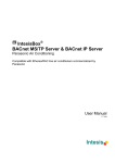
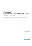
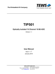
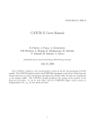
1
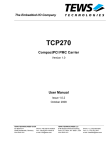
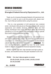
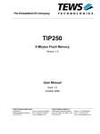
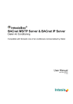
The Embedded I/O Company TPCI270 PMC Carrier for PCI Card Interface Version 1.0 User Manual Issue 1.1 February 2004 D77270801 TEWS TECHNOLOGIES GmbH Am Bahnhof 7 Phone: +49-(0)4101-4058-0 e-mail: [email protected] 25469 Halstenbek / Germany Fax: +49-(0)4101-4058-19 www.tews.com TEWS TECHNOLOGIES LLC 1 E. Liberty Street, Sixth Floor Phone: +1 (775) 686 6077 e-mail: [email protected] Reno, Nevada 89504 / USA Fax: +1 (775) 686 6024 www.tews.com TPCI270-10 This document contains information, which is proprietary to TEWS TECHNOLOGIES GmbH. Any reproduction without written permission is forbidden. PMC Carrier for PCI Card Interface TPCI270-20 PMC Carrier for PCI Card Interface with local 3.3 Volt Generation. TEWS TECHNOLOGIES GmbH has made any effort to ensure that this manual is accurate and complete. However TEWS TECHNOLOGIES GmbH reserves the right to change the product described in this document at any time without notice. TEWS TECHNOLOGIES GmbH is not liable for any damage arising out of the application or use of the device described herein. Style Conventions Hexadecimal characters are specified with prefix 0x, i.e. 0x029E (that means hexadecimal value 029E). For signals on hardware products, an ‚Active Low’ is represented by the signal name with # following, i.e. IP_RESET#. Access terms are described as: W Write Only R Read Only R/W Read/Write R/C Read/Clear R/S Read/Set 2003 - 2004 by TEWS TECHNOLOGIES GmbH Issue Description Date 1.0 Initial Issue May 2003 1.1 Module Version TPCI270-20 added February 2004 TPCI270 User Manual Issue 1.1 Page 2 of 13 Table of Contents 1 2 3 PRODUCT DESCRIPTION ......................................................................................... 5 TECHNICAL SPECIFICATION................................................................................... 6 PMC TO PCI INTERFACE.......................................................................................... 7 3.1 PMC BUSMODE[4:1] Signals .........................................................................................................7 3.2 PCI Signaling Levels and Voltage Keying ....................................................................................7 4 5 INSTALLATION OF A PMC MODULE....................................................................... 8 PIN ASSIGNMENT ..................................................................................................... 9 5.1 5.2 5.3 5.4 5.5 PCI J1 ...............................................................................................................................................9 PCI J2 .............................................................................................................................................10 PMC J11 / P11................................................................................................................................11 PMC J12 / P12................................................................................................................................12 PMC J14 / P14................................................................................................................................13 TPCI270 User Manual Issue 1.1 Page 3 of 13 Table of Figures FIGURE 1-1 : BLOCK DIAGRAM......................................................................................................................5 FIGURE 2-1 : TECHNICAL SPECIFICATION...................................................................................................6 FIGURE 3-1 : PMC VOLTAGE KEYING ...........................................................................................................7 FIGURE 4-1 : INSTALLATION OF A PMC MODULE .......................................................................................8 FIGURE 5-1 : PCI J1 PIN ASSIGNMENT .........................................................................................................9 FIGURE 5-2 : PCI J2 PIN ASSIGNMENT .......................................................................................................10 FIGURE 5-3 : PMC J11/P11 PIN ASSIGNMENT............................................................................................11 FIGURE 5-4 : PMC J12/P12 PIN ASSIGNMENT............................................................................................12 FIGURE 5-5 : PMC J14/P14 PIN ASSIGNMENT............................................................................................13 TPCI270 User Manual Issue 1.1 Page 4 of 13 1 Product Description The TPCI270 is a standard 33 MHz, 32 bit PCI Carrier for a single PMC Card that provides PMC front I/O and PMC P14 rear I/O. This PCI to PMC adapter allowing to build up modular, flexible and cost effective I/O solutions with PMC devices in standard PCI systems. The TPCI270 could use as a mechanical adaptor to connect a standard PMC module in standard PCI systems. The TPCI270 can operate with 3.3V and 5.0V PCI I/O signaling voltage for I/O. This guaranties compatibility with nearly all PC main boards. The TPCI270-20 provides a local 3.3V Generation with a typical current limit of 2A for PC mainboards that do not support 3.3V as PCI supply voltage. The TPCI270 supports standard PMC front I/O and PMC P14 rear I/O routed to a standard VG-64 connector. The I/O mapping of P14 complies to the “VITA-35 PMC P4 to VME-P2-Rows-A,C” mapping. The PMC power lines are blocked by a set of capacitors. The operating temperature range is -40°C to +85°C. Figure 1-1 : Block Diagram TPCI270 User Manual Issue 1.1 Page 5 of 13 2 Technical Specification PCI Interface PCI 2.2 compliant interface, 33 MHz, 32 bit PCI I/O Signaling Voltage 3.3V or 5.0V PMC Slots 1 I/O Access Front panel I/O P14 I/O via VG-64 Connector 3.3 Volt Supply for PMC Module TPCI270-10: depends on host system TPCI270-20: local 3.3V supply, typical current limit 2A Power Requirements without PMC Module 10 mA typical @ V I/O DC Additional power is required by the PMC module Temperature Range Operating Storage MTBF 592000 h Weight 95 g Size 170 x 107 mm Humidity 5 – 95 % non- condensing – 40°C to + 85°C – 40°C to + 85°C Figure 2-1 : Technical Specification TPCI270 User Manual Issue 1.1 Page 6 of 13 3 PMC to PCI Interface The TPCI270 is a mechanical adaptor to connect a standard PMC module in PCI PC systems. As such, it is a passive adapter board and has no PCI-to-PCI bridge. The PCI bus is connected directly to the PMC card. 3.1 PMC BUSMODE[4:1] Signals The BUSMODE[4:1]# signals are unique to IEEE1386 (PMC) and are not found in the PCI specification. They allow a host to identify the CMC card as a PMC card or some other type. The TPCI270 only supports PMC cards. This “PMC only” configuration is provided by pulling up BUSMODE2#, and pulling down BUSMODE3# and BUSMODE4#. A PMC card will decode BUSMODE[4:2]# and put a logic “0” onto BUSMODE1#, that is used by the TPCI270 as PESENT[2:1]# signal. 3.2 PCI Signaling Levels and Voltage Keying PCI and PMC specification both specify 5V and 3.3V signaling voltage. To prevent a PMC to be put onto a mainboard with a different PCI signaling voltage, the PMC defines voltage-keying by pins and holes. PMC cards that support only 5V PCI signaling voltage provide a single keying hole for the 5V keying pin. A 3.3V only PMC provides just the keying hole for the 3.3V keying pin. Universal PMC cards, which can handle 3.3V and 5VPCI signaling voltage, have keying holes for both voltage keying pins. As factory default, the TPCI270 is assembled with the 5V keying pin. Before mounting a PMC onto the TPCI270, make sure that your PCI system and the PMC have the same PCI signaling voltage. If you want to plug a 3.3V only PMC onto the TPCI270, first make sure that your PCI bus works with 3.3V signaling voltage, and then remove the keying pin of the TPCI270 from the 5V location and assemble it in the 3.3V location. WARNING! If PMC modules are plugged into a PCI environment that I/O signaling voltage does not match, damage to the equipment could occur, voiding product warranties. Figure 3-1 : PMC Voltage Keying TPCI270 User Manual Issue 1.1 Page 7 of 13 4 Installation of a PMC Module Before installing a PMC, be sure that the power supply for the TPCI270 is turned off. The component is an Electrostatic Sensitive Device (ESD). Use an anti-static mat connected to a wristband when handling or installing the components. The PMC is mounted to the TPCI270 prior to installation within the chassis. If the PMC has a front panel, install the PMC at an angle so that the PMC front panel penetrates the PC card front panel cutout. Then rotate down to mate with the PMC connectors on the TPCI270. If the PMC has no front panel, simply plug in the PMC. After the PMC has been installed, it can be secured on the TPCI270. This is normally necessary only in vibration or shock environments. Use the mounting screws delivered with the PMC to secure it on the TPCI270. There are four mounting locations, two into the PMC mounting bezel and two for the standoffs near the PMC bus connectors. WARNING! The TPCI270 is a universal PCI device. It can be plugged into a slot which uses either 5V or 3.3V PCI signaling voltage. Take care that your PMC and the PCI environment have the same PCI signaling voltage. If PMC modules are plugged into a PCI environment, and the I/O signaling voltages do not match, damage to the equipment could occur, voiding product warranties. Figure 4-1 : Installation of a PMC Module TPCI270 User Manual Issue 1.1 Page 8 of 13 5 Pin Assignment 5.1 PCI J1 Pin Signal Pin Signal 1 TRST# 32 AD[16] 2 +12V 33 +3.3V 3 TMS 34 FRAME# 4 TDI 35 GND 5 +5V 36 TRDY# 6 INTA# 37 GND 7 INTC# 38 STOP# 8 +5V 39 +3.3V 9 Reserved 40 Reserved 10 V (I/O) 41 Reserved 11 Reserved 42 GND 12 KEYWAY 43 PAR 13 KEYWAY 44 AD[15] 14 3.3Vaux 45 +3.3V 15 RST# 46 AD[13] 16 V (I/O) 47 AD[11] 17 GNT# 48 GND 18 GND 49 AD[09] 19 PME# 50 KEYWAY 20 AD[30] 51 KEYWAY 21 +3.3V 52 C/BE[0]# 22 AD[28] 53 +3.3V 23 AD[26] 54 AD[06] 24 GND 55 AD[04] 25 AD[24] 56 GND 26 IDSEL 57 AD[02] 27 +3.3V 58 AD[00] 28 AD[22] 59 V (I/O) 29 AD[20] 60 REQ64# 30 GND 61 +5V 31 AD[18] 62 +5V Figure 5-1 : PCI J1 Pin Assignment Not all signals are used by the TPCI270. TPCI270 User Manual Issue 1.1 Page 9 of 13 5.2 PCI J2 Pin Signal Pin Signal 1 -12V 32 AD[17] 2 TCK 33 C/BE[2]# 3 GND 34 GND 4 TDO 35 IRDY# 5 +5V 36 +3.3V 6 +5V 37 DEVSEL# 7 INTB# 38 GND 8 INTD# 39 LOCK# 9 PRSNT1# 40 PERR# 10 Reserved 41 +3.3V 11 PRSNT2# 42 SERR# 12 KEYWAY 43 +3.3V 13 KEYWAY 44 C/BE[1]# 14 Reserved 45 AD[14] 15 GND 46 GND 16 CLK 47 AD[12] 17 GND 48 AD[10] 18 REQ# 49 M66EN 19 V (I/O) 50 KEYWAY 20 AD[31] 51 KEYWAY 21 AD[29] 52 AD[08] 22 GND 53 AD[07] 23 AD[27] 54 +3.3V 24 AD[25] 55 AD[05] 25 +3.3V 56 AD[03] 26 C/BE[3]# 57 GND 27 AD[23] 58 AD[01] 28 GND 59 V (I/O) 29 AD[21] 60 ACK64# 30 AD[19] 61 +5V 31 +3.3V 62 +5V Figure 5-2 : PCI J2 Pin Assignment TPCI270 User Manual Issue 1.1 Page 10 of 13 5.3 PMC J11 / P11 Pin Signal Signal Pin 1 TCK -12V 2 3 GND INTA# 4 5 INTB# INTC# 6 7 BUSMODE1# +5V 8 9 INTD# PCI-RSVD 10 11 GND 3.3Vaux 12 13 CLK GND 14 15 GND GNT# 16 17 REG# +5V 18 19 V (I/O) AD[31] 20 21 AD[28] AD[27] 22 23 AD[25] GND 24 25 GND C/BE[3]# 26 27 AD[22] AD[21] 28 29 AD[19] +5V 30 31 V (I/O) AD[17] 32 33 FRAME# GND 34 35 GND IRDY# 36 37 DEVSEL# +5V 38 39 GND LOCK# 40 41 PCI-RSVD PCI-RSVD 42 43 PAR GND 44 45 V (I/O) AD[15] 46 47 AD[12] AD[11] 48 49 AD[09] +5V 50 51 GND C/BE[0]# 52 53 AD[06] AD[05] 54 55 AD[04] GND 56 57 V (I/O) AD[03] 58 59 AD[02] AD[01] 60 61 AD[00] +5V 62 63 GND REQ64# 64 Figure 5-3 : PMC J11/P11 Pin Assignment TPCI270 User Manual Issue 1.1 Page 11 of 13 5.4 PMC J12 / P12 Pin Signal Signal Pin 1 +12V TRST# 2 3 TMS TDO 4 5 TDI GND 6 7 GND PCI-RSVD 8 9 PCI-RSVD PCI-RSVD 10 11 BUSMODE2# +3.3V 12 13 RST# BUSMODE3# 14 15 +3.3V BUSMODE4# 16 17 PME# GND 18 19 AD[30] AD[29] 20 21 GND AD[26] 22 23 AD[24] +3.3V 24 25 IDSEL AD[23] 26 27 +3.3V AD[20] 28 29 AD[18] GND 30 31 AD[16] C/BE[2]# 32 33 GND PMC-RSVD 34 35 TRDY# +3.3V 36 37 GND STOP# 38 39 PERR# GND 40 41 +3.3V SERR# 42 43 C/BE[1]# GND 44 45 AD[14] AD[13] 46 47 M66EN AD[10] 48 49 AD[08] +3.3V 50 51 AD[07] PMC-RSVD 52 53 +3.3V PMC-RSVD 54 55 PMC-RSVD GND 56 57 PMC-RSVD PMC-RSVD 58 59 GND PMC-RSVD 60 61 ACK64# +3.3V 62 63 GND PMC-RSVD 64 Figure 5-4 : PMC J12/P12 Pin Assignment TPCI270 User Manual Issue 1.1 Page 12 of 13 5.5 PMC J14 / P14 Pin Signal Signal Pin 1 I/O 1 I/O 2 2 3 I/O 3 I/O 4 4 5 I/O 5 I/O 6 6 7 I/O 7 I/O 8 8 9 I/O 9 I/O 10 10 11 I/O 11 I/O 12 12 13 I/O 13 I/O 14 14 15 I/O 15 I/O 16 16 17 I/O 17 I/O 18 18 19 I/O 19 I/O 20 20 21 I/O 21 I/O 22 22 23 I/O 23 I/O 24 24 25 I/O 25 I/O 26 26 27 I/O 27 I/O 28 28 29 I/O 29 I/O 30 30 31 I/O 31 I/O 32 32 33 I/O 33 I/O 34 34 35 I/O 35 I/O 36 36 37 I/O 37 I/O 38 38 39 I/O 39 I/O 40 40 41 I/O 41 I/O 42 42 43 I/O 43 I/O 44 44 45 I/O 45 I/O 46 46 47 I/O 47 I/O 48 48 49 I/O 49 I/O 50 50 51 I/O 51 I/O 52 52 53 I/O 53 I/O 54 54 55 I/O 55 I/O 56 56 57 I/O 57 I/O 58 58 59 I/O 59 I/O 60 60 61 I/O 61 I/O 62 62 63 I/O 63 I/O 64 64 Figure 5-5 : PMC J14/P14 Pin Assignment TPCI270 User Manual Issue 1.1 Page 13 of 13