1
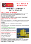
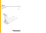
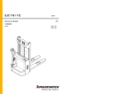
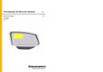
Diesel Particulate Filter
12.07 -
Operating Instructions
G
51098680
DFG 316-320
08.10
DFG 316s-320s
DFG 425-435
DFG 425s-435s
F
Foreword
The present ORIGINAL OPERATING INSTRUCTIONS are designed to provide
sufficient instruction for the safe operation of the industrial truck. The information is
provided clearly and concisely. The chapters are arranged by letter. Each chapter
starts with page 1. The page identification consists of a chapter letter and a page
number.
For example: Page B 2 is the second page in chapter B.
The operating instructions detail different truck models. When operating and servicing
the truck, make sure that the instructions apply to your truck model.
The operating instructions detail different truck models. When operating and servicing
the truck, make sure that the instructions apply to your truck model.
Safety instructions and important explanations are indicated by the following
graphics:
Safety instructions and important explanations are indicated by the following
graphics:
F
Used before safety instructions which must be observed to avoid danger to
personnel.
M
Z
Used before notices which must be observed to avoid material damage.
Used before notices and explanations.
Used before safety instructions which must be observed to avoid danger to
personnel.
Used before notices which must be observed to avoid material damage.
Used before notices and explanations.
t Used to indicate standard equipment.
t Used to indicate standard equipment.
o Used to indicate optional equipment.
o Used to indicate optional equipment.
Our trucks are subject to ongoing development. Jungheinrich reserves the right to
alter the design, equipment and technical features of the truck. No guarantee of
particular features of the truck should therefore be inferred from the present operating
instructions.
Our trucks are subject to ongoing development. Jungheinrich reserves the right to
alter the design, equipment and technical features of the truck. No guarantee of
particular features of the truck should therefore be inferred from the present operating
instructions.
Copyright
Copyright
Copyright of these operating instructions remains with JUNGHEINRICH AG.
Copyright of these operating instructions remains with JUNGHEINRICH AG.
Jungheinrich Aktiengesellschaft
Jungheinrich Aktiengesellschaft
Am Stadtrand 35
22047 Hamburg - GERMANY
Am Stadtrand 35
22047 Hamburg - GERMANY
Telephone: +49 (0) 40/6948-0
Telephone: +49 (0) 40/6948-0
www.jungheinrich.com
www.jungheinrich.com
0810.GB
0810.GB
M
Z
Foreword
0810.GB
0810.GB
Table of contents
2
3
4
5
6
6
7
8
9
10
1
2
3
4
5
5.1
5.2
6
6.1
7
Overview DFG 316-320 ......................................................................
Overview DFG 316s-320s ...................................................................
Overview DFG 425-435 ......................................................................
Overview DFG 425s-435s ...................................................................
Functional description .........................................................................
Regeneration suppression: .................................................................
Meaning of the indicator lamps and relevant actions ..........................
Safety instructions ...............................................................................
Consumables ......................................................................................
Maintenance / Care / Repair ...............................................................
2
3
4
5
6
6
7
8
9
10
0810.GB
Overview DFG 316-320 ......................................................................
Overview DFG 316s-320s ...................................................................
Overview DFG 425-435 ......................................................................
Overview DFG 425s-435s ...................................................................
Functional description .........................................................................
Regeneration suppression: .................................................................
Meaning of the indicator lamps and relevant actions ..........................
Safety instructions ...............................................................................
Consumables ......................................................................................
Maintenance / Care / Repair ...............................................................
0810.GB
1
2
3
4
5
5.1
5.2
6
6.1
7
Table of contents
I1
I1
I2
I2
0810.GB
0810.GB
Diesel Particle Filter
Diesel Particle Filter
Diesel Particle Filter
Diesel Particle Filter
All maintenance and repair work must be performed by expert personnel of the manufacturer.
All maintenance and repair work must be performed by expert personnel of the manufacturer.
0810.GB
The filter system must only be used for the exhaust gas filtering of diesel engines.
The manufacturer shall accept no liability if the product is not used in the manner intended. The User's Manual of the vehicle, the general accident prevention regulations
and all other generally recognised rules pertaining to safety and industrial health are
to be complied with at all times.
1
1
1
Overview DFG 316-320
1
Wire harness
Hose line
Metal line
Wire harness
Hose line
Metal line
0810.GB
1 Indicators and switches for regeneration
suppression
2 Reservoir indicator connection as per wiring
diagram
3 Diesel return line to fuel tank
4 Metering pump
5 Additive tank with additive filter
6 Additive tank ventilation/discharge
7 Diagnostic connector
8 HJS-ECU
9 Air mass sensor
10 Connection as per wiring diagram (term. 15/30)
11 Differential pressure sensor
12 Diesel Particle Filter
13 Pressure measurement point before filter
14 Temperature gauge
15 Pressure measurement point after filter
16 Heating power supply
17 Exhaust outlet pipe
18 Earth strap
19 100 amp fuse
20 Connection as per wiring diagram (term. 31)
2
Overview DFG 316-320
2
2
Overview DFG 316s-320s
2
Wire harness
Hose line
Metal line
Overview DFG 316s-320s
Wire harness
Hose line
Metal line
0810.GB
1 Indicators and switches for regeneration
suppression
2 Reservoir indicator connection as per wiring
diagram
3 Diesel return line to fuel tank
4 Metering pump
5 Additive tank with additive filter
6 Additive tank ventilation/discharge
7 Diagnostic connector
8 HJS-ECU
9 Air mass sensor
10 CAN and terminal 15 connected, in accordance
with wiring diagram
11 Differential pressure sensor
12 Diesel Particle Filter
13 Pressure measurement point before filter
14 Temperature gauge
15 Pressure measurement point after filter
16 Heating power supply
17 Exhaust outlet pipe
18 Earth strap
19 Connection as per wiring diagram (term. 30/31)
20 100 amp fuse
3
3
3
Overview DFG 425-435
3
Wire harness
Hose line
Metal line
Wire harness
Hose line
Metal line
0810.GB
1 Indicators and switches for regeneration
suppression
2 Reservoir indicator connection as per wiring
diagram
3 Diesel return line to fuel tank
4 Metering pump
5 Additive tank with additive filter
6 Additive tank ventilation/discharge
7 Diagnostic connector
8 HJS-ECU
9 Air mass sensor
10 Connection as per wiring diagram (term. 15/31)
11 Differential pressure sensor
12 Diesel Particle Filter
13 Pressure measurement point before filter
14 Temperature gauge
15 Pressure measurement point after filter
16 Heating power supply
17 Exhaust outlet pipe
18 Earth strap
19 100 amp fuse
4
Overview DFG 425-435
4
4
Overview DFG 425s-435s
4
Wire harness
Hose line
Metal line
Overview DFG 425s-435s
Wire harness
Hose line
Metal line
0810.GB
1 Indicators and switches for regeneration
suppression
2 Reservoir indicator connection as per wiring
diagram
3 Diesel return line to fuel tank
4 Metering pump
5 Additive tank with additive filter
6 Additive tank ventilation/discharge
7 Diagnostic connector
8 HJS-ECU
9 AGR connection as per wiring diagram
10 CAN and terminal 30 connected, in accordance
with wiring diagram
11 Differential pressure sensor
12 Diesel Particle Filter
13 Pressure measurement point before filter
14 Temperature gauge
15 Pressure measurement point after filter
16 Heating power supply
17 Exhaust outlet pipe
18 Earth strap
19 Connection as per wiring diagram (term. 30/31)
20 100 amp fuse
5
5
5
Functional description
5
Functional description
The filter system consists of a diesel particle filter using sintered metal technology
and a fully automatic regeneration unit. The latter is able to burn off the soot trapped
by the filter without intervention by the driver and to do so under any engine operating
conditions. Once an adequate quantity of soot has built up in the filter, the electronic
control unit automatically triggers regeneration. To ensure combustion of the soot is
complete, with as good as no residue, and conducted in very short time, an additive
that lowers the ignition temperature and increases the burn-off speed of the soot is
added to the diesel by the automatic dosing system.
When the truck starts up after fuelling, the system automatically detects the amount
of fuel added and meters the corresponding the amount of additive into the fuel return
line. A slightly clicking noise can be heard from the metering pump.
When the truck starts up after fuelling, the system automatically detects the amount
of fuel added and meters the corresponding the amount of additive into the fuel return
line. A slightly clicking noise can be heard from the metering pump.
The following points must be observed:
The following points must be observed:
M
As a self-test, the two indicator lamps are illuminated for approx. 10 seconds when
the ignition is switched on. If one or both of these indicator lamps does not light up
during this test, there is a fault in the system. Contact expert personnel of the manufacturer.
M
As a self-test, the two indicator lamps are illuminated for approx. 10 seconds when
the ignition is switched on. If one or both of these indicator lamps does not light up
during this test, there is a fault in the system. Contact expert personnel of the manufacturer.
M
If one indicator lamp is defective, the other lamp flashes continuously. The meaning
of these indicator lamps is described in detail on the following page.
M
If one indicator lamp is defective, the other lamp flashes continuously. The meaning
of these indicator lamps is described in detail on the following page.
M
Z
Regeneration must be conducted outdoors!
Regeneration must be conducted outdoors!
However, if the truck is located indoors (warehouse etc.) at the time of the automatic
regeneration, there is a regeneration suppression option.
M
Z
5.1
Regeneration suppression:
5.1
Regeneration suppression:
Approx. 5 minutes before automatic regeneration starts the button (picture) begins to flash. During this time the operator can leave the indoor
area in the truck. If this proves impossible, the operator can press the
button; this activates a 20 minute regeneration suppression which gives
the operator more time to vacate the truck from the indoor area.
6
This process can only be repeated once. The third time the flashing light cannot be
suppressed by pressing the button. After approx. 5 minutes the system regenerates
fully automatically to protect itself.
0810.GB
M
This process can only be repeated once. The third time the flashing light cannot be
suppressed by pressing the button. After approx. 5 minutes the system regenerates
fully automatically to protect itself.
0810.GB
M
However, if the truck is located indoors (warehouse etc.) at the time of the automatic
regeneration, there is a regeneration suppression option.
6
5.2
Meaning of the indicator lamps and relevant actions
5.2
Meaning of the indicator lamps and relevant actions
The filter system must only be operated on by the manufacturer’s specialist service
engineers.
The filter system must only be operated on by the manufacturer’s specialist service
engineers.
Start phase - Both indicator lamps lit constantly approx. 10 sec.:
Start phase - Both indicator lamps lit constantly approx. 10 sec.:
Filter system check
Filter system check
If neither of the indicator lamps lights up during this test, there is a
fault in the system. Contact expert personnel of the manufacturer.
If neither of the indicator lamps lights up during this test, there is a
fault in the system. Contact expert personnel of the manufacturer.
Yellow indicator lamp flashing:
Yellow indicator lamp flashing:
Conduct regeneration cycle
Conduct regeneration cycle
If the truck is permanently used for short journeys the filter system
may not fully regenerate. In this case, regeneration must be conducted as follows: leave the stationary industrial truck running at
governed (maximum no-load) speed for 10 minutes so that the
system performs regeneration. If the indicator lamp does not go
out after repeating regeneration once, contact expert personnel of
the manufacturer.
Yellow indicator lamp lit constantly:
Yellow indicator lamp lit constantly:
Automatic regeneration during operation
Automatic regeneration during operation
When automatic regeneration is being performed, the vehicle must
not be switched off. Normal vehicle operation should be continued
until the yellow indicator lamp goes out.
When automatic regeneration is being performed, the vehicle must
not be switched off. Normal vehicle operation should be continued
until the yellow indicator lamp goes out.
M
Regeneration must be conducted outdoors!
M
Serious fault -> The system may be damaged. Contact expert
personnel of the manufacturer!
Red indicator lamp flashing:
M
Regeneration must be conducted outdoors!
M
Serious fault -> The system may be damaged. Contact expert
personnel of the manufacturer!
A serious fault has arisen or the system has become damaged.
A serious fault has arisen or the system has become damaged.
Red indicator lamp lit constantly:
Red indicator lamp lit constantly:
M
Fault - Contact expert personnel of the manufacturer!
Fault - Contact expert personnel of the manufacturer!
An error has occurred or the filter system has broken down. Contact expert personnel of the manufacturer.
0810.GB
An error has occurred or the filter system has broken down. Contact expert personnel of the manufacturer.
0810.GB
M
Red indicator lamp flashing:
7
7
6
Safety instructions
6
– To ensure safe operation the filter system must only be operated in accordance
with the operator manual.
– The legal and safety regulations of relevance to operation must be observed at all
times when using the system. The same applies to the use of accessories.
– The filter system must only be serviced or assembled by the manufacturer’s specialist service engineers.
F
The filter housing of the filter system is heated during operation and can burn
if touched. The hot filter housing poses a fire or ignition hazard. The vehicle must always be parked in a location that ensures the diesel particulate filter does not come
into contact with easily inflammable materials (e.g. dry grass).
F
F
F
F
The additive used is detrimental to human health and is subject to special directions
that are listed in detail in the next section entitled "Consumables".
Operating the diesel particle filter in conjunction with the Jungheinrich ISM or
other access systems.
If an access system is used which causes the truck to shut down automatically when
the driver leaves the truck, note the following:
Set the automatic shutdown delay interval to at least 10 minutes to avoid cancelling
a regeneration operation that has already started (continual yellow indicator lamp). If
the interval is set shorter, the driver must remain on the truck while regeneration continues until the yellow indicator lamp goes out.
0810.GB
F
F
F
F
– To ensure safe operation the filter system must only be operated in accordance
with the operator manual.
– The legal and safety regulations of relevance to operation must be observed at all
times when using the system. The same applies to the use of accessories.
– The filter system must only be serviced or assembled by the manufacturer’s specialist service engineers.
8
The filter housing of the filter system is heated during operation and can burn
if touched. The hot filter housing poses a fire or ignition hazard. The vehicle must always be parked in a location that ensures the diesel particulate filter does not come
into contact with easily inflammable materials (e.g. dry grass).
The additive used is detrimental to human health and is subject to special directions
that are listed in detail in the next section entitled "Consumables".
Operating the diesel particle filter in conjunction with the Jungheinrich ISM or
other access systems.
If an access system is used which causes the truck to shut down automatically when
the driver leaves the truck, note the following:
Set the automatic shutdown delay interval to at least 10 minutes to avoid cancelling
a regeneration operation that has already started (continual yellow indicator lamp). If
the interval is set shorter, the driver must remain on the truck while regeneration continues until the yellow indicator lamp goes out.
0810.GB
F
Safety instructions
8
6.1
Consumables
6.1
Consumables
Z
Follow special instructions / consult safety data sheet
Z
Follow special instructions / consult safety data sheet
Identification
M
Identification
R 40
Irreversible damage possible.
R 40
Irreversible damage possible.
R 51
Poisonous for water organisms.
R 51
Poisonous for water organisms.
R 53
May have long-term harmful effect in water.
R 53
May have long-term harmful effect in water.
R 65
Harmful to health:
can cause lung damage if swallowed.
R 65
Harmful to health:
can cause lung damage if swallowed.
R 66
Repeated contact can cause brittle cracked skin.
R 66
Repeated contact can cause brittle cracked skin.
R 67
Vapours can cause drowsiness and numbness.
R 67
Vapours can cause drowsiness and numbness.
S 36
Wear safety clothing during work.
S 36
Wear safety clothing during work.
S 37
Wear appropriate safety gloves.
S 37
Wear appropriate safety gloves.
S 60
This substance and/or its container must be disposed of as
hazardous material.
S 60
This substance and/or its container must be disposed of as
hazardous material.
S 61
Do not release into the environment.
S 61
Do not release into the environment.
M
Seek medical advice immediately and show packaging or label.
Identification
Identification
S 62
Do not induce vomiting if swallowed.
0810.GB
Do not induce vomiting if swallowed.
0810.GB
S 62
Seek medical advice immediately and show packaging or label.
9
9
Maintenance / Care / Repair
7
10
Maintenance / Care / Repair
Any work performed on the filter system, service and repairs must only be carried out
by the manufacturer’s specialist service engineers. Use only spare parts and
materials approved by the manufacturer.
To ensure the long useful life of the filter system always follow the hints and actions
listed for error messages.
To ensure the long useful life of the filter system always follow the hints and actions
listed for error messages.
0810.GB
Any work performed on the filter system, service and repairs must only be carried out
by the manufacturer’s specialist service engineers. Use only spare parts and
materials approved by the manufacturer.
0810.GB
7
10