1
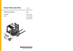
TEL11
INDUSTRIAL DIGITAL
EARTH LEAKAGE CIRCUIT
BREAKER and 3 PHASE
ROTATION TESTER
EARTH
!
DIGITAL INDUSTRIAL ELCB
PHASE ROTATION TESTER
MULTI VOLTAGE (220 to 317 Vac) L-E
FUSE
EARTH
FAULT
CURRENT
CURRENT ADJUST
L1
T
L2
L3
!
L1
L2
OFF
L3
SELECT PHASE
TO EARTH FAULT
DECREASE
T
S
R
AUTO POWER OFF
MENU
SELECT
S
R
CF
VELCB
IELCB
INCREASE
S
R
L1
T
L2
L3
PHASE PRESENCE INDICATOR
MAXIMUM 550Vac L-L
(317Vac L-E)
50Hz sine system only
L2L1L3 L1L2L3
PHASE ROTATION INDICATOR
ENTER
YES
Minimum
Maximum
ON
BATTERY
OK
MODEL : TEL11
USER'S MANUAL
TABLE OF CONTENTS
DESCRIPTION
SAFETY RULES.................................................
SAFETY CHECKS..............................................
DON'T TOUCH...................................................
GENERAL DESCRIPTION.................................
BRIEF PRODUCT DESCRIPTION.....................
OPERATING INSTRUCTIONS...........................
FRONT PANEL LAYOUT....................................
KEYPAD and MAIN KEYS..................................
PRINCIPLE OF HOW IT WORK.........................
PREPARATION FOR USE..................................
REPLACING THE BATTERIES..........................
SPECIFICATIONS..............................................
LIMITED WARRANTY.........................................
PAGE
01
02
02
03
04
05-07
08
09
10-11
12
12
13
14
SAFETY RULES
CAUTION
RISK OF ELECTRIC
SHOCK
This tester has been designed with your safety in mind. However, no
design can completely protect against incorrect use. Electrical circuits
can be dangerous and/or lethal when lack of caution or poor safety
practices are used.
Do not carry out field measurements on either the power system
grounding, during periods of forecast lightning activity, in areas that
encompass the station being measured or of the power network
connected to the station being measured. In the event that lightning
occurs, stop all testing and isolate any temporarily installed test spikes.
Preparations for testing of power system grounding can leave personnel
vulnerable to exposure caused by faults at or fed from the system under
test, transferred potentials from remote test grounds, and inadvertent line
energisations.
While the probability of the occurrence of one of these events is low,
personnel safety will, nevertheless, be enhanced by the following:
When working near high tension systems rubber gloves and shoes
should be worn.
Work on clean, dry crushed rock or an insulating blanket.
Avoid bare hand to hand contact between the tester and extended
test leads.
When using the tester with test leads, ensure that they are safe and
properly authorized
Disconnect the tester from any external circuit when changing the
batteries.
CAUTION
READ THE MANUAL
Follow the instructions in the Manual for every measurement. Read and
understand the general instructions before attempting to use this tester.
-1-
SAFETY CHECK
Before using the tester check the condition of the batteries. This is
done by switching the tester ON.
If the BAT OK led does not light up, the battery need replacing.
Battery and fuse replacement are described later in this user's manual.
When changing the battery, fuses, or removing the cover to access
the internal circuitry, always disconnect the test leads.
When replacing the fuse use only the type specified, 5 X 20mm, 1.0A,
fuse, and insert correctly into the fuse holder.
Double check the switch setting, and lead connections before making
measurements.
DON'T TOUCH
Don't touch exposed wiring, connections or other "Live"
parts of an electrical circuit. If in doubt, check the circuit first for
voltage before touching it.
Do not use cracked of broken test leads.
THIS INSTRUMENT SHOULD ONLY BE USED BY A COMPETENT,
SUITABLY TRAINED PERSON.
REMEMBER
SAFETY IS NO ACCIDENT
CAUTION RISK OF ELECTRIC SHOCK
CAUTION READ THE MANUAL
-2-
GENERAL DESCRIPTION
This Test Instrument is a combined 3 Phases Presence and Rotation
Indicator combined with a 3 Phases Industrial Earth Leakage Tester.
When utilized as a 3 Phase Presence and Rotation Indicator, the
instrument does not use the batteries and can still be utilized if the
batteries are not present or if the batteries are too low.
The 3 phase Presence and Rotation Indicator which is inside the TEL11,
takes it's power from the circuit under test.
The Earth Leakage can be utilized on a Single Phase (up to 317Vac Line
to Earth) or a 3 Phase Powered System (550V Line to Line or Phase to
Phase) with a protective Earth conductor.
The Earth Leakage requires batteries.
When utilized on a single phase, ensure correct connection between Line
and Earth before using the tester.
When utilized on a 3 Phase Powered System, the instrument is then
utilized as a 3 Phases Presence and Rotation Indicator and a Earth
leakage tester (selecting which phase to Earth will be utilized for the
ELCB test).
When utilized on a 3 Phases Powered System, this instrument is a rotary
field indication instrument which display all three phases by lighting up
it's corresponding Lamp. It display the rotation (clockwise or anticlockwise) on a LED.
To test the tripping time or the tripping current of a Eathr Leakage Circuit
Breaker, make sure to connect the earth wire.
This instrument represents the quickest and easiest way for servicing,
repairing and electrical maintenance of 3 phase system with earth
leakage.
With this equipment, you can, before connecting Load to Supply:
On the supply side;
Quickly verify the presence of the three Phases on a 3
Phases Power System.
Confirm the Phase Rotation on a Powered 3 Phase System.
Test the Tripping (disconnection) current and time of the
protections.
-3-
BRIEF PRODUCT DESCRIPTION
This 3 Phases Rotation and Earth Leakage Tester has 4 test leads
which connects to the 4 mm female sockets on the tester.
These Test leads are color coded.
R(L1) =
Red which connects to R on the tester.
S(L2) =
White which connects to S on the tester.
T(L3) =
Blue which connects to T on the tester.
T(L3) =
Blue which connects to T on the tester.
Earth =
Green which connects to Earth on the tester.
On the other side of the test leads are the probes, also color coded.
The Phase Presence Indicator has three neon lamps which are the
Phase Presence indicators;
Neon Lamp for Individual Phase Presence Indication =
Neon Lamp for Individual Phase Presence Indication =
Neon Lamp for Individual Phase Presence Indication =
R(L1)
S(L2)
T(L3)
Please note that any of these Neon lamp will only start to light up if
more than 100Vac is present between any 2 phases.
The Phase Rotation Indicator has;
A LED to display clockwise rotary direction L1L2L3.
A LED to display counter clockwise L2L1L3.
The Earth Leakage Tester comprise of the Phase Selector, which
permit the selection to connect Phase 1 ( L1 or R ) to the earth
Leakage tester, or Phase 2 ( L2 or S), or phase 3 (L3 or T).
The Industrial Earth Leakage Tester injects a fault current between
one of the phase and earth.
When utilized to test on a single phase system, the 3 Phase Presence
and rotation features and indications must be disregarded.
The Selector Switch must be on the R position, and the R(L1) phase
is connected to the Phase(Line), the green socket to Earth.
Neutral wire is not utilized in the testing of the Earth leakage Circuit
Breaker.
-4-
OPERATING INSTRUCTIONS
Determination of the rotary field direction and phase presence
On a 3 Phase System, the sequence of the 3 phases determine the
rotation of a 3 phase motor connected to that system.
The correct 3 Phase Sequence R(L1), S(L2), T(L3) results in a
clockwise rotation of the connected motor.
Connect the Test Leads to the sockets of the Instrument, respecting
the correct color. Red to R(L1), White to S(L2), Blue to T(L3).
Clip the test probes to the three mains phases, R(L1), S(L2), T(L3).
When connecting to a voltage superior to 100V AC, the corresponding
neon lamp will start to glow, indicating the presence of the voltage on
it's corresponding lead (L1, L2, L3 lamps).
If the LED (Right arrow) L1-L2-L3 is illuminated, clockwise rotary field
is present.
If the LED(Left arrow) L2-L1-L3 is illuminated, a counter clockwise
rotary field is present.
-5-
Determination of the disconnection sensitivity of the Earth
Leakage Circuit Breaker
Connect the Earth lead from the tester to the Earth connection on the
system. Using the rotary switch, select which phase you want to test
from, connect the phases.
Turn Instrument "ON" by pressing the "TEST-ON" button.
The L.C.D. display will come to the following Screen.
* - Instantaneous
- Time Delay
Push Select to change Selection
to Instantaneous, then Press "TEST " to accept.
Dial Starting
Current. 123mA
Dial the Starting Current of the
Instantaneous Test using the Current Adjust Knob .
0°
Positive
Start Edge
Select the Positive or Negative
Start Edge using the Select Button.
Connect Leads
to Earth & Phase
Connect Leads to Earth and Phase.
Testing will start Automatically when voltage is detected .
V=317V
I=127mA
Test In Progress. The Voltage between leads was 317V
before testing started and I=127mA
V=317V I=140mA Hold®TRP
TRP= Tripped, Display on Hold
Tripped at 140mA, on - edge of signal.
-6-
Determination of the disconnection time of the Earth Leakage
Circuit Breaker
Connect the Earth lead from the tester to the Earth connection on the
system. Using the rotary switch, select which phase you want to test
from, connect the phases.
Turn Instrument "ON" by pressing the "TEST-ON" button.
The L.C.D. display will come to the following Screen.
- Instantaneous
* - Time Delay
Push Select to change Selection
to Instantaneous, then Press "TEST" to accept.
Dial Testing
Current. 125mA
Dial the Testing Current of the
Instantaneous Test using the Current Adjust Knob .
0°
Positive
Start Edge
Select the Positive or Negative
Start Edge using the Select Button.
Connect Leads
to Earth & Phase
Connect Leads to Earth and Phase. When voltage is
detected, Testing will start Automatically .
V=317V T= 4.020s
I=125mA
Test In Progress since 4.020s. The Voltage between leads was 317V
before testing started and Constant current is 125mA.
V=317V+ T= 6.435s
I=125mA Hold®TRP
TRP= Tripped, Display on Hold
at 6.435s Tripped on + edge of signal.
-7-
!
EARTH
FUSE
DISPLAY
EARTH CONNECTION FEMALE SOCKET
-8-
MODEL : TEL11
Minimum
Maximum
ON
INCREASE
OFF
BATTERY
OK
MAXIMUM 550Vac L-L
(317Vac L-E)
50Hz sine system only
SELECT PHASE
TO EARTH FAULT
R
L2
S
T
L3
L3
T
T
L2L1L3 L1L2L3
PHASE ROTATION INDICATOR
PHASE PRESENCE INDICATOR
L1
L3
L2
L1
L2
S
S
NEONS LIGHTS
FOR PHASE PRESENCE
ENTER
YES
CURRENT ADJUST
!
L1
R
R
ROTARY
SELECTOR
DECREASE
MENU
SELECT
CF
VELCB
IELCB
EARTH
FAULT
CURRENT
FUSE
LOCATING PIN
FEMALE COLOR
CODED SOCKETS
(for Phase Connections)
AUTO POWER OFF
MULTI VOLTAGE (220 to 317 Vac) L-E
DIGITAL INDUSTRIAL ELCB
PHASE ROTATION TESTER
VOLTAGE APPLIED
ONTO ELCB TESTER
INDICATOR
FRONT PANEL LAYOUT
LEDS LIGHTS
FOR PHASE ROTATION
BATTERY OK
INDICATOR
KEYPAD and MAIN KEYS
select between types of tests
Instantaneous (checking the tripping ) current
or
Time Delay (checking the tripping time)
Turn the TESTER
OFF
MENU
SELECT
OFF
CURRENT ADJUST
DECREASE
ENTER
YES
INCREASE
Maximum
Minimum
ON
Turn the TESTER
ON
Accept the selection
Adjust the Starting Current (Instantaneous)
or
Adjust the ConstantCurrent (Time Delay)
-9-
PRINCIPLE OF HOW IT WORK
The tester has two separate circuits:
One is for the 3 Phase Presence and Rotation indicator, the other
is for the Earth leakage Circuit Breaker Tester.
The first circuit is the 3 Phase presence indicator, which is shown by
the neon lamps and the three phase sequence indicator by leds.
3 Phase Presence and Rotation indicator:
This circuit derive it's power from the system under test.
This circuit does not require the user of battery and is self powered
through resistors.
3 Phase Presence Indication circuit:
This circuit uses neon lamps to indicate if a phase is present.
These neon lamps are connected in series with a limiting resistor.
Neon lamps will lights up when the voltage across any two phases is
more than 100Vac.
3 Phase sequence indicator circuit:
This circuit has an analog and a digital part. The analog signals are
shaped then compared to a set of references. These results are
digitally compared to give the results on the indicating LEDs.
-10-
Earth leakage Circuit Breaker Tester
At switch-ON, the circuit is powered up.
A low battery detection pickup circuit, with a Power On indicator LED
is also present.
This LED indicate that the batteries are ok and it will lights up when
the batteries are ok.
Should this led not lights up, replace the batteries.
Once the Earth Leakage Circuit Breaker is turned-ON, the first menu
will indicate that the instrument is ready.
Basically, this instrument measure the voltage Line to Earth or
between the selected phase to Earth.
This is not the Line to Line voltage.
The tester also has a computer controlled constant current source,
from which the test fault current is taken from.
This instrument reproduce a perfect 50Hz current sinewave, wich is
independant from the shape of the voltage.
-11-
PREPARATION FOR USE
Fuses
In doubt, check the fuses using a ohm meter.
Please note that the Earth Leakage Tester will not indicate any
voltage, should the fuses be blown.
Should the fuse be blown, the Current Led will also not lit.
Test Leads
Check the test leads for defects or cracks. Replace if cracked or
damaged. Only replace with the same type
Cleaning
Use a damp cloth to clean the case. Do not use chemicals
Batteries
Checking the battery is automatically done, once the tester is
switched "ON". Should the battery OK led not lit, replace the batteries.
REPLACING THE BATTERIES
Prior to battery replacement always disconnect the instrument from
the circuit to which it's connected.
Remove the test leads from the instrument.
Remove the back cover to access the battery compartment.
Remove all the bad batteries from the battery compartment and
dispose properly of that batteries (see your local disposal facilities
related to disposal of batteries).
Only replace with 8 new batteries of the following type 1.5 V, C type.
Re-insert the (batteries) back cover onto the instrument and tighten
the screw.
FUSES REPLACEMENT
Unscrew the front fuse cover and replace the faulty fuse with the
same type, then screw the fuse cover back into place correctly
-12-
SPECIFICATIONS
ELECTRICAL
Determination of the Phase Presence
Nominal Voltage for Phase Presence Indication (the voltage required for
the neon lamps L1, L2, L3 to lit up).... From 100Vac to 450Vac.
Frequency Range .............................. From 10Hz to 400Hz.
Determination of the Phases Rotary Field Direction:
Direction (the voltage required to have the direction LEDs L1-L2-L3 or
L2-L1-L3 to indicates)......................... From 100 to 450Vac.
Frequency Range .............................. From 2Hz to 400Hz.
Protection
Over Load........................................... 550V (between all terminals).
Over Voltage ...................................... Class III - 450V towards ground.
ENVIRONMENTAL
Operating temperature Range
Storage Temperature
Earth Leakage
Current Settings
Current Selection
Phase Start Selection(*)
Over-Temperature Protection(*)
Phase Polarity Trip Indicator(*)
Operating Voltage ( L-E )
(*)Referenced to Earth
Timer Resolution
Timer Accuracy
Current Accuracy
Current Resolution
Voltmeter Accuracy (50Hz)
-15 °C to + 55 °C
-20 °C to + 70 °C
999mAac / 50Hz
Knob
0° and 180°
Yes
Yes
110Vac to 317Vac
1mS (Max Time = 99.99S)
1mS ±4mS
±3% ±4mA
1mA
50-350 Vac = ±3%±2V
350-550Vac = ±7%±3V
1V
8 x C batteries
Bat OK Led = Vbat >9V
Voltmeter Resolution
Batteries
Maximum Current Specified at 317Vac / 50Hz
CLEANING
Clean the instrument case with an anti-static cleaner and wipe with dry
cloth.
-13-
LIMITED WARRANTY
We warrant the product manufactured by us to be free from
defective material or factory workmanship and agree to repair or
replace this product which, under normal use and service,
disclose the defect to be the fault of our manufacturing, with no
charge for parts and service. If we are unable to repair or replace
this product, we will make a full refund of the purchase price.
Consult the user's manual for proper instruction regarding use
of this instrument.
Our obligation under this warranty is limited to repairing,
replacing or making refund of this test equipment which proves
to be defective within twenty four months from the date of
original purchase.
This warranty does not apply to any of our products which have
been repaired or altered by unauthorized persons in any way so
as, in our sole judgement, to injure their stability or reliability, or
which have been subject to misuse, abuse, misapplication,
negligence or accident or which have had the serial numbers
altered, defaced or removed.
Accessories, not of our manufacture used with this product, are
not covered by this warranty.
All warranties implied by law are hereby limited to a period of
twenty four months, and the provisions of the warranty are
expressly in lieu of any other warranties expressed or implied.
The purchaser agrees to assume all liability for any damages or
bodily injury which may result from the use or misuse of the
product by the purchaser, or it's user, his employees, or others,
and the remedies provided for in this warranty are expressly in
lieu of any other liability we may have including incidental or
consequential damages.
We reserve the right to discontinue models at any time, or
change specification, price or design, without notice and without
incurring any obligation.
-14-