1
DOC026.53.00817
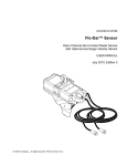
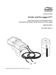
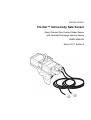
Flo-Dar™ Intrinsically Safe Sensor
Open Channel Non-Contact Radar Sensor
with Optional Surcharge Velocity Sensor
USER MANUAL
March 2011, Edition 2
Table of contents
Section 1 Specifications .................................................................................................................... 3
Section 2 General information ......................................................................................................... 5
2.1 Safety information ........................................................................................................................ 5
2.1.1 Use of hazard information................................................................................................... 5
2.1.2 Precautionary labels ........................................................................................................... 5
2.1.3 Confined space precautions ............................................................................................... 6
2.2 Product overview ......................................................................................................................... 7
Section 3 Installation.......................................................................................................................... 9
3.1 Precautions for hazardous location installations.......................................................................... 9
3.1.1 Intrinsically safe installation requirements .......................................................................... 9
3.1.2 Hazardous location control drawings .................................................................................. 9
3.2 Sensor installation...................................................................................................................... 10
3.2.1 Install the frame on the wall .............................................................................................. 10
3.3 Electrical installation .................................................................................................................. 10
3.3.1 Wiring safety information .................................................................................................. 10
3.3.2 Electrical installation in a hazardous location ................................................................... 11
3.3.2.1 Install the barrier ...................................................................................................... 11
3.3.2.2 Wiring to the barrier.................................................................................................. 13
3.3.2.3 Connection to the logger or controller ...................................................................... 15
3.4 Approved Flo-Dar installation drawings ..................................................................................... 15
Section 4 Maintenance .................................................................................................................... 19
4.1 Cleaning the instrument ............................................................................................................. 20
1
Table of contents
2
Section 1
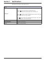
Specifications
Specifications are subject to change without notice.
General
cETLus Listed, ATEX EC-Type Certified
Flo-Dar:
II2G, Ex ib IIB T4 Gb, ITS10ATEX27065X, and
Class I, Zone 1 AEx ib IIB T4 Gb and Class I, Zone 1 Ex ib IIB T4 Gb
Certification
Barrier:
II(2)G, [Ex ib Gb] IIB, ITS10ATEX27042X, and Class I, Zone 1 [AEx
ib Gb] IIB and Class I, Zone 1 [Ex ib Gb] IIB
SVS:
II2G, Ex ib IIB T4 Gb, ITS10ATEX27043X, and Class I, Zone 1 AEx ib
IIB T4 Gb and Class I, Zone 1 Ex ib IIB T4 Gb
Operating temperature
–10 to 50 °C (14 to 122 °F)
Storage temperature
–40 to 60 °C (–40 to 140 °F)
Altitude
4000 m (13,123 ft) maximum
3
Specifications
4
Section 2
General information
2.1 Safety information
Please read this entire manual before unpacking, setting up, or operating this equipment.
Pay attention to all danger and caution statements. Failure to do so could result in serious
injury to the operator or damage to the equipment.
To ensure that the protection provided by this equipment is not impaired, do not use or
install this equipment in any manner other than that specified in this manual.
2.1.1 Use of hazard information
DANGER
Indicates a potentially or imminently hazardous situation which, if not avoided, will
result in death or serious injury.
DANGER
Indique une situation de danger potentiel ou imminent qui, si elle n'est pas évitée,
peut entraîner la mort ou des blessures graves.
WARNING
Indicates a potentially or imminently hazardous situation which, if not avoided,
could result in death or serious injury.
AVERTISSEMENT
Indique une situation de danger potentiel ou imminent qui, si elle n'est pas évitée,
pourrait entraîner la mort ou des blessures graves.
CAUTION
Indicates a potentially hazardous situation that may result in minor or moderate
injury.
ATTENTION
Indique une situation potentiellement dangereuse qui peut entraîner des blessures
mineures ou modérées.
Important Note: Indicates a situation which, if not avoided, may cause damage to the
instrument. Information that requires special emphasis.
Remarque importante: Indique une situation qui, si elle n'est pas évitée, peut provoquer
des dommages à l'appareil. Informations nécessitant une insistance particulière.
Note: Information that supplements points in the main text.
Remarque : Informations complétant des points du texte principal.
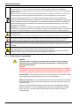
2.1.2 Precautionary labels
Read all labels and tags attached to the instrument. Personal injury or damage to the
instrument could occur if not observed.
This is the safety alert symbol. Obey all safety messages that follow this symbol to avoid potential injury. If on the
instrument, refer to the instruction manual for operation or safety information.
Ceci est le symbole d'alerte de sécurité. Se conformer à tous les messages de sécurité qui suivent ce symbole afin
d'éviter des blessures potentielles. Si apposés sur l'instrument, se référer au manuel d'utilisation pour le
fonctionnement ou les informations de sécurité.
5
General information
Electrical equipment marked with this symbol may not be disposed of in European public disposal systems after
12 August of 2005. In conformity with European local and national regulations (EU Directive 2002/96/EC),
European electrical equipment users must now return old or end-of life equipment to the Producer for disposal at no
charge to the user.
Note: For return for recycling, please contact the equipment producer or supplier for instructions on how to return
end-of-life equipment, producer-supplied electrical accessories, and all auxiliary items for proper disposal.
L'équipement électrique marqué de ce symbole ne devra pas être détruit dans les systèmes de
destruction publics Européens après le 12 août 2005. En conformité avec les dispositions européennes
locales et nationales (Directive EU 2002/96/EC), les utilisateurs européens d'équipements électriques
doivent maintenant renvoyer au fabricant pour destruction les équipements anciens ou en fin de vie,
sans frais pour l'utilisateur.
Remarque : Pour le retour à des fins de recyclage, veuillez contacter le fabricant ou le fournisseur
d'équipement pour obtenir les instructions sur la façon de renvoyer l'équipement usagé, les accessoires
électriques fournis par le fabricant, et tous les articles auxiliaires pour une mise au rebut appropriée.
This symbol, when noted on a product enclosure or barrier, indicates that a risk of electrical shock and/or
electrocution exists.
Si ce symbole ce trouve sur l’instrument, il indique la présence d’un danger de choc électrique ou d’électrocution.
This symbol, when noted on the product, identifies the location of the connection for Protective Earth (ground).
Ce symbole, lorsqu’il est apposé sur le produit, indique l’emplacement de la connexion de mise à la terre.
This symbol, when noted on the product, identifies the location of a fuse or current limiting device.
Lorsque ce symbole se trouve sur un produit, il indique l’emplacement d’un fusible ou autre protection contre les
surcharges.
This symbol, when noted on the product, indicated the presence of devices sensitive to Electro-static Discharge
(ESD) and indicated that care must be taken to prevent damage with the equipment.
Ce symbole, s'il figure sur le produit, indiqué la présence des dispositifs sensibles à la décharge électrostatique
(ESD) et la nécessité d'agir avec précaution pour éviter d'endommager l'équipement.
2.1.3 Confined space precautions
DANGER
Explosion hazard. Training in pre-entry testing, ventilation, entry procedures,
evacuation/rescue procedures and safety work practices is necessary before
entering confined spaces.
DANGER
Danger d'explosion. Une formation incluant des tests de pré-entrée, la ventilation,
les procédures d'entrée, les procédures d'évacuation/de sauvetage et des pratiques
de travail de sécurité est nécessaire avant d'entrer dans des espaces restreint.
Important Note: The following information is provided to guide users of Flo-Dar Sensors
on the dangers and risks associated with entry into confined spaces.
Remarque importante : Les informations suivantes sont fournies dans le but d'informer
les utilisateurs des capteurs Flo-Dar des dangers et des risques associés à l'accès aux
espaces confinés.
On April 15, 1993, OSHA’s final ruling on CFR 1910.146, Permit Required Confined
Spaces, became law. This new standard directly affects more than 250,000 industrial
sites in the U.S.A., and was created to protect the health and safety of workers in
confined spaces.
6
General information
Definition of a confined space:
A confined space is any location or enclosure that presents or has the immediate
potential to present one or more of the following conditions:
•
An atmosphere with less than 19.5% or greater than 23.5% oxygen and/or more than
10 ppm Hydrogen Sulfide (H2S).
•
An atmosphere that may be flammable or explosive due to gases, vapors, mists, dusts
or fibers.
•
Toxic materials which upon contact or inhalation, could result in injury, impairment of
health or death.
Confined spaces are not designed for human occupancy. They have restricted entry and
contain known or potential hazards. Examples of confined spaces include manholes,
stacks, pipes, vats, switch vaults, and other similar locations.
Standard safety procedures must always be followed prior to entry into confined spaces
and/or locations where hazardous gases, vapors, mists, dusts or fibers may be present.
Before entering any confined space check with your employer for procedures related to
confined space entry.
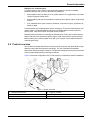
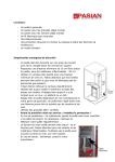
2.2 Product overview
The Flo-Dar Intrinsically Safe Sensor measures the flow velocity and liquid depth in open
channels using radar and ultrasonic technology. The unit is designed to withstand
submersion during surcharge conditions. The optional surcharge velocity sensor provides
velocity measurements during surcharge conditions.
Figure 1 shows the configuration of a Flo-Dar system in a hazardous location installation.
Figure 1 System overview
1
Hazardous environment
4
Logger or controller
2
Non-hazardous environment
5
Mounting frame
3
Intrinsically safe barrier
6
Flo-Dar sensor with optional surcharge velocity sensor
7
General information
8
Section 3
Installation
DANGER
Explosion hazard. Trained personnel only must install or commission the
equipment.
DANGER
Danger d'explosion. Seul le personnel formé est autorisé à installer ou à mettre en
service l'équipement.
This chapter includes only the installation information for hazardous location use. For the
installation, operation, and replacement part and accessory information for
non-hazardous location use, refer to the Flo-Dar Sensor User Manual.
3.1 Precautions for hazardous location installations
DANGER
Explosion hazard. To ensure safety, the installation of instruments in hazardous
locations must follow the specifications in the control drawings. Any modification
to the instrumentation or to the installation may result in life threatening injury
and/or damage to facilities.
DANGER
Danger d'explosion. Pour assurer la sécurité, l'installation des instruments dans
des emplacements dangereux doivent suivre les spécifications dans l'emplacement
dangereux indiqué sur la fiche technique. Toute modification de l'appareil ou de
l'installation peut conduire à des préjudices constituant un danger de mort et/ou
des dégâts sur les installations.
The Flo-Dar Intrinsically Safe Sensor is listed as intrinsically safe for Class 1, Zone 1,
Group IIB Hazardous Locations. This means that the circuits within these sensors cannot
produce a spark or thermal effect that could ignite a mixture of flammable or combustible
gases when installed properly. It does not mean that these sensors are explosion proof. If
proper safety precautions are not followed, or if the equipment is not installed properly,
there is a serious potential for explosion. Be sure to review all safety precautions,
installation and wiring practices throughout this manual before installing the Flo-Dar
Intrinsically Safe Sensor.
3.1.1 Intrinsically safe installation requirements
Installation of this equipment must satisfy local electrical code requirements using the
hazardous location control drawings and is subject to final approval by the authority
having jurisdiction. Install all associated apparatus, such as the intrinsically-safe barrier,
logger or controller in a non-hazardous location.
3.1.2 Hazardous location control drawings
DANGER
Explosion hazard. Never connect items to the sensor that are not specified on the
control drawings. Do not connect or disconnect any equipment unless power has
been switched off or the area is known to be non-hazardous.
DANGER
Danger d'explosion. Ne branchez jamais au transmetteur des éléments ne figurant
pas sur la fiche technique. Ne branchez et ne débranchez aucun équipement sans
avoir préalablement coupé l'alimentation et vous être assuré que l'environnement
ne présentait aucun danger.
Follow the control drawings provided (section 3.4 on page 15) and all codes and
regulations for connection to the sensor in the hazardous location.
9
Installation
3.2 Sensor installation
WARNING
Explosion hazard. Installation of equipment into hazardous locations must be done
so that no friction can be generated between the Flow Meter and any surrounding
surfaces.
AVERTISSEMENT
Risque d'explosion. L'installation de l'équipement dans des zones dangereuses
doit être effectuée de sorte qu'aucun frottement ne soit provoqué entre le
débitmètre et toute surface environnante.
Mount the Flo-Dar sensor above the open channel on the wall of the manhole. For
hazardous locations, a barrier must be installed outside of the hazardous area.
To prevent damage to the enclosure, do not mount the Flo-Dar sensor in a location that
receives direct sunlight.
3.2.1 Install the frame on the wall
DANGER
Explosion hazard. Review the safety information in section 2.1 on page 5 and
section 3.1 on page 9 before entering a confined space.
DANGER
Danger d'explosion. Revoyez les information concernant la sécurité dans
section 2.1 on page 5 et section 3.1 on page 9 avant d'entrer dans une espace
restreint.
3.3 Electrical installation
3.3.1 Wiring safety information
CAUTION
Always disconnect power to the instrument when making any electrical
connections.
ATTENTION
Débranchez toujours l'alimentation de l'appareil avant toute connexion électrique.
WARNING
Explosion hazard. Voltage connections to the barrier must be from 12 VDC
powered loggers. Power can be supplied from a battery or 12 VDC SELV source
which has 3rd party NRTL certifications for Canada and the U.S.A., and the correct
CE marking and Declaration of Conformity for Europe.
AVERTISSEMENT
Risque d'explosion. La connections électrique sur le système de barrière de
sécurité est seulement possible avec des appareils alimentés en 12VDC.
L'alimentation peut venir d'une batterie ou d'une source 12VDC séparée ou très
basse tension sécurisée (SELV) qui possède la 3ème partie de certifications NRTL
pour le CANADA et USA, et le marquage CE et déclaration de conformité pour
l'Europe.
10
Installation
3.3.2 Electrical installation in a hazardous location
A barrier with appropriate entity parameters must be installed between the sensor and the
logger or controller for installation in hazardous locations. If the SVS option is used, an
additional barrier with appropriate entity parameters must also be installed between the
SVS component and the logger or controller.
3.3.2.1 Install the barrier
A barrier must be installed when the Flo-Dar sensor is installed in a hazardous location
as defined in section 3.1 on page 9. A barrier limits the power parameters to the device
that is located in the hazardous area. The barrier and the logger or controller must always
be installed in a non-hazardous location.
The barrier has a dielectric strength of 500 Vrms between the intrinsically safe outputs
and the frame of the apparatus. Separation between the intrinsically safe outputs and
connections to non-intrinsically safe devices and separation between separate
intrinsically safe output channels (power, RS485A and RS485B) should be maintained in
accordance with the installation instructions and markings since there is no galvanic
isolation between these circuits.
Procedure
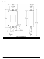
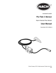
1. Install the barrier on a wall in a non-hazardous environment (Figure 2 on page 12).
2. Follow the control drawings provided (section 3.4 on page 15) and all codes and
regulations for connection to the sensor in the hazardous location.
11
Installation
Figure 2 Barrier dimensions
1
12
Desiccant
2
Connector for protective earth ground (PEG)
Installation
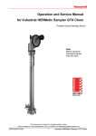
3.3.2.2 Wiring to the barrier
Use the supplied cables for electrical wiring to the barrier. Make sure to install a
protective earth ground to the barrier.
Procedure
1. Remove the four screws from the cover of the barrier. Remove the cover.
2. Insert the cable from the Flo-Dar sensor through the strain relief fitting on the side of
the barrier with the hazardous area connection label (Figure 3 on page 14). Tighten
the strain relief.
3. If the Flo-Dar sensor has the optional SVS component, insert the cable from the SVS
sensor through the strain relief fitting on the side of the second barrier with the
hazardous area connection label (Figure 3 on page 14). Tighten the strain relief.
4. Prepare each wire.
5. Install the wires in terminals J3 and J4 as shown in Figure 3 on page 14. Pull lightly
after each insertion to make sure the connections are tight.
6. Install the air tube from the sensor cable into the fitting in the barrier enclosure as
shown in Figure 3 on page 14.
WARNING
Explosion hazard. The air tube must stay attached to the fitting to make sure that
dust does not go into the enclosure if the fitting is damaged.
AVERTISSEMENT
Risque d'explosion. Le tube d'air doit rester fixé au raccord afin de s'assurer que de
la poussière ne pénètre pas dans le boîtier si le raccord est endommagé.
7. Insert the cable from the logger or controller through the strain relief fitting on the
other side of the barrier (Figure 3 on page 14). Tighten the strain relief.
8. Prepare each wire.
9. Install the wires in terminals J1 and J2 as shown in Figure 3 on page 14. Pull lightly
after each insertion to make sure the connections are tight.
10. Replace the cover on the barrier and install the screws.
11. Connect a protective earth ground (PEG) to the ground stud on the barrier (Figure 2
on page 12) where local code or authorities permit or require such a connection. If
required, use a copper wire that is AWG 9 or larger.
13
Installation
Figure 3 Barrier wiring
1
14
Cable to logger or controller
2
Cable from Flo-Dar or SVS sensor
Installation
3.3.2.3 Connection to the logger or controller
Important Note: The length of the cable between the barrier and the logger or controller
cannot be longer than 750 feet.
Remarque importante : La longueur du câble entre la plaque et l'enregistreur ou le
transmetteur ne doit pas dépasser les 229 mètres.
Connect the cable from the barrier to the logger or the controller:
•
Logger—connect the cable from the barrier to the connector on the logger. Make
sure that the barrier that is connected to the Flo-Dar sensor is connected to the
Flo-Dar connector on the logger. Make sure that the barrier that is connected to
the optional SVS sensor is connected to the SVS connector on the logger.
•
Controller—connect the cable from the barrier to the controller. For wire terminal
connections to the controller, refer to the user manual for the controller. Make sure
that the barrier that is connected to the Flo-Dar sensor is connected to the Flo-Dar
terminal in the controller. Make sure that the barrier that is connected to the
optional SVS sensor is connected to the SVS terminal in the controller.
Figure 4 Typical intrinsically safe configuration
1
Flo-Dar sensor
4
Barrier
2
Intrinsically-safe environment
5
750 ft maximum cable length between barrier and logger
or controller
3
Non-intrinsically-safe environment
6
Logger or controller
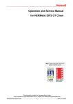
3.4 Approved Flo-Dar installation drawings
DANGER
Any installation or flow meter configuration that is not specifically detailed on the
following control drawings is not allowed. In all cases, the local authority having
jurisdiction shall have the final say.
DANGER
Il est interdit de procéder à toute installation ou configuration d'un débitmètre qui
n'est pas explicitement détaillée dans les schémas de contrôle de l'installation
ci-dessous. Dans tous les cas, c'est l'autorité locale responsable qui aura le dernier
mot.
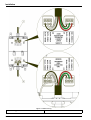
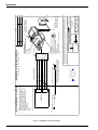
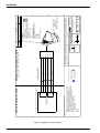
Figure 5 on page 16, Figure 6 on page 17 and Figure 7 on page 18 are approved control
drawings. These certified drawings explain the ONLY approved method of installing the
Flo-Dar sensor. Additionally, these drawings list both part number, description, and the
only certified sensors, probes, and associated equipment to be used with this sensor. Any
substitutions will automatically void the Intrinsically Safe certification of the flow meter
and could result in fire or explosion.
15
16
Figure 5 Installation Control Drawing 1
$
%
&
'
*5281',1*675$331
$662&,$7('
$33$5$786
-3,1
-3,1
-3,1
-3,1
-3,1
-3,1
$662&,$7('$33$5$7866+2:15()(5(1&(21/<
127(6
:,5,1*0(7+2'60867%(,1$&&25'$1&(:,7+
(/(&75,&$/&2'(5(48,5(0(1762)&28175<2)
(1'86(%$6('21=21(&/$66,),&$7,21
/L&L 8L(17,7<3$5$0(7(56$33/<(48$//<72
$//7+5((&+$11(/6,L$1'3L(17,7<
3$5$0(7(56$5(727$/287387)25$//7+5((
&+$11(/6 32:(556$ 56% /L/FDEOH/R
&L&FDEOH&R
3L3R
,L,R
8L8R
121+$=$5'286/2&$7,21
:+,7(
%/$&.
5('
*5((1
&$%/(31
0$;/(1*7+)7 P
7+,6'5$:,1*
35,2572&+$1*,1*
$33529$/5(48,5('
5(*8/$725<$*(1&<
&,5&8/$5
&211(&725
5$7,1*6
&RQIRUPVWR$16,8/DQG
$16,8/
&HUWLILHGWR&$1&6$&1R
DQG&$1&6$(
&ODVV,=RQH$([LE,,%7
([LE,,%7
&7DPE &
3ROOXWLRQGHJUHH2YHUYROWDJH&DWHJRU\,
,3
'$7$6+,(/'
56$
56%
9LQ
WJULVVHQ
237,21$/
/21*5$1*(6(1625
&$%/(31
0$;/(1*7+)7 P
,6'(9,&( )/2'$5
$66(0%/<31;;
:+(5(;; 7+58
$33529('
'(6&5,37,21
%
5(9,6,21
5(9
0$7(5,$/
'21276&$/('5$:,1*
,17(535(7*(20(75,&
72/(5$1&,1*3(5
$16,<0
',0(16,216$5(,1,1&+(6
72/(5$1&(6
; ;; ;;; $1*/(6 81/(6627+(5:,6(63(&,),('
+$&+&203$1<
&21752/'5$:,1*
,6)/2'$5
6&$/( :(,*+7
6+((72)
% )/2'$59 %
5(9
/,1'%(5*+'5
/29(/$1'&2
6,=( ':*12
7+,5'$1*/(352-(&7,21 7,7/(
(1*,1((5
'$7(
5/87+(5 5/87+(5 '5$:1
1$0(
127,&(+$&+&203$1<&/$,0635235,(7$5<5,*+76,17+(,1)250$7,21',6&/26('217+,6'5$:,1*,7,6,668('
,1&21),'(1&()25(1*,1((5,1*,1)250$7,2121/<$1'0$<127,1:+2/(25,13$57%(86('720$1)$&785(
$1<7+,1*:+(7+(5251276+2:1+(5(215(352'8&('25',6&/26('72$1<21(:,7+287',5(&73(50,66,21
)520+$&+&203$1<
:$51,1*86(*5281'('5(75,(9$/32/(72
35(9(1767$7,&',6&+$5*(:+(15(029,1*
,6'(9,&()520+$=$5'286/2&$7,21
&$%/(6+,(/'
9LQ
(17,7<3$5$0(7(56
$//&+$11(/66((127( /L X+
&L X)
3L :
8L 9'&
,L $
&ODVV,=RQHRU*URXS,,$RU,,%7
+$=$5'286 &/$66,),(' /2&$7,21
5(75,(9$/32/(31
$
%
&
'
Installation
$
%
&
'
(
)
/2**(5
6((127(
,6%$55,(5
$66(0%/<31
121+$=$5'286/2&$7,21
/R/L/FDEOH/FDEOH X+)250$;&$%/(/(1*7+2))7
&R&L&FDEOH&FDEOH X))250$;&$%/(/(1*7+2))7
/R&R 8R(17,7<3$5$0(7(56$33/<(48$//<72$//7+5((&+$11(/6,R$1'3R
(17,7<3$5$0(7(56$5(727$/287387)25$//7+5((&+$11(/6 32:(556$ 56% 21(%$55,(53(5,6'(9,&(
%$55,(5*5281'6+$//%(&211(&7('3(5&2'(5(48,5(0(176,1&28175<2)
(1'86(
$33529$/5(48,5('
/2**,1*(48,30(17&211(&7('72%$55,(5086712786(25*(1(5$7(025(
7+$19'& 8P 9'& 7+,6'5$:,1*
35,2572&+$1*,1*
5(*8/$725<$*(1&<
237,21$/32:(56285&(0867%(6(/95$7('$1'2873879'&
25$1*(
:+,7(
%/$&.
5('
*5((1
9
56$
56%
9LQ
9LQ
&$%/(6+,(/'
'$7$6+,(/'
56$
56%
9LQ
9LQ
&$%/(6+,(/'
'(6&5,37,21
5(9,6,21
352'8&7,215(/($6(
,6'(9,&(:,7+121'(7$&+$%/(&$%/(
$33529('
,6'(9,&(:,7+'(7$&+$%/(&$%/(
&,5&8/$5
&211(&725
$
5(9
0$7(5,$/
'21276&$/('5$:,1*
,17(535(7*(20(75,&
72/(5$1&,1*3(5
$16,<0
',0(16,216$5(,1,1&+(6
72/(5$1&(6
; ;; ;;; $1*/(6 81/(6627+(5:,6(63(&,),('
1$0(
'$7(
5/87+(5 5/87+(5
+$&+&203$1<
,6%$55,(5
&21752/'5$:,1*
6&$/( :(,*+7
6+((72)
& %$55,(59 $
5(9
/,1'%(5*+'5
/29(/$1'&2
6,=( ':*12
7+,5'$1*/(352-(&7,21 7,7/(
(1*,1((5
'5$:1
127,&(+$&+&203$1<&/$,0635235,(7$5<5,*+76,17+(,1)250$7,21',6&/26('217+,6'5$:,1*,7,6,668('
,1&21),'(1&()25(1*,1((5,1*,1)250$7,2121/<$1'0$<127,1:+2/(25,13$57%(86('720$1)$&785(
$1<7+,1*:+(7+(5251276+2:1+(5(215(352'8&('25',6&/26('72$1<21(:,7+287',5(&73(50,66,21
)520+$&+&203$1<
0$;/(1*7+)7 P
25
:+,7(
%/$&.
5('
*5((1
&$%/(31
0$;/(1*7+)7 P
-3,1
-3,1
-3,1
-3,1
-3,1
-3,1
-3,1
-3,1
-3,1
-3,1
-3,1
-3,1
&ODVV,=RQHRU*URXS,,$RU,,%7
+$=$5'286 &/$66,),(' /2&$7,21
*5281'
/8*
*5281'
/8*
:,5,1*0(7+2'60867%(,1$&&25'$1&(:,7+(/(&75,&$/&2'(5(48,5(0(176
2)&28175<2)(1'86(%$6('21=21(&/$66,),&$7,21
,6%$55,(5
$66(0%/<31
/2**(5
6((127(
127(6
237,21$/32:(5
6285&(
6((127(
(17,7<3$5$0(7(56
$//&+$11(/66((127( /RX+ 6((127(
&RX) 6((127(
8R 9'&
3R :
8P 9'&
,R $
/R5R X+2KP
5$7,1*6
&RQIRUPVWR$16,8/DQG
$16,8/
&HUWLILHGWR&$1&6$&1R
DQG&$1&6$( &ODVV,=RQH>$([LE*E@,,%
>([LE*E@,,%
&7DPE &
3ROOXWLRQ'HJUHH2YHUYROWDJH&DWHJRU\,
,3
237,21$/32:(5
6285&(
6((127(
$
%
&
'
(
)
Installation
Figure 6 Installation Control Drawing 2
17
18
Figure 7 Installation Control Drawing 3
$
%
&
'
-3,1
-3,1
-3,1
127(6
:,5,1*0(7+2'60867%(,1$&&25'$1&(:,7+
(/(&75,&$/&2'(5(48,5(0(1762)&28175<2)
(1'86(%$6('21=21(&/$66,),&$7,21
/L&L 8L(17,7<3$5$0(7(56$33/<(48$//<72
$//7+5((&+$11(/6,L$1'3L(17,7<3$5$0(7(56
$5(727$/,1387)25$//7+5((&+$11(/6
32:(556$ 56% /L/FDEOH/R25/L5L/R5R
&L&FDEOH&R
3L3R
,L,R
8L8R
$662&,$7('
$33$5$786
-3,1
-3,1
-3,1
$662&,$7('$33$5$7866+2:15()(5(1&(21/<
121+$=$5'286/2&$7,21
7+,6'5$:,1*
35,2572&+$1*,1*
$33529$/5(48,5('
5(*8/$725<$*(1&<
25$1*(
:+,7(
%/$&.
5('
*5((1
&$%/(31
0$;/(1*7+)7 P
,6'(9,&( 696
$66(0%/<31
;;
:+(5(;; 25
(17,7<3$5$0(7(56
$//&+$11(/66((127( /L X+
&L X)
3L :
8L 9'&
,L $
/L5L X+2KP
5$7,1*6
&RQIRUPVWR$16,8/DQG
$16,8/
&HUWLILHGWR&$1&6$&1R
DQG&$1&6$(
&ODVV,=RQH$([LE,,%7*E
([LE,,%7*E
&7DPE &
,3
$33529('
'(6&5,37,21
352'8&7,215(/($6(
$
5(9,6,21
5(9
0$7(5,$/
'21276&$/('5$:,1*
,17(535(7*(20(75,&
72/(5$1&,1*3(5
$16,<0
',0(16,216$5(,1,1&+(6
72/(5$1&(6
; ;; ;;; $1*/(6 81/(6627+(5:,6(63(&,),('
1$0(
'$7(
5/87+(5 5/87+(5 +$&+&203$1<
6&$/( :(,*+7
6969
$
5(9
6+((72)
&21752/'5$:,1*
,6696
/,1'%(5*+'5
/29(/$1'&2
6,=( ':*12
%
7+,5'$1*/(352-(&7,21 7,7/(
(1*,1((5
'5$:1
127,&(+$&+&203$1<&/$,0635235,(7$5<5,*+76,17+(,1)250$7,21',6&/26('217+,6'5$:,1*,7,6,668('
,1&21),'(1&()25(1*,1((5,1*,1)250$7,2121/<$1'0$<127,1:+2/(25,13$57%(86('720$1)$&785(
$1<7+,1*:+(7+(5251276+2:1+(5(215(352'8&('25',6&/26('72$1<21(:,7+287',5(&73(50,66,21
)520+$&+&203$1<
9
56$
56%
9LQ
9LQ
&$%/(6+,(/'
&ODVV,=RQHRU*URXS,,$RU,,%7
+$=$5'286 &/$66,),(' /2&$7,21
$
%
&
'
Installation
Section 4
Maintenance
DANGER
Explosion hazard. Only qualified personnel should conduct the tasks described in
this section of the manual.
DANGER
Danger d'explosion. Les opérations décrites dans cette section du manuel ne
doivent être effectuées que par du personnel qualifié.
DANGER
Explosion hazard. When using the retrieval pole, make sure to connect the
grounding strap to the ground lug on the barrier. The sensor must also be
connected to the barrier during maintenance activities. This is to prevent ignition
of explosive gases due to static discharge.
DANGER
Danger d'explosion. Lors de l'utilisation du pôle de récupération, assurez-vous de
connecter la languette de mise à la masse à la cosse de masse de la plaque. Le
capteur doit également être connecté à la plaque pendant les opérations de
maintenance. Ceci sert à éviter d'enflammer les gaz explosifs dus à la décharge
statique.
The safety provided by the barrier may be impaired if any of the following
conditions have occurred:
•
visible damage
•
storage above 70 ºC for prolonged periods
•
exposure to severe transport stresses
•
previous installation
•
failure to operate properly
If any of these conditions have occurred, return the device to the manufacturer for
recertification.
WARNING
Explosion hazard. To prevent ignition of explosive atmospheres, disconnect power
before servicing.
AVERTISSEMENT
Risque d'explosion. Pour éviter tout risque de déflagration, mettez l’appareil hors
tension avant toute intervention d’entretien.
This chapter includes only the maintenance information for hazardous location use. For
the maintenance information for non-hazardous location use, refer to the Flo-Dar Sensor
User Manual.
The Flo-Dar sensor contains no user serviceable or repairable components. If service is
necessary, the Flo-Dar sensor must be sent to an authorized service center for repair or
servicing.
19
Maintenance
4.1 Cleaning the instrument
DANGER
Explosion hazard. Never attempt to wipe or clean the Flo-Dar or SVS sensor while
in a hazardous location. Do not use abrasives or high-pressure hoses or washers
to clean the sensors. Do not disturb the pressure port on the bottom of the sensor.
DANGER
Danger d'explosion. N'essayez jamais d'essuyer ou de nettoyer le Flo-Dar ou le
capteur SVS dans un emplacement dangereux. N'utilisez pas de produits abrasifs
ou de tuyaux sous pression ou d'appareils de nettoyage pour nettoyer les capteurs.
Ne dérangez pas le port sous pression situé dans le bas du capteur.
20
U.S. and countries other than EU
HACH COMPANY
4539 Metropolitan Court
Frederick, MD, 21704-9452, U.S.A.
Tel. (800) 368-2723
Fax (301) 874-8459
[email protected]
www.hachflow.com
Marsh-McBirney and Sigma Flow
Products (except Sigma Flow
Products in France and the UK)
FLOWTRONIC, SA.
Rue J.H. Cool 19a
B-4840 Welkenraedt, Belgium
Tel. +32 (0) 87 899 799
Fax +32 (0) 87 899 790
www.flow-tronic.com
France and UK
(Sigma Flow Products Only)
HACH LANGE GmbH
Willstätterstraße 11
D-40549 Düsseldorf, Germany
Tel. +49 (0) 211 5288-0
Fax +49 (0) 211 5288-143
E-mail: [email protected]
www.hach-lange.com
© Hach Company/Hach Lange GmbH, 2010, 2011. All rights reserved. Printed in U.S.A.