1
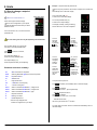
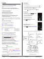
RWF40 Hints Manual This RWF40 Hints Manual is intended for use by OEMs which integrate the controller into their products! CC1B-Hints-en Preliminary 04.02.2003 Siemens Building Technologies HVAC Products This page is intentionally left blank… 2/16 CC1B-Hints-en Preliminary 04.02.2003 HVAC Products Contents 1. Introduction to hints manual.........................................................................................3 1.1.1 How to use this manual ....................................................................................................................................................................3 1.1.2 Symbols used in this manual ............................................................................................................................................................3 2. Hints. ................................................................................................................................4 2.1 Getting started with the RWF40 menu . ........................................................................................................4 2.1.1 Start with the Basic Display . ............................................................................................................................................................4 2.1.2 User level .........................................................................................................................................................................................4 2.1.3 Parameter level . ...............................................................................................................................................................................4 2.1.1 Configuration level . ..........................................................................................................................................................................4 2.2 How to configure your RWF40 . ....................................................................................................................5 2.3 How to adjust parameters . ...........................................................................................................................6 2.4 How to change a setpoint (SP1, SP2, or dSP) ..............................................................................................7 2.5 How to display the software version and units . .............................................................................................8 2.6 Manual operation . ........................................................................................................................................9 2.7 Auto Tune (self setting function ..................................................................................................................10 2.8 Setting up a standard temperature application . ..........................................................................................11 2.9 Setting up a standard pressure application .................................................................................................12 2.10 How to unlock an RWF40 controller . ..........................................................................................................13 3. Notes. .............................................................................................................................14 3.1 Logic summary ..........................................................................................................................................14 3.2 List of values for User settings, Parameters, and Configurations . ...............................................................15 1. Introduction to hints manual 1.1.1 How to use this manual This RWF40 hint manual is intended to supplement the RWF40 User Manual. Please read the RFW40 User Manual before applying power to the controller. 1.1.2 Symbols used in this manual These symbols represent the four buttons on the controller. If a combination of keys is required an explanation will be given. This symbol is used to draw your attention to a particular remark. This symbol indicates a refererence to the RWF40 user manual. 3/16 CC1B-Hints-en Preliminary 04.02.2003 HVAC Products 2.1.3 Parameter Level 2. Hints 2.1 Getting started with the RWF40 menu The RWF40 menu system has three Levels, beyond the Basic Display, the User Level, the Parameter Level and the Configuration Level. RWF40 user manual Section 6 Operation. 2.1.1 Start with the Basic Display Shown at the right is the basic display. The upper, larger, 4 digit red LEDs, (180) will be referred to as, the ‘Actual value display’. The lower, smaller, 4 digit green LEDs, (180) will be referred to as, the ‘Setpoint display’. The current configuration of your specific controller will determine which levels you will be allowed to access. C112 must be xxx0 to access the configuration level. The C112 locking code can only be adjusted by the manufacturer. From the user level you may advance to the parameter level, and holding, for 3 seconds, by pressing and then releasing it. C112 must be xxx0 or xxx1, to access this level. The actual value display, (0) shows the parameter ’s actual value. The setpoint display, (AL) shows the parameter you are adjusting or viewing. You can adjust the values for AL, Hyst, Pb.1, dt, rt, HYS.1, HYS.2, HYS.3, q, H, and P, depending on your specific configuration. To adjust parameter values, please see “3 How to adjust parameters “, or RWF40 user manual Section 7. 2.1.4 Configuration Level From the parameter level you may advance to the configuration level, and holding, again for 3 seconds, by pressing and then releasing it. All controllers will return to the basic display automatically, if no key is pressed for 30 seconds. The RWF40 configuration codes (C111, C112, and C113) are all four digits. The x’s used in the explanations in this manual represent a ‘don’t care’ digit in the code, so, xxx0 could mean 1000, 2100, 5430, etc, and we are only concerned with the ‘non-x’ digits. C112 code summary : C112 code C112 code C112 code C112 code xxx0 xxx1 xxx2 xxx3 Locks nothing Locks the Configuration Level Locks the Parameter Level Locks all levels and keys C112 must be xxx0 to access this level. The actual value display, (9030) shows the configuration item’s actual value. The setpoint display, (C111) shows the configuration item you are adjusting. You can adjust the values, within limits, for C111, C112, C113, SCL, SCH, SCL2, SCH2, SPL, SPH, OFF1, OFF2, OFF3, and dF1 depending on your specific configuration. To adjust configuration values, please see the “2 How to configure our RWF40 “, or RWF40 user manual Section 8. 2.1.2 User Level Return to the Basic Display From the basic display, you may advance to the user level, by pressing and releasing it. You may exit any level, and return to the basic display at any time, in two ways. The actual value display, (180) shows the setpoint you are adjusting or viewing. First, to exit immediately, press The setpoint display, (SP 1) shows the parameter you are adjusting or viewing. and release it. The second way is to simply wait 30 seconds, and the controller will automatically return to the basic display. You can adjust the values, within limits, for SP1, SP2, dSP, view tA, SP.E, depending on your specific configuration. To adjust user level values, please see the “4 How to change a setpoint “, or RWF40 user manual Section 6.2.1. 2/16 CC1B-Hints-en Preliminary 04.02.2003 HVAC Products Example 2. Hints 2.2 How to configure your RWF40 Re-configure (adjust) the value for C111 If no keys are pressed for 30 seconds, at anytime, the controller will automatically return to the basic display. Shown at the right is the basic display. The current value of C111, (9030) is shown in the actual value display. The current configuration of your specific controller will determine which levels you will be allowed to access. The current configuration item (C111) is shown in the setpoint display. C112 must be xxx0 to access the configuration level. The C112 locking code can only be adjusted by the manufacturer. The display is steady, (not flashing) and by default, th the 4 , (rightmost) digit is the one you may now adjust. You can select the digit you want to adjust, by pressing once and releasing it. rd To reach the configuration level, you start from the basic display, (shown above), skip past the user level, and go first, to the parameter level, and then, finally, to the configuration level. Press The 3 digit is now flashing, indicating that it is now, the adjustable digit. (Each time you press and release you cycle, thru each digit, right-to-left and back again) and hold for 3 seconds, and then release it. You are now at the parameter level. To change the value of the flashing digit, press and release it. From the parameter level you may now advance to the configuration level, Each time you press and release, you cycle up thru the allowable values, and back again. by pressing again, holding, for 3 seconds, and then releasing it. The actual value display, (9030) shows the current configuration value. The setpoint display, (C111) shows the configuration item you are adjusting. Configuration level items summary : C111 C112 C113 Analog input 1 Analog input 2 Analog input 3 D2 function sensors (14 types), standard signal none, external SP, analog SP Shift none, outdoor sensors … none, SP chg/over, SP binary shift Limit comparator Controller type Setpoint SP1 Locking none, input 1,2,3 … 3-position, modulating 0-20mA, … via buttons, with outside sensor none, configuration, parameters, buttons Unit address Unit address Decimal - Units Signal out-of-range 0-9 0-9 º C or º F and decimals limit comparator OFF/ON SCL SCH SCale Low Analog input 1 SCale High Analog input 1 SCL2 SCH SCale Low Analog input 2 SCale High Analog input 2 SPL SPH Set Point, Lower Set Point, Higher OFF1 OFF2 OFF2 Actual value correction, OFFset, Analog input 1 Actual value correction, OFFset, Analog input 2 Actual value correction, OFFset, Analog input 3 Df1 Digital filter time constant for Analog input 1 3/16 Once you have the desired value displayed and flashing, you may accept it by pressing and releasing it. once All four upper digits will flash once. The controller displays the new configuration values, in 4 steady digits. Your options at this point are: Press or and release, to immediately return to the basic display. press and release it, to advance to C112, press again and release it, to advance to C113, press and release it, to advance to SCL, … after the last configuration item Df1, press st and release it, to advance to AL, (the 1 parameter), … after the last parameter item P, press CC1B-Hints-en Preliminary st and release it, to advance to SP1, (the 1 user item), st … after the last user item it cycles back to the 1 user item. Or simply wait 30 seconds and the controller will automatically return to the basic display. 04.02.2003 HVAC Products Example 2. Hints Adjust the value for parameter AL. 2.3 How to adjust parameters RWF40 user manual Section 6.3 If no keys are pressed for 30 seconds, at anytime, the controller will automatically return to the basic display. Shown at the right is the basic display. The current value of AL, (0) is shown in the actual value display. The current configuration of your specific controller will determine which levels you will be allowed to access. The current parameter item (AL) is shown in the setpoint display. C112 must be xxx1 or xxx0 to access the parameter level. The display is steady, (nothing is flashing) and the value for AL can now be adjusted. The C112 locking code can only be adjusted by the manufacturer. From the basic display, you may skip the user level, to reach the parameter level. Press and hold, for 3 seconds, and release. You can decrease the value by pressing and releasing it. You can increase the value by pressing and releasing it. You can accept the change by waiting 2 seconds. Or, you can advance to the Next parameter by pressing The actual value display, (0) shows the current parameter value. The setpoint display, (AL) shows the parameter item you are adjusting. Parameter level items summary: AL Alarm Limit value for comparator HYSt Switching differential, Hysteresis for limit comparator Pb.1 Proportional band 1 dt derivative time rt Integral action time db * dead band, contact spacing tt * Actuator running time HYS1 Switch-on threshold, Hysteresis 1, 2-stage burner HYS2 Switch-off threshold, Hysteresis 2, 2-stage burner HYS3 Switch-off threshold, Hysteresis 3, upper q Response threshold H Heating curve slope P Parallel displacement * Items are only displayed when controller is configured for a 3-position output. The red LED’s will blink once, and become the new value. once and releasing it. HYSt can be adjusted the same way you just did AL. Your options at this point are: Press and release, to immediately return to the basic display. and release it, to advance down to Pb.1, Press (the next parameter). … after the last parameter item P, press and release it, st to advance down to SP1, (the 1 user item). st … after the last user item, the menu cycles back to the 1 user item. Or simply wait 30 seconds and the controller will automatically return to the basic display. 4/16 CC1B-Hints-en Preliminary 04.02.2003 HVAC Products Example 2. Hints 2.4 How to change a setpoint Adjust the value for parameter AL. If no keys are pressed for 30 seconds, at anytime, the controller will automatically return to the basic display. (SP1, SP2, or dSP) RWF40 user manual Section 6.2 The current value of AL, (0) is shown in the actual value display. Shown at the right is the basic display. The current parameter item (AL) is shown in the setpoint display. The current configuration of your specific controller will determine which levels you will be allowed to access. The display is steady, (nothing is flashing) and the value for AL can now be adjusted. C112 must be xxx2, xxx1, or xxx0 to access the parameter level. The C112 locking code can only be adjusted by the manufacturer. From the basic display, you may skip the user level, to reach the parameter level. You can decrease the value by pressing and releasing it. You can increase the value by pressing and releasing it. You can accept the change by waiting 2 seconds. Or, you can advance to the next parameter by pressing Press and hold, for 3 seconds, and release. The actual value display, (0) shows the current parameter value. The setpoint display, (AL) shows the parameter item you are adjusting. Parameter level items summary: AL Alarm Limit value for comparator HYSt Switching differential, Hysteresis for limit comparator Pb.1 Proportional band 1 dt derivative time rt Integral action time db * dead band, contact spacing tt * Actuator running time HYS1 Switch-on threshold, HYSteresis 1, 2-stage burner HYS2 Switch-off threshold, HYSteresis 2, 2-stage burner HYS3 Switch-off threshold, HYSteresis 3, upper q Response threshold H Heating curve slope P Parallel displacement The red LED’s will blink once, and become the new value. once and releasing it. HYSt can be adjusted the same way you just did AL Your options at this point are: * items are only displayed when controller is configured for 3-pos output. Press and release, to immediately return to the basic display. and release it, Press to advance down to Pb.1, (the next parameter). … after the last parameter item P, press and release it, st to advance down to SP1, (the 1 user item). … after the last user item, st the menu cycles back to the 1 user item. Or simply wait 30 seconds and the controller will automatically return to the basic display. 5/16 CC1B-Hints-en Preliminary 04.02.2003 HVAC Products 2. Hints 2.5 How to display the software version and units RWF40 user manual Section 6.2 .5 Shown at the right is the basic display. The current configuration of your specific controller will determine which levels you will be allowed to access. 2.6 Manual operation A C112 of xxx3 will prevent use of the keys. RWF40 user manual Section 6.2 .2 and 6.2.3. The C112 locking code can only be adjusted by the manufacturer. Shown at the right is the basic display. You can display the software version, and units, of your controller,at any time, by pressing the at the same time,and holding them… You will see one, of the three displays shown below. The current configuration of your specific controller will determine which levels you will be allowed to access. A C112 of xxx3 will prevent use of the keys. The C112 locking code can only be adjusted by the manufacturer. The software version of your controller, (Version 102 in this example.) is shown in the actual value display. The current units configuration ( ºC, ºF, or %) is shown in the setpoint display. The display will return, to the where it was, if you release the keys at the same time, if not, you will return back to the basic display. Manual operation can only be performed when the thermostat function is active and burner is released to modulation. The green burner LED must be on, relay 1 is energized, and the contact, Q13 N.O. - Q14 Com, is closed. If at any time the burner LED turns off, the controller will exit the manual operation function. Configure Codes \ Units summary: ºC will be displayed if your controller is configured with: C111 C113 C113 0xxx .. dxxx xx0x xx1x Analog input 1 No decimals One decimal Sensor (Pt100, Ni100, .. ) ºC ºC ºF will be displayed if your controller is configured with C111 0xxx .. dxxx Analog input 1 Sensor (Pt100, Ni100, .. ) C113 xx2x No decimals ºF C113 xx3x One decimal ºF % w ill be displayed if your controller is configured with: C111 Exxx .. Hxxx Analog input 1 Standard input (4-20mA, .. ) C113 xx0x .. xx3x Doesn’t matter 6/16 CC1B-Hints-en Preliminary 04.02.2003 HVAC Products 2. Hints 2.6 Manual operation continued… Modulating burner, 3-Position output Press and hold for 5 seconds, and release. Modulating burner, Modulating output Press and hold for 5 seconds, and release. The red LED above the manual icon turns on to indicate that the controller is now in the manual mode. The red LED above the manual icon turns on to indicate that the controller is now in the manual mode. Relay 2 and relay 3 will hold their current state, (energized or de-energized) that they were in until another key is pressed. Relay 2 and relay 3 will hold their current state, (energized or de-energized) that they were in until another key is pressed. By design, the 0 output starts driving the modulating device to low fire, but if you promptly press the after the red LED above the hand icon turns on, you can prevent the from going all the way. When the is pressed: -Relay 3 is energized -Decrease icon turns on -N.O. contact Q-Y2 closes, to drive the modulating device down, which decreases the firing rate of the burner. When the is released: -Relay 3 is de-energized -Decrease icon turns off -N.O. contact Q-Y2 opens, to hold the modulating device where it is, which holds the firing rate of the burner. When the is pressed, the output value starts increasing, and the output, to terminals X1+ and X1starts increasing, the same amount, and increases the firing rate of the burner. When the is released, output value, stops increasing, and the output, to terminals X1+ and X1- also stops increasing, and holds the current firing rate of the burner. When the is pressed: -Relay 2 is energized -Increase icon turns on -N.O. contact Q-Y1 closes, to drive the modulating device up, which increases the firing rate of the burner. When the is released: -Relay 2 is de-energized -Increase icon turns off -N.O. contact Q-Y1 opens, to hold the modulating device where it is, which holds the firing rate of the burner. When the is pressed, the output value starts decreasing, and the output, to terminals X1+ and X1starts decreasing, the same amount, and decreases the firing rate of the burner. When the is released, output value, stops decreasing, and the output, to terminals X1+ and X1- also stops decreasing, and holds the current firing rate of the burner. To exit manual operation Press for 5 seconds, and release. The red LED above the hand symbol turns off, and the controller returns to the automatic mode. On Modulating burners, with modulating output, the output to terminals X1 and X2, also returns to automatic operation. On Modulating burners, with 3-position output, the output to relay 2 and relay 3, also returns to automatic operation. 7/16 CC1B-Hints-en Preliminary 04.02.2003 HVAC Products 2. Hints Conditions 2.7 Auto-tune (self-setting function) The controller must be : - in the modulating output mode (D1 is open and the step icon RWF40 user manual section 6.2.4 and 9.1 The RWF40 User manual refers to a ‘self-setting-function’ that for the purposes of this manual will be refered to as ‘Auto-tune’. - burner is released (green LED above is on, relay 1, is activated, contact between terminals Q14 and Q13 is closed) - controller is not in manual mode (red LED above Technical Explanation is off) is off) Procedure Auto-tune is a self-setting software function, that is integrated into the RWF40 controller, and can be repeated as often as desired. Start Auto-tune by pressing Auto-tune tests the reaction, in the modulating mode of operation, of the process-control loop, to steps in the actuator position, according to a special procedure. The data, during the forced oscillations, is then recorded, and used to calculate new values, that are optimized for your specific controlled system. and release. The current temperature value, (175) is shown in the actual value display. The current function item (tunE) is flashing in the setpoint display. You can cancel Auto-tune while it is flashing pressing and releasing. Auto-tune items summary: Items at the user level that will affect Auto tune SP 1 Set Point 1 HYS1 Switch-on threshold, HYSteresis 1 HYS3 Switch-off threshold, HYSteresis 3, When tunE stops flashing on it’s own Auto-tune is complete. You can save the new values for Pb.1, dt, rt and dF1, by pressing , and holding for at least 2 seconds. Items at the Parameter level that Auto-tune will adjust Pb.1 Proportional band 1 (Factory setting 10) dt derivative time (Factory setting 80) rt Integral action time (Factory setting 350) Possible results,and their correction. A favorable value for dt is rt/4. Item at the configuration level that Auto-tune will adjust dF1 Time constant for digital Filter, analog 1 Values for Pb.1, dt, rt and dF1, can always be changed. Auto-tune uses two different methods to force oscillations, and will automatically select and use, a method, based on, at the start of Auto-tune, what the difference is, between the setpoint (w), and the process value. When Auto-tune is started with a large difference, (typically before the process-control loop has stabilized) Auto-tune performs a forced oscillation around a switching level. When Auto-tune is started with a small difference, (typically after the process-control loop has stabilized) Auto-tune performs a forced oscillation, around the setpoint (w). Block diagram of Auto-tune. If for any reason the controller exceeds the switch off threshold (HYS3) Auto-tune will be cancelled. 8/16 CC1B-Hints-en Preliminary 04.02.2003 HVAC Products Set parameters 2. Hints See Hint section 2.3, ‘How to adjust parameters’ 2.8 Setting up a standard temperature application The actual value display, (0) shows the current parameter value. Using a 1000 ohm Ni RTD, L & S # 556-541 –13 °F to +203 °F The setpoint display, (AL) shows the parameter item you are adjusting. Configure Increase or decrease the value, accept it by waiting 2 seconds. If no keys are pressed for 20 seconds, the controller will exit this mode, and return to the basic display. Once it flashes, proceed to the next parameter See Hint section 2.2, ‘How to configuration your RWF40”. (From the basic display, or user level, (HYSt) by pressing and hold, for 3 seconds, press and then release, and again, and releasing. Adjust all of the parameters as shown below. press and hold, for 3 seconds, and then release) Parameter level values: The actual value display, (9030) shows the current configuration item value. Value 160 5 10 80 350 -5 3 5 0 1 0 The setpoint display, (C111) shows the configuration item you are adjusting. The display is steady, (not flashing) and by default, th the 4 , (rightmost) digit may now be adjusted. You can select which digit you wish to adjust, by rd once and releasing it. The 3 digit is now pressing flashing, indicating that it is now, the adjustable digit. Item AL HYSt Pb.1 dt rt HYS1 HYS2 HYS3 q H P Description Limit value for comparator Switching differential for limit comparator SPE setpoint external Derivative time Integral action time Burner-on 5 °F below setpoint Burner-off, 2-stage Burner-off 5 °F above setpoint Response threshold Heating curve slope Parallel displacement * Sec 8.2 8.2 9.2 9.2 9.2 5.5.1 5.2.3 5.5.1 5.6 5.5.1 5.5 Cycle thru each digit of C111 and configure as charted below, then accept by pressing Set user level values and releasing. All four upper digits will flash once, and the new configuration value, is displayed in 4 steady digits. Press See Hint section3.4, ‘How to change a setpoint’. You may enter the user level, directly from the basic display. and release, to configure C112, C113, … thru Df1. Configuration level values: Item and release. Description Value * Sec Analog input 1 Analog input 2 Analog input 3 D2 function 9000 9 Landis & Staefa Ni 1000 0 None 0 None 0 None The actual value display, (180) shows the current user level item value. 8.1 8.1 8.1 8.1 The setpoint display, (SP 1) shows the user level item you are adjusting. Limit comparator Controller type Setpoint SP1 Locking 8200 8 input 1 2 modulating 4-20mA 0 via buttons 0 None 8.1 8.1 8.1 8.2 8.2 Increase or decrease the value, accept it by waiting 2 seconds. Once it flashes, Unit address Decimal - Units Out-of-range Signal 0220 02 Modbus address 2 (%) no decimals 0 limit comparator OFF 8.2 8.2 8.2 SCale Low SCale High SCale Low SCale High SetPoint Low SetPoint High Actual value correction Actual value correction Actual value correction Digital filter time constant 0 100 0 100 160 205 0 0 0 0 8.3.1 8.3.2 8.3.3 8.3.4 8.3.5 8.3.6 8.3.7 8.3.8 8.3.9 8.3.10 C111 C112 C113 SCL SCH SCL2 SCH2 SPL SPH OFF1 OFF2 OFF2 Df1 Press 9/16 Analog input 1 Analog input 1 Analog input 2 Analog input 2 limits low setpoint to 160 °F limits high setpoint to 205 °F Analog input 1 Analog input 2 Analog input 3 Analog input 1 CC1B-Hints-en Preliminary press and release. Adjust SP1 as shown below. User level values: Value 180 Item SP 1 Description Set point 1 * Sec .5.5.1 Setup is complete! * Sec Refers to the RWF40 user manual section. 04.02.2003 HVAC Products Set parameters 2. Hints 2.9 Setting up a standard pressure application See Hint section 2.3, ‘How to adjust parameters’ Using a QBE sensor, Siemens part # QBE620-P10 [P10 is 150PSI] The actual value display, (0) shows the current parameter value. Configure The setpoint display, (AL) shows the parameter item you are adjusting. If no keys are pressed for 20 seconds, the controller will exit this mode, and return to the basic display. Increase or decrease the value, accept it by waiting 2 seconds. See Hint section 2.2, ‘How to configuration your RWF40”. (From the basic display, or user level, Once it flashes, proceed to the next parameter (HYSt) by pressing press and hold, for 3 seconds, and then release, and again, Adjust all of the parameters as shown below. and hold, for 3 seconds, press and then release) Parameter level values: The actual value display, (9030) shows the current configuration item value. Value 160 5 10 80 350 -5 3 5 0 1 0 The setpoint display, (C111) shows the configuration item you are adjusting. The display is steady, (not flashing) and by default, th the 4 , (rightmost) digit may now be adjusted. You can select which digit you wish to adjust, by rd once and releasing it. The 3 digit is now pressing flashing, indicating that it is now, the adjustable digit. Cycle thru each digit of C111 and configure as charted below, then accept by pressing and releasing. and release, to configure C112, C113, … thru Df1. Value * Sec Analog input 1 Analog input 2 Analog input 3 D2 function G000 9 Std Signal 0-1VDC 0 none 0 none 0 none Press and release. The actual value display, (180) shows the current user level item value. 8.1 8.1 8.1 8.1 The setpoint display, (SP 1) shows the user level item you are adjusting. Limit comparator Controller type Setpoint SP1 Locking 8200 8 input 1 2 modulating 4-20mA 0 via buttons 0 none 8.1 8.1 8.1 8.2 8.2 Increase or decrease the value, accept it by waiting 2 seconds. Once it flashes, Unit address Decimal - Units Out-of-range Signal 0220 02 Modbus address 2 (%) no decimals 0 limit comparator OFF 8.2 8.2 8.2 SCale Low SCale High SCale Low SCale High SetPoint Low SetPoint High Actual value correction Actual value correction Actual value correction Digital filter time constant 0 150 0 100 150 15 0 0 0 0 8.3.1 8.3.2 8.3.3 8.3.4 8.3.5 8.3.6 8.3.7 8.3.8 8.3.9 8.3.10 C112 C113 10/16 Analog input 1 Analog input 1 Analog input 2 Analog input 2 limits low setpoint to 160 °F limits high setpoint to 205 °F Analog input 1 Analog input 2 Analog input 3 Analog input 1 CC1B-Hints-en Preliminary * Sec 8.2 8.2 9.2 9.2 9.2 5.5.1 5.2.3 5.5.1 5.6 5.5.1 5.5 You may enter the user level, directly from the basic display. Description C111 SCL SCH SCL2 SCH2 SPL SPH OFF1 OFF2 OFF2 Df1 Description Limit value for comparator Switching differential for limit comparator SPE setpoint external Derivative time Integral action time Burner-on 5 °F below setpoint Burner-off, 2-stage Burner-off 5 °F above setpoint Response threshold Heating curve slope Parallel displacement See Hint section3.4, ‘How to change a setpoint’. Configuration level values: Item Item AL HYSt Pb.1 dt rt HYS1 HYS2 HYS3 q H P Set user level values All four upper digits will flash once, and the new configuration value, is displayed in 4 steady digits. Press and releasing. press and release. Adjust SP1 as shown below. User level values: Value 100 Item SP 1 Description Set point 1 * Sec .5.5.1 Setup is complete! * Sec Refers to the RWF40 user manual section. 04.02.2003 HVAC Products 2. Hints 2.10 How to unlock an RWF40 Controller This is confidential OEM information! This information is not included in the RWF40 user manual. To unlock the controller you must re-configure, the last digit of the C112 code in your controller. Press simultaneously, and hold, for at least 5 sec, until CodE screen appears. Both keys must be pressed, and released at the same time. The actual value display, (1211), shows the current CodE value. The setpoint display, (CodE) shows that you are adjusting the lock parameter item . If no keys are pressed for 30 seconds, at anytime, the controller will automatically return to the basic display. Once the CodE and it’s value are displayed you can then make the needed adjustments by pressing the and buttons. You can decrease the value by pressing and releasing it. You can increase the value by pressing and releasing it. The last digit will continue to flash it‘s current value. When the desired value is displayed, (and flashing), you can accept it by pressing once, and releasing it. All four red digits will flash once. C112 locking code summary: C112 C112 C112 C112 CodE CodE CodE CodE xxx0 xxx1 xxx2 xxx3 no locking locks parameters locks configurations locks all buttons Only the last digit can be adjusted, and the x’ed digits above are ignored. The locking code change is now complete. To exit this mode, and return to the basic display, press and release, or press and release, or simply wait for 30 seconds. 11/16 CC1B-Hints-en Preliminary 04.02.2003 HVAC Products 3. Notes 3.1 Logic summary 12/16 K6 AL function Terminals Q64 & Q65.. , lk1 thru lk8 CC1B-Hints-en Preliminary 04.02.2003 HVAC Products 3. Notes 3.2 Your record of values RWF40 Man. Ref. Sec 8.1 Sec 8.1 / 8.2 Sec 8.1 Sec 8.3.1 Sec 8.3.2 Sec 8.3.3 Sec 8.3.4 Sec 8.3.5 Sec 8.3.6 Setpoint Your Display Setting N /A 9030 N /A 0010 Unit address; decimal place / unit, signal for out-of-range N /A 0110 SCL SCH SCL2 SCH2 SCale Low, analog input 1, measured value range -1999 to +9999 0 SCale High, analog input 1, measured value range -1999 to +9999 100 SCale Low, analog input 2, measured value range -1999 to +9999 0 SCale High, analog input 2, measured value range -1999 to +9999 100 Set Point Low limit -1999 to +9999 0 Set Point High limit -1999 to +9999 100 OFFset analog input 1, Actual value correction -1999 to +9999 0 OFFset analog input 2, Actual value correction -1999 to +9999 0 OFFset analog input 3, Actual value correction -1999 to +9999 0 0 to 100 1 Range Factory 0 to 1440 1278 SPL SPH dF1 Sec 8.3.12 Sec 8.3.13 Sec 8.3.14 nd digital Filter, analog input 1, 2 order, in seconds Setpoint Your Display Setting dF3 oLLo oLHi Dtt Setpoint Your Display Setting Sec 7 / 8.2 Sec 7 / 8.2 Sec 7 / 8.2 Sec 7 / 8.2 Sec 7 / 8.2 Sec 7 / 8.2 Sec 7 / 8.2 Sec 7 / 5.51 Sec 7 / 5.2 Sec 7 / 5.2 Sec 7 / 5.6 Sec 7 / 5.51 Sec 7 / 5.5 AL HYSt Pb.1 dt rt db * tt * HYS1 HYS2 HYS3 q H P Setpoint Your Display Setting Sec 6.2.1 Sec 6.2.1 Sec 6.2.1 Sec 11.1.3 Sec 11.1.2 13/16 Factory Limit comparator; controller type; setpoint 1; locking Sec 8.3.10 Sec 8.3.11 Range Analog input 1, 2 and 3;D2 setpoint changeover / shift Sec 8.3.9 Sec 8.3.8 ( Sec 6.4 ) C111 C112 C113 OFF1 OFF2 OFF3 Sec 8.3.7 Configuration level items SP1 SP2 dSP tA SP.E Configuration level items, Modbus option (only RWF40.0X2B97) ( Sec 6.4 ) Filter time constant, digital Filter, analog input 3 weather-dependent setpoint shift Working range, Limit Lower -1999 to +9999 -1999 Working range, Limit High -1999 to +9999 0 to 7200 9999 Bus watchDog timer (in seconds) 30 Range Factory -1999 to +9999 0 0 to 999.9 1 Proportional band 1 (affects P-response of controller) 0.1 to 999.9 10 derivative time (in seconds) (affects D-response of controller) 0 to 9999 80 Integral action time (in seconds) , (affects I-response of controller) 0 to 9999 350 Parameter level items ( Sec 6.3 ) Alarm value for K6 Limit comparator (alarm programmable relay) Hysteresis, (switching differential) for K6 limit comparator dead band, contact spacing, * visible when C112 is xxx0, 3-pos modulating 0 to 999.9 10 3000 15 Switch-on threshold, HYSteresis 1, 2-stage burner 0 to -199.9 -5 Switch-off threshold, HYSteresis 2, 2-stage burner 0 to HYS3 3 Switch-off threshold, HYSteresis 3, upper 0 to 999.9 5 Response threshold (Q) 0 to 999.9 0 0 to 4 1 -90 to +90 0 Range Factory Set Point 1 SPL to SPH 0 Set Point 2, digital input 2, D2=0 SPL to SPH 0 digital Set Point shift, digital input 2, D2=1 SPL to SPH 0 Heating curve slope Parallel displacement (weather dependent setpoint shift) User level items ( Sec 6.2.1 ) to 1 Actuator running time (in seconds) , * visible when C112 is xxx0, 3-pos modulating temperature, Ambient (outside) analog input 3, visible when C111 is xx1x, xx2x, xx3x Set Point External, predefinition, analog input 2, visible when C111 is xx1x, xx2x, xx3x CC1B-Hints-en Preliminary 04.02.2003 -SPL to SPH -- HVAC Products Siemens Building Technologies Landis & Staefa Produktion GmbH Berliner Ring 23 D - 76347 Rastatt Tel. 0049 - 7222 - 598 - 0 Fax. 0049 - 7222 – 598 269 2002 Siemens Building Technologies Subject to change! http://www.landisstaefa.com 14/16 CC1B-Hints-en Preliminary 04.02.2003 HVAC Products