1
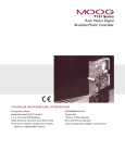
RWF40... Compact Universal Controller optimized for temperature and pressure control through the control of modulating or multi-stage burners User Manual The RWF40... controller and this User Manual are intended for use by OEMs which integrate the controller into their products! CC1B7865en 14.11.2000 Siemens Building Technologies Landis & Staefa Division 2/56 CC1B7865en 14.11.2000 Landis & Staefa Division Contents 1. Introduction.......................................................................................... 6 1.1 1.2 1.3 1.3.1 1.3.2 1.3.3 General notes................................................................................................................. 6 Description ..................................................................................................................... 6 Typographical conventions .......................................................................................... 7 Warning symbols ............................................................................................................. 7 Notification symbols......................................................................................................... 7 Presentation..................................................................................................................... 7 2. Type of unit........................................................................................... 8 2.1 Type field ........................................................................................................................ 8 3. Installation............................................................................................ 9 3.1 3.2 3.3 3.4 3.5 3.6 Installation site and climatic conditions...................................................................... 9 Dimensions .................................................................................................................... 9 Side-by-side mounting ................................................................................................ 10 Mounting in a panel cut-out ........................................................................................ 10 Cleaning the front panel.............................................................................................. 11 Removing the controller module................................................................................ 11 4. Electrical connections ....................................................................... 12 4.1 4.2 4.3 4.4 Installation notes ......................................................................................................... 12 Block diagram .............................................................................................................. 13 Assignment of terminals ............................................................................................. 14 Galvanic separation..................................................................................................... 17 5. Operating modes ............................................................................... 18 5.1 5.2 5.2.1 5.2.2 5.2.3 5.2.4 5.3 5.4 5.4.1 5.4.2 5.4.3 5.4.4 5.5 5.5.1 5.6 5.7 Low-fire operation ....................................................................................................... 18 High-fire operation....................................................................................................... 18 Modulating burner, floating output ................................................................................. 18 Modulating burner, analog output .................................................................................. 19 2-stage burner, floating output....................................................................................... 19 2-stage burner, analog output........................................................................................ 20 Safety shut-down......................................................................................................... 20 Pre-defined setpoint .................................................................................................... 20 Setpoint changeover «SP1 / SP2», analog setpoint shift .............................................. 21 Setpoint changeover «SP1» / external setpoint ............................................................ 22 Setpoint «SP1», analog / binary setpoint shift............................................................... 23 External setpoint, binary setpoint shift........................................................................... 24 Weather-dependent setpoint shift.............................................................................. 25 Heating curve slope ....................................................................................................... 26 Response threshold «Q»............................................................................................. 27 Cold start of the plant.................................................................................................. 28 Landis & Staefa Division CC1B7865en 14.11.2000 3/56 6. Operation ............................................................................................ 29 6.1 6.1.1 6.2 6.2.1 6.2.2 6.2.3 6.2.4 6.2.5 6.3 6.3.1 6.4 6.4.1 Basic display ............................................................................................................... 30 Meaning of the display and buttons .............................................................................. 30 User level ..................................................................................................................... 31 Changing the setpoints ................................................................................................. 31 Manual operation of a modulating burner ..................................................................... 33 Manual operation of a 2-stage burner ........................................................................... 33 Start self-setting ............................................................................................................ 34 Display of the software version and unit of actual value ............................................... 34 Parameter level............................................................................................................ 35 Entering parameters...................................................................................................... 35 Configuration level...................................................................................................... 35 Changing the configuration code .................................................................................. 35 7. Parameter settings ............................................................................. 36 8. Configuration...................................................................................... 38 8.1 8.3.8 8.3.9 8.3.10 C111 C112 C113 SCL SCH SCL2 SCH2 SPL SPH OFF1 OFF2 OFF3 dF1 9. Self-setting function .......................................................................... 47 9.1 9.2 Self-setting function in high-fire operation............................................................... 47 Checking the controller parameters.......................................................................... 49 10. What to do if... .................................................................................... 50 10.1 ...numbers are flashing on the display...................................................................... 50 4/56 CC1B7865en 8.2 8.3 8.3.1 8.3.2 8.3.3 8.3.4 8.3.5 8.3.6 8.3.7 inputs ........................................................................................................... 38 limit comparator, controller type, setpoint «SP1», locking..................... 40 unit address, dimensional unit, out-of-range ........................................... 44 scaling of standard signal range start, analog input 1 .................................. 45 scaling of standard signal range end, analog input 1 ................................... 45 scaling of standard signal range start, analog input 2 .................................. 45 scaling of standard signal range end, analog input 2 ................................... 46 lower setpoint limit ........................................................................................ 46 upper setpoint limit........................................................................................ 46 actual value correction for analog input 1 ..................................................... 46 actual value correction for analog input 2 ..................................................... 46 actual value correction for analog input 3 ..................................................... 46 2nd order digital filter for analog input 1 ......................................................... 46 14.11.2000 Landis & Staefa Division 11. Technical data .................................................................................... 51 11.1 11.1.1 11.1.2 11.1.3 11.1.4 11.1.5 11.2 11.2.1 11.2.2 11.2.3 11.2.4 11.2.5 11.2.6 11.3 11.3.1 11.3.2 11.3.3 Inputs ............................................................................................................................ 51 Analog input 1 (actual value) ......................................................................................... 51 Analog input 2 (external setpoint, setpoint shift)............................................................ 51 Analog input 3 (outside temperature) ............................................................................ 52 Binary input «D1» .......................................................................................................... 52 Binary input «D2» .......................................................................................................... 52 Outputs ......................................................................................................................... 52 Output 1 (release of burner) .......................................................................................... 52 Output 2, 3 (floating output) ........................................................................................... 52 Output 4 (limit comparator) ............................................................................................ 52 Output 5, analog output (option) .................................................................................... 53 Transducer supply ......................................................................................................... 53 Interface RS-485 (optional)............................................................................................ 53 General ratings ............................................................................................................ 53 Measured value accuracy.............................................................................................. 54 Measured value circuit monitoring ................................................................................. 54 Environmental conditions............................................................................................... 54 12. Current settings ................................................................................. 55 12.1 12.2 12.3 Process data ................................................................................................................ 55 Parameter level ............................................................................................................ 55 Configuration level ...................................................................................................... 56 Landis & Staefa Division CC1B7865en 14.11.2000 5/56 1. Introduction 1.1 General notes " Please read this User Manual before starting up the controller. Keep the Manual in a safe place that is accessible to all users at all times. Please help us improve the Manual. Your suggestions will be welcome. # All necessary settings and, where required, settings inside the unit are described in this User Manual, for controller software version 126.01.01. ! Section 6.2.5 «Display software version and dimensional unit» Should any difficulties arise during commissioning, you are asked not to carry out any unauthorized manipulations on the unit. You could endanger your rights under the unit warranty! Please contact us in such a case. When returning modules, assemblies or components to Landis & Staefa, the regulations of DIN EN 100 015 «Protection of electrostatically sensitive devices» must be observed. Always use the appropriate ESD packaging for transport. Please note that we cannot accept any liability for damage caused by ESD. ESD = electrostatic discharge 1.2 Description Use The RWF40... is used primarily for controlling temperature or pressure in oil- or gas-fired heating plants. It is a compact floating controller without position feedback that acts on the burner. An external switch can be used to change it over to a 2-position controller for the control of 2-stage burners. The built-in thermostat function switches the burner on and off. An adjustable response threshold is used to switch to a higher burner output (high-fire operation). Control In modulating operation, the RWF40... operates as a PIP controller. In 2-stage operation, the RWF40... provides control based on the set switching threshold. The setpoint of the RWF40... can be adjusted either on the controller itself or externally. Minimum and maximum limits for the setpoint can be set. A self-setting function is available as a standard feature. The plug-in controller module measures 96 x 48 x 127.5 mm and is especially suited for mounting in control panels. The controller incorporates 2 4-digit 7-segment displays for the actual value (red) and setpoint (green). A limit comparator is also provided and its switching behavior can be set on the configuration level. A selection can be made between 8 different limit comparator functions. Options An RS-485 interface is used for integration into a data network. Output 5 can be used as an analog output for modulating or 2-stage operation. All connections are made via screw terminals at the rear of the unit. 6/56 CC1B7865en 14.11.2000 Landis & Staefa Division 1. Introduction 1.3 Typographical conventions 1.3.1 Warning symbols The signs for Danger and Caution are used in this Manual under the following conditions: Danger This symbol is used where there may be a danger to personnel if the instructions are disregarded or not strictly followed! Caution This symbol is used where there may be damage to equipment or data if the instructions are disregarded or not strictly followed! Caution This symbol is used if pre-cautions must be taken in handling electrostatically sensitive components. # 1.3.2 Notification symbols " Note This symbol is used to draw your special attention to a remark. ! Reference This symbol refers to additional information in other Manuals, chapters or sections. abc¹. Footnote Footnotes are comments, referring to specific parts of the text. They consist of 2 parts: 1) The markings in the text are arranged as continuous superscript numbers 2) The footnote text is placed at the bottom of the page and starts with a number and a period ✱ Action This symbol indicates that a required action is described. The individual steps are indicated by an asterisk, e.g.: ✱ Press the ▲ button 1.3.3 Presentation PGM EXIT +▲ Buttons Buttons are shown in a box. Either symbols or text are possible. If a button has multiple assignments, the text shown is always the one that corresponds to the function currently used. Button combinations The representation of buttons combined with a plus sign means that first the Landis & Staefa Division EXIT button must be pressed and held down and then the other button. CC1B7865en 14.11.2000 7/56 2. Type of unit 2.1 Type field Location The type field is glued onto the housing. The type designation consists of operating voltage and type reference of the unit. Types Type of unit Description RWF40.000A97 Basic version with floating output RWF40.010A97 ¹· RWF40.001A97 With additional analog output RWF40.011A97 ¹· RWF40.002A97 With additional analog output and RWF40.012A97 ¹· RS-485 interface ¹· Packing variants # Factory setting The measured value range and the analog inputs are set at the factory. ! Accessories The supply voltage connected must match the voltage given on the type field. Chapter 8 «Configuration» Adapter frame ARG40 for plants where the predecessor model RWF32... was used, which shall be converted to the RWF40... . Bracket ARG41 for mounting the RWF40... on 35 mm DIN rails conforming to DIN 46277. Dummy cover AVA10.200/109 for covering a control panel cut-out for the RWF40... 8/56 CC1B7865en 14.11.2000 Landis & Staefa Division 3. Installation 3.1 Installation site and climatic conditions − The installation site should be free from vibrations, dust and corrosive media − The controller should be installed as far away as possible from sources of electromagnetic fields, such as frequency converters or high-voltage ignition transformers Relative humidity: < 95 % (non-condensing) Ambient temperature range: -20...+50 °C Storage temperature range: -40...+70 °C 3.2 Dimensions PGM 96 K6 91,5 48 EXIT RWF40 112 43,5 Panel cut-out to DIN 43 700 7865m01e/1200 92 +0,8 15,5 127,5 45 +0,6 Landis & Staefa Division CC1B7865en 14.11.2000 9/56 3. Installation 3.3 Side-by-side If several controllers are mounted side-by-side or above one another in a control panel, the minimum spacing must be observed, namely 30.5 mm vertically and 10.5 mm horizontally. 3.4 Mounting in a panel cut-out ✱ Place the seal provided onto the controller housing. # The unit must be installed with the seal so that no water or oil can penetrate the housing! ✱ Insert the controller from the front into the panel cut-out. 7865z08/0200 ✱ At the rear of the panel, push the fixing elements into the guide slots from the side or top. The flat faces of the fixing elements must lie against the housing. ✱ Place the fixing elements against the rear of the panel, and tighten them evenly with a screwdriver. 10/56 CC1B7865en 14.11.2000 Landis & Staefa Division 3. Installation 3.5. Cleaning the front panel The front panel can be cleaned with normal washing and rinsing agents or detergents. # It is not resistant to corrosive acids, caustic solutions and abrasive cleaners, or cleaning with high-pressure cleaners! 3.6 Removing the controller module The controller module can be removed from the housing for servicing. The rules of DIN EN 100 015 «Protection of electrostatically sensitive devices » must be adhered to for internal work on the controller! No liability will be accepted for damage caused by electrostatic discharge. 7865z09/0200 ✱ Press the ribbed surfaces together (at top and bottom) and pull out the controller module. Landis & Staefa Division CC1B7865en 14.11.2000 11/56 4. Electrical connections 4.1 Installation notes Safety regulations − The choice of cable, the installation and the electrical connections of the controller must conform to the regulations of VDE 0100 «Regulations for the installation of power circuits with nominal voltages below AC 1000 V», or appropriate local regulations − The electrical connections may only be carried out by qualified personnel − If contact with live parts is possible while working on the unit, the controller must be disconnected from the power supply at both poles Fusing − An internal current-limiting resistor interrupts the supply voltage in the event of a shortcircuit. The external fusing should not be rated above 1 A (slow). The output relays must be fused for a maximum of 2 A to prevent contact welding in the event of a shortcircuit in the load circuit ! Section 11.2 «Outputs» − No other loads may be connected to the supply terminals of the controller Interference suppression − The electromagnetic compatibility and interference suppression levels conform to standards and regulations listed under «Technical data» ! Chapter 11 «Technical data» − Input, output and supply cables should be routed separately, not parallel to one another − Arrange sensor and interface cables as twisted and screened cables, and do not run them close to power cables or components. Ground the screening to the controller at one end to the «TE» terminal − Earth the «TE» terminal of the controller to the protective earth. This cable must have a cross-sectional area that is at least as large as that of the supply cables. Earthing cables must be wired in a star configuration to a common earthing point connected to the protective earth of the supply. Earthing cables may not be looped from one controller to another Incorrect use − The unit is not suitable for installation in areas with an explosion hazard − Incorrect settings on the controller (setpoint, data of parameter and configuration levels) can affect the proper functioning of the following process or lead to damage. Safety devices that are independent of the controller, such as overpressure relief valves or temperature limiters / monitors should therefore always be provided, and only be capable of adjustment by qualified personnel. Please observe the appropriate safety regulations. Since self-setting cannot be expected to handle all possible control loops, the stability of the actual value that is produced should be checked − The analog inputs of the controller may not exceed a maximum voltage of AC 30 V or DC 50 V against «TE» ! 12/56 Section 4.3 «Galvanic separation» CC1B7865en 14.11.2000 Landis & Staefa Division 4. Electrical connections 4.2 Block diagram 3 analog inputs Release of burner Input 1: Actual value for Pt100, Ni100, Landis & Staefe Pt1000, Landis & Staefa Ni1000, thermocouples or standard signals Input 3: Outside temperature for Landis & Staefa Pt1000, Landis & Staefa Ni1000 Floating output Output 2: -Relay (regulating unit open) Output 3: - Relay (regulating unit closed) RWF40... Input 2: External setpoint, setpoint shifting for 0...1 kΩ resistor or linearized standard signals Output 1: - Relay (N.O. contact) 2 binary inputs Limit comparator Output 4: - Relay (N.O. contact) Power supply measuring transducer DC 24 V, 30 mA (short-circuit proof) For potential-free contacts Input 1: Operating mode changeover Analog output (optional) Output 5: Analog output DC 0...10 V, DC 0...20 mA DC 4...20 mA Input 2: Setpoint shifting / changeover Serial port (optional) Power supply RS-485 MOD bus protocol Baud rate 9600 AC 100 ...240 V ±10 %, 48...63 Hz 7865f01e/0301 Landis & Staefa Division CC1B7865en 14.11.2000 13/56 4. Electrical connections 4.3 Assignment of terminals Electrical connections may only be made by qualified personnel! X1+ CB X1- CG G- CA G+ TE GND D1 L1 D2 N I1 Y2 M1 Q U1 Y1 G1+ Q13 XB6 Q14 M6 XU6 B9 Q63 M9 Q64 7865z07/1199 Outputs Display LED Relay 1: release of burner Contact protection: Varistor S07K275 Terminal no. Connection diagram Q14 pole Q14 P S Q13 N.O. contact Q13 7865a11/1199 Relay 2: regulating unit opens Contact protection: RC unit ▲ Y1 N.O. contact Y1 S P Q common pole Relay 3: regulating unit closes Contact protection: RC unit Q ▼ P Y2 N.O. contact S Y2 7865a16/1099 Relay 4: limit comparator Contact protection: Varistor S07K275 K6 Q64 Q64 pole P S Q63 N.O. contact Q63 7865a15/1099 Analog output (optional) DC 0 (4)...20 mA, 0 (2)...10 V 14/56 CC1B7865en X1+ X1+ + X1- X1- - 7865a17/1099 14.11.2000 Landis & Staefa Division 4. Electrical connections Analog input 1 (actual value) Terminals Thermocouple I1 Connection diagram M1 I1 + M1 - 7865a03/1099 Resistance thermometer in 3-wire circuit M1 M1 ϑ G1+ G1+ I1 I1 Resistance thermometer in 2-wire circuit, line compensation through offset correction (OFF1) 7865a04/1099 M1 M1 ϑ G1+ G1+ 7865a05/1099 Current input DC 0...20 mA, 4...20 mA I1 M1 I1 + M1 - 7865a06/1099 Voltage input DC 0...1 V, 0...10 V U1 U1 + M1 M1 - 7865a07/1099 Analog input 2 (setpoint and setpoint shift) Terminals Connection diagram Resistance potentiometer Offset correction (OFF2) XB6 start XB6 M6 slider M6 S E M6 end Current input DC 0..20 mA, 4...20 mA A 7865a08/1099 XB6 M6 XB6 + M6 - 7865a09/1099 Voltage input DC 0...1 V, 0...10 V XU6 M6 XU6 + M6 - 7865a10/1099 Analog input 3 (outside temperature) Terminals Connection diagram Resistance thermometer in 2-wire circuit, line compensation through offset correction (OFF3) B9 B9 ϑ M9 M9 Landis & Staefa Division CC1B7865en 7865a13/1099 14.11.2000 15/56 4. Electrical connections Binary inputs Terminals Operating mode selector D1 D1 ! Section 5.2 «High-fire operation» D2 Setpoint shift / changeover Connection diagram D2 ! Sections 5.4.1...5.4.4 Common ground GND Operating voltage, interface Terminals Operating voltage AC 100...240 V ±10 %, 48...63 Hz L1 line N neutral Technical earth TE Operating voltage for transducer G+ GND 7865a12/1099 Connection diagram L1 N TE 7865a18/1099 G+ + DC 24 V / 30 mA G- G- - 7865a14/1099 Serial interface RS-485 16/56 CA CB CG CC1B7865en 14.11.2000 RxD / TxD+ RxD / TxDGND Landis & Staefa Division 4. Electrical connections 4.4 Galvanic separation The diagram shows the maximum potential differences that may exist between the function modules in the controller. 3 analog inputs Limit comparator Input 1: Actual value for Pt100, Ni100, Landis & Staefa Pt1000, Landis & Staefa Ni1000 thermocouples or standard signals Input 2: External setpoint, setpoint shift for resistance 0...1 k Ω , or standard signals Input 3: Outside temperature for Landis & Staefa Pt1000, Landis & Staefa Ni1000 2 binary inputs for potential-free contacts D1: operating mode changeover D2: setpoint shift / changeover Output 4: - Relay (N.O. contact) Release of burner L1, N: Output 1: - Relay (N.O. contact) Floating output L1, N: Output 2: - Relay (reg. unit opens) Output 3: - Relay (reg. unit closes) Operating voltage L1, N: Transducer supply DC 24 V , 30 mA (short-circuit proof) AC 100...240 V ± 10 %, 48...63 Hz Analog output (optional) Output 5: Analog output, DC 0...10 V, DC 0...20 mA, 4...20 mA Max. insulation voltages: Serial interface RS-485 (optional) DC 50 V AC 400 V MOD bus protocol Baud rate 9600 AC 4000 V Technical earth TE 7865f07e/0301 Landis & Staefa Division CC1B7865en 14.11.2000 17/56 5. Operating modes 5.1 Low-fire operation Low-fire operation means that only small amounts of heat are drawn from the boiler. A 2position controller maintains the setpoint, switching the burner on and off like a thermostat. Thermostat function This control mode is therefore also known as thermostat function. An adjustable switching differential ensures that the switching frequency of the burner can be selected to reduce wear. Modulating and 2-stage operation: Actual value between «HYS1» and «HYS3» HYS3 W HYS1 7865w03/1099 5.2 High-fire operation High-fire operation means that large amounts of heat are drawn from the boiler, so that the burner is on all the time. If the heating load during the thermostat operation rises to a level where the actual value begins to fall below the switch-on threshold «HYS1», the controller does not immediately switch over to a higher burner output, but first makes a dynamic test of the control deviation and switches to the higher output only when an adjustable threshold «Q» is exceeded (A). ! Operating mode changeover Section 5.6 «Response threshold Q» − In high-fire operation, depending on the application, the burner can be fired in modulating or 2-stage operation, with a larger amount of fuel than in low-fire operation. The binary input «D1» can be used to switch between modulating and 2stage operation − When the contact is open: modulating burner operation − When the contact is closed: 2-stage burner operation 5.2.1 Modulating burner, floating output In diagram area (1), the thermostat function is active. The modulating mode of burner operation is shown in area (2). In high-fire operation, a floating controller acts on an actuator through relay 2 (open) and relay 3 (close). B 7865w07/1099 db HYS3 W HYS1 q q A A (2) (1) (3) In area (3), the actual value exceeds the upper switch-off threshold «HYS3» and the controller switches off the burner (B). The controller only starts low-fire operation when the level falls below the switch-on threshold «HYS1» again. If «Q» is exceeded, the controller switches to high-fire operation (A). ! 18/56 Section 5.6 «Response threshold Q» CC1B7865en 14.11.2000 Landis & Staefa Division 5. Operating modes 5.2.2 Modulating burner, analog output In diagram area (1), the thermostat function is active. In area (2), the controller is controlling to the adjusted setpoint. B 7865w05/1099 HYS3 W HYS1 q q A A 100% X1 0% (2) (1) The positioning signal is delivered as a standard signal via the analog output. " ! The modulating controller must be available and configured in the unit (optional). Section 8.2 «C112 Limit comparator, controller type, setpoint «SP1», locking» 5.2.3 2-stage burner, floating output In diagram area (1), the thermostat function is active. In area (2), a 2-position controller acts on the second stage, via relay 2 (open) and relay 3 (close) by switching it into the circuit at the switch-on threshold «HYS1» / and out of circuit at the switch-off threshold «HYS2». B 7865w06/1099 HYS3 HYS2 W HYS1 q q A A I II (1) (2) In area (3), the actual value exceeds the upper switch-off threshold «HYS3» and the controller shuts down the burner (B). The controller only starts low-fire operation when the level falls below the switch-on level «HYS1» again. If «Q» is exceeded, the controller switches to high-fire operation (A). ! Landis & Staefa Division Section 5.6 «Response threshold Q» CC1B7865en 14.11.2000 19/56 5. Operating modes 5.2.4 2-stage burner, analog output In this case, a standard binary signal switches the second stage into circuit with analog output «X1» on reaching the switch-on threshold «HYS1» and switches it out of circuit at the lower switch-off threshold «HYS2». B HYS3 HYS2 W HYS1 q 7865w04/1099 q A A 100% X1 0% (1) " ! (2) The modulating controller must be available and configured in the unit (optional). Section 8.2 «C112 Limit comparator, controller type, setpoint «SP1», locking» 5.3 Safety shut-down In the event of a sensor failure, the controller cannot monitor the actual value of the boiler temperature (analog input 1). A safety shut-down is automatically carried out to guard against overheating. This also applies to the acquisition of the external setpoint at analog input 2. Functions − − − − Burner off Floating output for closing the regulating unit Self-setting is ended Manual operation is ended 5.4 Pre-defined setpoint The setpoint is pre-selected within pre-set limits with the buttons, an external analog signal or the interface. It is possible to shift the setpoint, by either an analog or a binary signal, to influence it according to the weather or to change it with an external contact. 20/56 CC1B7865en 14.11.2000 Landis & Staefa Division 5. Operating modes 5.4.1 Setpoint changeover «SP1 / SP2», analog setpoint shift C111: XX1X ... XX3X Outside sensor C111 and C112 are described in chapter 8 Heating curve slope H Setting: 0.0 ... 4.0 Weather-dependent setpoint shift: No Yes C112: XX0X C112: XX1X SP1 via buttons SP1 via outside sensor C111: XXX2 Section 5.4.4 "External setpoint, binary setpoint shift" C111: XXX1 C111: XXX0 Setpoint changeover No function D2 open Setpoint SP2 SP2 via buttons D2 closed + C111: X6XX ... XAXX Analog setpoint shift SPH The setpoints SP1 and SP2 are entered at the user level. Section 6.2 "User level" SPL Connection of binary input D2 Section 4.2 "Assignment of terminals" 7865f05e/1100 Landis & Staefa Division CC1B7865en 14.11.2000 Active setpoint 21/56 5. Operating modes 5.4.2 Setpoint changeover «SP1» / external setpoint C111: XX1X ... XX3X Outside sensor C111 and C112 are described in chapter 8 Heating curve slope H Setting: 0.0 ... 4.0 Weather-dependent setpoint shift: No Yes C112: XX0X C112: XX1X SP1 via buttons SP1 from outside sensor C111: X1XX ... X5XX External setpoint C111: XXX2 C111: XXX0 C111: XXX1 No function Setpoint changeover Section 5.4.4 "External setpoint, binary setpoint shift" D2 closed D2 open SPH Setpoint SP1 is entered at the user level Section 6.2 "User level" Connection of binary input D2 Section 4.2 "Assignment of terminals" SPL 7865f03e/1100 Active setpoint 22/56 CC1B7865en 14.11.2000 Landis & Staefa Division 5. Operating modes 5.4.3 Setpoint «SP1», analog / binary setpoint shift C111: XX1X ... XX3X Outside sensor C111 and C112 are described in chapter 8 Heating curve slope H Setting: 0.0 ... 4.0 Weather-dependent setpoint shift: No Yes C112: XX0X C112: XX1X SP1 via buttons SP1 via outside sensor C111: X6XX ... XAXX + Analog setpoint shift C111: XXX1 C111: XXX2 Sections 5.4.1 and 5.4.2 "Setpoint changeover ..." Binary setpoint shift C111: XXX0 No function D2 closed + dSP 0,0 D2 open The values dSP and SP1 are entered at the user level Section 6.2 "User level" Connection of binary input D2 Section 4.2 "Assignment of terminals" Landis & Staefa Division CC1B7865en 14.11.2000 SPL 7865f04e/1100 SPH Active setpoint 23/56 5. Operating modes 5.4.4 External setpoint, binary setpoint shift C111: X1XX ... X5XX C111 and C112 are described in chapter 8 External setpoint C111: XXX1 C111: XXX2 Sections 5.4.1 and 5.4.2 "Setpoint changeover ..." Binary setpoint shift C111: XXX0 No function D2 closed + dSP 0 D2 open SPH The values of dSP and SP1 are entered at the user level Section 6.2 "User level" SPL Connection of binary input D2 Section 4.2 "Assignment of terminals" 7865f02e/1200 24/56 CC1B7865en 14.11.2000 Active setpoint Landis & Staefa Division 5. Operating modes 5.5 Weather-dependent setpoint shift The RWF40... can be configured in such a way that if a Landis & Staefa Ni1000 outside sensor (e.g. QAC22) is connected, a weather-dependent setpoint shift is implemented. The minimum and maximum setpoint values can be set by the lower setpoint limit «SPL» and the upper setpoint limit «SPH». Parameter «P» can be used to apply a parallel displacement to the heating curve. # " Parallel displacement of heating curve Landis & Staefa Division ! Each RWF40... must have its own separate outside sensor connected (no parallel connection)! This function has been optimized for space heating combined with domestic hot water heating. Chapter 7 «Parameter settings» CC1B7865en 14.11.2000 25/56 5. Operating modes 5.5.1 Heating curve slope Slope «H» of the heating curve can be used to adjust the setpoint in response to the outside temperature, as shown in the diagram. The common origin of the heating curves is set at (20 °C / 20 °C). The effective range of the weather-adjusted setpoint is restricted by the setpoint limits «SPH» and «SPL». H larger Setpoint (°C) HYS3 SPH H smaller HYS1 SPL +20 +20 10 0 -10 Outside temperature (°C) 7865d01e/1199 «HYS1» is the switch-on point for the burner, and «HYS3» is the switch-off point. As already described, they act with the set shift relative to the weather-controlled setpoint. 26/56 ! Section 5.2.1 «Modulating burner, floating output» ! Section 5.2.2 «Modulating burner, analog output» CC1B7865en 14.11.2000 Landis & Staefa Division 5. Operating modes 5.6 Response threshold «Q» The response threshold «Q» defines how long and how low the actual value can drop before the system switches over to high-fire operation. An internal mathematical calculation using an integration function determines the sum of all the areas Qeff = Q1 + Q2 + Q3 , as shown in the diagram. This only takes place when the control deviation (x-w) falls below the value for the switching threshold «HYS1». If the actual value increases, integration is stopped. If «Qeff» exceeds the pre-set response threshold «Q» (can be adjusted at the parameter level), this causes the second stage of the burner to be switched on or - in the case of a floating controller / modulating controller – the regulating unit to open. If the actual boiler temperature reaches the required setpoint, Qeff is reset to 0 . Temperature (°C) x w HYS1 Q 1 Q 2 Q3 t Q =0 7865d19e/1199 eff Actual value monitoring ensures that the switching frequency is kept low in the transitional range from low- to high-fire operation in order to reduce wear. Landis & Staefa Division CC1B7865en 14.11.2000 27/56 5. Operating modes 5.7 Cold start of the plant When a heating system is switched off for a longer period of time, the actual value will fall. To achieve a faster control response, the controller starts immediately in high-fire operation as soon as the control deviation (x-w) has dropped below a certain limit value. This limit is calculated as follows: Limit value = 2 * (HYS1-HYS3) In that case, response threshold «Q» is inactive, independent of the operating mode and the controlled variable (temperature, pressure). Example Operating mode: modulating, floating output HYS1 = -3 K HYS3 = +5 K w = 60 °C Limit value = 2 * (-3 - 5) = 2 * (-8) = -16 K At an actual value below 44 °C, the heating up procedure starts immediately in high-fire operation, instead of in thermostat mode. °C HYS3 W db 2 x (HYS1 - HYS3) HYS1 X t 7865d20/1099 28/56 CC1B7865en 14.11.2000 Landis & Staefa Division 6. Operation Assignment of levels All levels can be accessed from the basic display via the PGM button, as shown in the diagram. The upper actual value display (red) indicates the actual value and the parameter values for the various levels. The setpoint and the parameters are indicated in the lower setpoint display (green). BASIC DISPLAY 1. USER LEVEL 1. Min. 2 s or time-out (approx. 30 s) Min. 2 s PARAMETER LEVEL 1. Min. 2 s CONFIGURATION LEVEL 7865f08e/1299 1) Landis & Staefa Division After using «PGM» to step through all the parameters of a level, an automatic return occurs after the last parameter has been confirmed. CC1B7865en 14.11.2000 29/56 6. Operation 6.1 Basic display The diagram shows the RWF40... after switching on power. This condition is called the basic display. The actual value and the currently active setpoint are shown here. Manual operation, self-setting, the user, parameter and configuration levels can be activated from here. 6.1.1 Meaning of the display and buttons Release of burner Regulating unit CLOSE / 1st stage Regulating unit OPEN / 2nd stage 2-stage operation Actual value display (red) Setpoint display (green) 503 639 Manual operation Limit comparator Decrease value Increase value PGM button EXIT button 7865p02e/0200 30/56 CC1B7865en 14.11.2000 Landis & Staefa Division 6. Operation Initialization All displays are lit up; the setpoint display flashes for about 10 seconds after switching on power. Manual operation The actual value is indicated on the upper display. The LED for manual operation is on. Depending on the operating mode and the type of controller, the setpoint or the level of the manual actuator position is shown on the setpoint display (green). ! Self-setting function Section 6.2.2 «Manual operation of a modulating burner» The actual value is shown on the actual value display (red) and the text «tunE» flashes on the setpoint display (green). ! Section 9.1 «Self-setting function in high-fire operation» Actual value display flashes ! Chapter 10 «What to do if...» 2-stage operation ! Section 5.2 «High-fire operation» Time-out " If there is no action by the operator, the controller returns automatically to the basic display after about 30 seconds. 6.2 User level This level is started from the basic display. Setpoints «SP1», «SP2 / dSP» can be altered, and the analog inputs «E2» (external setpoint / setpoint shift) and «E3» (outside temperature) can be displayed. 6.2.1 Changing the setpoints To alter «SP1», «SP2» or «dSP»: ✱ Change to the user level with PGM ✱ Alter the setpoint «SP1» with ▼ and ▲ ✱ Change to setpoint «SP2» or «dSP» with PGM ✱ Alter the setpoint «SP2» or «dSP» with ▼ and ▲ ✱ Return to the basic display with " Landis & Staefa Division EXIT or automatically by time-out after about 30 s After 2 seconds, the value that is set will automatically be adopted. The value can only change within the permitted value range CC1B7865en 14.11.2000 31/56 6. Operation Basic display 60.3 65.0 PGM User level (Display depends on code 111) EXIT 65.0 SP 1 PGM Depending on the configuration of binary input 2: - dSP -Sp2 EXIT 70.0 SP 2 or 10.0 dSP PGM Measurement of the outside temperature via analog input 3 EXIT 10.0 tA PGM Measurement of the external setpoint or a setpoint shift via analog input 2 50.0 SP.E PGM 7865f06e/1199 32/56 CC1B7865en 14.11.2000 Landis & Staefa Division 6. Operation 6.2.2 Manual operation, modulating burner ✱ Press EXIT for 5 seconds The LED above the hand symbol lights up. Floating controller ✱ Change the regulating unit’s position with ▲ and ▼ Relay 2 opens the regulating unit as long as ▲ is pressed. Relay 3 closes the regulating unit as long as ▼ is pressed. The LEDs for the regulating units indicate if «OPEN» or «CLOSE» is activated. Modulating controller ✱ Change the regulating unit’s position with ▲ and ▼ The analog output delivers the regulating unit’s position that was entered. ✱ Return to automatic operation by pressing " Thermostat mode EXIT for 5 seconds When manual operation is activated, the regulating unit’s position is set to 0 until another entry with the buttons is made. Manual operation can only be activated if the thermostat function has set relay 1 to active. If the thermostat function sets relay 1 to inactive during manual operation, manual operation is terminated. 6.2.3 Manual operation, 2-stage burner ✱ Press EXIT for 5 seconds ✱ Press ▲ briefly − Relay 2 is active, relay 3 is inactive − Analog output (optional) delivers DC 10 V The regulating unit opens ✱ Or press ▼ briefly − Relay 2 is inactive, relay 3 is active − Analog output (optional) delivers DC 0 V The regulating unit closes ✱ Return to automatic operation by pressing " Landis & Staefa Division EXIT for 5 seconds If the thermostat function sets relay 1 to inactive during manual operation, manual operation is terminated. CC1B7865en 14.11.2000 33/56 6. Operation 6.2.4 Start self-setting ✱ Start self-setting with ✱ Cancel with ▲ PGM +▼ PGM 7865z10/1199 When «tunE» stops flashing, self-setting has stopped. ✱ Accept the parameters that have been determined by pressing ▲ (press the button for at least 2 seconds!) " It is not possible to start «tunE» in manual operation or thermostat operation. 6.2.5 Display of the software version and unit of actual value ✱ Press PGM +▲ Available units: °C, °F and % (for standard signals) PGM + 7865z11/1199 34/56 CC1B7865en 14.11.2000 Landis & Staefa Division 6. Operation 6.3 Parameter level The parameters involved in the adaptation of the controller to the controlled system are set here after the system has been started up. Within the level, you can proceed to the next parameter by pressing " 6.3.1 Entering parameters PGM . The display of the individual parameters depends on the type of controller. The entry and alteration of parameters is made through a continuous alteration of the value. The longer you keep the button pressed, the faster the rate of change becomes. ✱ Increase value by pressing ▲ ✱ Reduce value by pressing ▼ ✱ Accept entry by pressing PGM or ✱ Cancel entry by pressing " ! EXIT After 2 seconds, the value that is set will automatically be accepted. The value can only change within the permitted value range. Chapter 7 «Parameter settings» 6.4 Configuration level The settings made here are those required for commissioning a specific installation and therefore rarely need to be altered, such as acquisition of measured value or type of controller. Within the level, you can proceed to the next parameter by pressing PGM . 6.4.1 Changing the configuration code ✱ Select position by pressing ▼ (position flashes!) ✱ Alter value by pressing ▲ ✱ Accept code by pressing PGM or ✱ Cancel entry by pressing ! Landis & Staefa Division EXIT Chapter 8 «Configuration» CC1B7865en 14.11.2000 35/56 7. Parameter settings The parameter is shown on the lower setpoint display (green) and the value on the upper / actual value display (red). AL 10 7865p06/0200 Parameter Display Value range AL -1999...+9999 digit Limit value for limit comparator 1) Factory Remarks setting 0 Output 4 AL HYSt 7865d10e/0300 Measured value w ! Chapter 8.2 «C112 – limit comparator, controller type, setpoint «SP1», locking» HYSt 0...999.9 digit 1 Pb.1 dt 0.1...999.9 digit 10 0...9999 s 80 Integral action time rt 0...9999 s 350 Dead band (neutral zone) 1) db 0...999.9 digit 1 Switching differential for limit comparator 1) Proportional band 1) Derivative time Switching differential at the edges for the limit comparators ! Chapter 8.2 «C112 – limit comparator, controller type, setpoint «SP1», locking» Affects the P-response of the controller Affects the D-response of the controller. Within dt = 0, the controller has no Dresponse. For modulating controllers, dt = rt / 4 or 0 must be entered. Affects the I-response of the controller. With rt = 0, the controller has no Iresponse For floating output Y db 100% X W -100% 7865d11/1099 1) 36/56 This parameter is affected by the setting of the decimal place. CC1B7865en 14.11.2000 Landis & Staefa Division 7. Parameter settings The parameter is shown on the lower / setpoint display (green) and the value on the upper / actual value display (red). AL 10 7865p06/0200 Display Value range Factory setting tt 10...3000 s 15 s Switch-on threshold for burner stage II 1) HYS1 0...-199.9 digit -5 ! Section 5.5.1 «Heating curve slope» Switch-off threshold stage II 1) HYS2 0...HYS3 digit 3 ! Section 5.2 «High-fire operation» Upper switch-off threshold 1) HYS3 0...999.9 digit 5 ! Section 5.2 «High-fire operation» q 0...999.9 0 ! Section 5.6 «Response threshold Parameter Actuator running time Response threshold Remarks Utilized running time of the valve for floating controllers Q» Heating curve slope H 0...4 1 ! Section 5.5.1 «Heating curve slope» Parallel displacement 1) P -90...+90 0 ! Section 5.5 «Weather-dependent setpoint shift» 1) Landis & Staefa Division This parameter is affected by the setting of the decimal place. CC1B7865en 14.11.2000 37/56 8. Configuration 8.1 C111 inputs 0000 C111 7865p03/0200 Analog input 1 Pt100, 3-wire, IEC 751 Pt100, 2-wire, IEC 751 Ni100, 3-wire, DIN 43760 Ni100, 2-wire, DIN 43760 Landis & Staefa Pt1000, 3-wire, IEC 751 Landis & Staefa Pt1000, 2-wire, IEC 751 Landis & Staefa Ni1000, 3-wire, DIN 43760 Landis & Staefa Ni1000, 2-wire, DIN 43760 Landis & Staefa Ni1000, 3-wire Landis & Staefa Ni1000, 2-wire NiCr-Ni / K Cu-CuNi / T NiCroSil-NiSil / N Fe-CuNi / J Standard signal DC 0…20 mA Standard signal DC 4…20 mA Standard signal DC 0…10 V Standard signal DC 0…1 V 0 1 2 3 4 5 6 7 8 9 A b C d E F G H Analog input 2 No function External setpoint, 1 kΩ resistance potentiometer External setpoint, DC 0…20 mA External setpoint, DC 4…20 mA External setpoint, DC 0…10 V External setpoint, DC 0…1 V Analog setpoint shift, 1 kΩ resistance potentiometer Analog setpoint shift, DC 0…20 mA Analog setpoint shift, DC 4…20 mA Analog setpoint shift, DC 0…10 V Analog setpoint shift, DC 0…1 V 38/56 CC1B7865en 0 1 2 3 4 5 6 7 8 9 A 14.11.2000 Landis & Staefa Division 8. Configuration 0000 C111 7865p03/0200 Analog input 3 No function Outside sensor Landis & Staefa Pt1000, 2-wire, IEC 751 Outside sensor Landis & Staefa Ni1000, 2-wire, DIN 43760 Outside sensor Landis & Staefa Ni1000, 2-wire 0 1 2 3 Function of binary input «D2» No function Setpoint changeover Setpoint shift (binary) 0 1 2 Factory setting Landis & Staefa Division 9 CC1B7865en 14.11.2000 0 3 0 39/56 8. Configuration 8.2 C112 limit comparator, controller type, setpoint «SP1», locking 0000 C112 7865p04/0200 Limit comparator No function (lk off) lk1, input 1 lk2, input 1 lk3, input 1 lk4, input 1 lk5, input 1 lk6, input 1 lk7, input 1 lk8, input 1 lk7, input 2 lk8, input 2 lk7, input 3 lk8, input 3 0 1 2 3 4 5 6 7 8 9 A b C Controller type Floating controller Modulating controller DC 0…20 mA Modulating controller DC 4…20 mA Modulating controller DC 0...10 V 0 1 2 3 Setpoint «SP1» «SP1» via buttons «SP1» with outside sensor (analog input 3 must be configured) 0 1 Locking No locking Locking of configuration level Locking of parameter level Locking of buttons # 0 1 2 3 Locking of the buttons can be entered only once and adapted with PGM . After this, all button operations are locked and can only be enabled again by the manufacturer! Factory setting 40/56 0 CC1B7865en 14.11.2000 0 1 0 Landis & Staefa Division 8. Configuration Function Ik1 Window function: relay «K6» is active when the measured value lies within a window around the setpoint (w). Example: w = 80 °C, AL = 5, HYSt = 2 Measured value rising: relay «K6» switches on at 76 °C and off at 86 °C. Measured value falling: relay «K6» switches on at 84 °C and off at 74 °C. Output 4 AL HYSt 7865d10e/0300 Function Ik2 Measured value w As for lk1, but with inverted switching function. Output 4 AL HYSt 7865d09e/0300 Measured value w HYSt = switching differential of the window edges AL = interval from setpoint (half the window-width) Function Ik3 Lower limit signaling Function: relay inactive when measured value < (setpoint – limit value). Example: w = 80 °C, AL = 10, HYSt = 2 Measured value rising: relay «K6» switches on at 71 °C. Measured value falling: relay «K6» switches off at 69 °C. Output 4 AL HYSt 7865d04e/0300 Landis & Staefa Division CC1B7865en w Measured value 14.11.2000 41/56 8. Configuration Function Ik4 As for lk3, but with inverted switching function. Output 4 AL HYSt 7865d03e/0300 Measured value w HYSt = switching differential AL = interval from setpoint ! Function Ik5 Chapter 7 «Parameter settings» Upper limit signaling Function: relay inactive when measured value > (setpoint + limit value). Example: w = 80 °C, AL = 10, HYSt = 2 Measured value rising: relay «K6» switches off at 91 °C. Measured value falling: relay «K6» switches on at 89 °C. Output 4 AL HYSt 7865d05e/0300 Function Ik6 Measured value w As for lk5, but inverted switching function. Output 4 AL HYSt 7865d06e/0300 42/56 CC1B7865en Measured value w 14.11.2000 Landis & Staefa Division 8. Configuration Function Ik7 The switching point is independent of the controller setpoint; only the limit value «AL» determines the switching point. Function: relay is active when measured value > limit value. Example: AL = 50, HYSt = 2 Measured value rising: relay «K6» switches on at 51 °C. Measured value falling: relay «K6» switches off at 49 °C. Output 4 HYSt 7865d07e/0300 Function Ik8 AL Measured value As for lk7, but with inverted switching function. Output 4 HYSt 7865d08e/0300 Measured value AL HYSt = switching differential AL = limit value ! Landis & Staefa Division Chapter 7 «Parameter settings» CC1B7865en 14.11.2000 43/56 8. Configuration 8.3 C113 instrument address, dimensional unit, out-of-range # The setting for the decimal place affects actual value-dependent parameters! 0000 C113 7865p05/0200 Unit address Address 0 Address 1 ... Address 99 # 0 0 0 1 ... 9 9 Decimal places, dimensional unit No decimal place, °C One decimal place, °C No decimal place, °F One decimal place, °F 0 1 2 3 Signal for out-of-range Limit comparators OFF Limit comparators ON 0 1 Factory setting 44/56 0 CC1B7865en 14.11.2000 1 1 0 Landis & Staefa Division 8. Configuration 8.3.1 «SCL» scaling of standard signal range start, analog input 1 Example SCL = 20; SCH = 100 °C 0 mA (start) corresponds to a measured value of 20 °C 0 mA 20 mA 0 °C 20 °C 100 °C Value range: -1999...+9999 digit Factory setting: 0 digit 8.3.2 «SCH» scaling of standard signal range end, analog input 1 Example SCH = 80; SCL = 0 °C 20 mA (end) corresponds to a measured value of 80 °C 0 mA 20 mA 0 °C 80 °C 100 °C Value range: -1999...+9999 digit Factory setting: 100 digit 8.3.3 «SCL2» scaling of standard signal range start, analog input 2 Example SCL2 = 20: 0 mA corresponds to a measured value of 20 °C, as already described Value range: -1999...+9999 digit Factory setting: 0 digit Landis & Staefa Division CC1B7865en 14.11.2000 45/56 8. Configuration 8.3.4 «SCH2» scaling of standard signal range end, analog input 2 Example SCH2 = 80: 20 mA corresponds to a measured value of 80 °C, as already described Value range: -1999...+9999 digit Factory setting: 100 digit 8.3.5 «SPL» lower setpoint limit The controller restricts the setpoints to the value that is set. Value range: -1999...+9999 digit Factory setting: 0 digit 8.3.6 «SPH» upper setpoint limit The controller restricts the setpoints to the value that is set. Value range: -1999...+9999 digit Factory setting: 100 digit 8.3.7 «OFF1» actual value correction for analog input 1 The actual value correction can be used for correction of the measured value upwards or downwards by a specific amount. It is also used for line compensation when resistance thermometers are connected in a 2-wire circuit. Value range: -1999...+9999 digit Factory setting: 0 digit Example Measured value Offset Displayed value 294.7 +0.3 295 295.3 -0.3 295 8.3.8 «OFF2» actual value correction for analog input 2 Value range: -1999...+9999 digit Factory setting: 0 digit 8.3.9 «OFF3» actual value correction for analog input 3 Value range: -1999...+9999 digit Factory setting: 0 digit 8.3.10 «dF1» 2nd order digital filter for analog input 1 Value range for filter time constant: 0...100 s Factory setting: 1 seconds 46/56 CC1B7865en 14.11.2000 Landis & Staefa Division 9. Self-setting function 9.1 Self-setting function in high-fire operation " «tunE» is only possible in high-fire operation, in the «modulating burner» mode. The self-setting function «tunE» is a pure software function unit that is integrated into the controller. In the «modulating» mode of operation, «tunE» tests the response of the controlled system to steps of the positioning signal according to a special procedure. A complex control algorithm uses the response of the controlled system (actual value) to calculate and store the control parameters for a PID or PI controller (set dt = 0!). The «tunE» procedure can be repeated as often as required. Self-setting W Start PID controller settings Identification of the controlled system Controller Controlled system Y X 7865f09e/1199 2 procedures The «tunE» function uses 2 different methods that are automatically selected depending on the dynamic state of the actual value and the difference from the setpoint at the start. «tunE» can be started from within any dynamic actual value sequence. If there is a large difference between actual value and setpoint when «tunE» is activated, a switching line is established around which the controlled variable performs forced oscillations during the self-setting procedure. The switching line is set at such a level that the actual value should not exceed the setpoint. x Start w Switching level t 7865d12e/1199 With a small deviation between setpoint and actual value, for instance when the controlled system has stabilized, a forced oscillation is performed around the setpoint. Landis & Staefa Division CC1B7865en 14.11.2000 47/56 9. Self-setting function x Start w 7865d13/1099 t The controlled system data which are recorded for the forced oscillations are used to calculate the controller parameters «rt, dt, Pb.1» and a filter time constant for actual value filtering that is optimized for this controlled system. Conditions − High-fire operation in the «modulating burner» mode − The thermostat function (relay 1) must be constantly activated, otherwise «tunE» will be cancelled and no optimized controller parameters will be adapted − The above mentioned actual value oscillations during self-setting may not exceed the upper threshold of the thermostat function (increase if necessary, and lower the setpoint) 48/56 CC1B7865en 14.11.2000 Landis & Staefa Division 9. Self-setting function 9.2 Checking the controller parameters The optimum adjustment of the controller to the controlled system can be checked by recording a start-up sequence with the control loop closed. The following diagrams indicate possible incorrect adjustments, and their correction. The response to a setpoint change is shown here for a 3rd order controlled system for a PID controller. The method used for adjusting the controller parameters can, however, also be applied to other controlled systems. A favorable value for «dt» is «rt» / 4. Example «PB too small» «PB too large» x x w w t 7865d17/1099 t 7865d15/1099 «rt, dt» too small «rt, dt» too large x x w w t 7865d16/1099 t 7865d14/1099 Optimum adjustment x w 7865d18/1099 Landis & Staefa Division CC1B7865en t 14.11.2000 49/56 10. What to do, if ... 10.1 ...numbers are flashing on the display This is an indication that a measured value is not being acquired correctly. " ! Display The detection of measured value range crossings depends on the type of sensor used. Section 11.3.2 «Measured value circuit monitoring» Description Actual value display (red) shows «1999» flashing. Setpoint display shows the setpoint. 1999 # Cause / controller behavior / remedy Overrange or underage on analog input 1. The actual value is not being measured. Controller initiates lockout. ! Section 5.3 «Safety shut-down» The limit comparator responds to analog input 1 according to the configuration (C113). 60.0 ✱ Check the electrical connections for open-circuit of sensor 7865p08/0200 When analog input 3 is configured for outside temperature (C111) and the measured value is called up, the actual value display (red) shows «1999» flashing. 1999 tA # Overrange or underage on analog input 3. The outside temperature is not being measured! The weather-dependent setpoint is inactive! ✱ Check the electrical connections for open-circuit of sensors 7865p10/0200 When analog input 2 is configured (C111) and the measured value is called up, the process value display (red) shows «1999» flashing. 1999 SP.E # Overrange or underage on analog input 2. The external setpoint is not being measured. Controller initiates lockout ! Section 5.3 «Safety shut-down» ✱ Check the electrical connections for open-circuit of sensors 7865p09/0200 Actual value display (red) shows «XXXXXX». Setpoint display (green) shows «1999» flashing. 53.2 # Overrange or underage on analog input 2. The setpoint shift is not being measured. Controller initiates lockout ! Section 5.3 «Safety shut-down» 1999 ✱ Check the electrical connections for open-circuit of sensor 7865p07/0200 50/56 CC1B7865en 14.11.2000 Landis & Staefa Division 11. Technical data 11.1 Inputs 11.1.1 Analog input 1 (actual value) For resistance thermometers, thermocouples or standard signals with 2nd order digital filter (configurable). Resistance thermometers In 2-wire or 3-wire circuit: Type Pt100, Landis & Staefa Pt1000, IEC 751 Ni100, Landis & Staefa Ni1000, DIN 43760 Landis & Staefa Ni1000 Measured value range -200...+850 °C -60...+250 °C -50...+160 °C Line resistance: < 30 Ω Line compensation Not required for a 3-wire circuit. When using a resistance thermometer in a 2-wire circuit, line compensation can only be made by means of the offset correction. Thermocouples Type Fe-CuNi «J» NiCr-Ni «K» Cu-CuNi «T» NiCrSi-NiSi «N» Measured value range -200...+1000 °C -200...+1372 °C -200...+400 °C -100...+1300 °C Cold-junction temperature: internal Standard signals Signal DC 0...10 V DC 0...1 V DC 0...20 mA DC 4...20 mA Internal resistance Ri Voltage drop ∆Ue Ri = 2 MΩ Ri = 2 MΩ ∆Ue = < 1 V ∆Ue = < 1 V Sampling time: 210 ms 11.1.2 Analog input 2 (external setpoint, setpoint shift) Resistance measured value 0…1 kΩ standard signals without linearization. Potentiometer With 2-wire circuit R = 0…1 kΩ Standard signals Signal DC 0...10 V DC 0...20 mA DC 4...20 mA Internal resistance Ri Voltage drop ∆Ue Ri = 2 MΩ ∆Ue = 1 V ∆Ue = 1 V Sampling time: 630 ms Landis & Staefa Division CC1B7865en 14.11.2000 51/56 11. Technical data 11.1.3 Analog input 3 (outside temperature) For resistance thermometers in a 2-wire circuit, with fixed filter time constants (21 h 18 min for the weather-dependent setpoint enable) Resistance thermometer Type Landis & Staefa Pt1000 Landis & Staefa Ni1000, DIN 43760 Landis & Staefa Ni1000 Measured value range -200...+850 °C -60...+250 °C -50...+160 °C Sampling time: 6 seconds 11.1.4 Binary input «D1» Potential-free contact for operating mode changeover: − Modulating burner, when the contact is open, LED on the front is not lit − 2-stage burner, when the contact is closed, LED on the front is lit 11.1.5 Binary input «D2» Potential-free contact for the following functions, depending on the configuration: − No function − Setpoint shift − Setpoint changeover 11.2 Outputs 4 relay outputs, 1 analog output (optional) and a transducer supply are provided as standard. 11.2.1 Output 1 (release of burner) Relay output (N.O. contact) Contact rating: Contact life: Internal contact protection: AC 24…240 V, 2 A at p.f. (cos ϕ) > 0.6 > 2 x·105 switching cycles at rated load Varistor S07K275 11.2.2 Output 2, 3 (floating output) 2 relay outputs (N.O. contacts) with a common pole, for regulating unit open / close Contact rating: Contact life: Internal contact protection: AC 24…240 V, 2 A at cos ϕ > 0.6 > 2 x·105 switching cycles at rated load RC combination (C = 2.5 nF, R = 100 Ω) 11.2.3 Output 4 (limit comparator) Relay output (N.O. contact) Contact rating: Contact life: Internal contact protection: 52/56 CC1B7865en AC 24…240 V, 2 A at cos ϕ > 0.6 > 2 x·105 switching cycles at rated load Varistor S07K275 14.11.2000 Landis & Staefa Division 11. Technical data 11.2.4 Output 5, analog output (option) Analog output, electrically isolated from the analog inputs: ∆U < AC 30 V , ∆U < DC 50 V Standard signals DC 0…10 V (short-circuit proof) DC 0…20 mA DC 4…20 mA Load, burden Load = > 500 Ω Burden = < 500 Ω Burden = < 500 Ω Accuracy: ±0.25 % ±50 ppm / K 11.2.5 Transducer supply DC 24 V, 30 mA (short-circuit proof) 11.2.6 Interface RS-485 (optional) Baud rate: Protocol: Unit address: 9600 MOD bus 1…99 Galvanic separation between supply voltage, analog inputs and outputs. ! Section 4.3 «Galvanic separation» 11.3 General ratings Landis & Staefa Division Weight: approx. 430 g Data backup: EEPROM Operating voltage: AC 100…240 V ±10 %, 48…63 Hz Power consumption: approx. 5 VA Electrical connection: at the rear, via pug-in screw terminal strips, angled at 45° Electrical safety: to EN 60730 Case: mounting depth 130 mm plastic body with rear panel, self-extinguishing flammability class: UL94 V0 seal between case and control panel CC1B7865en 14.11.2000 53/56 11. Technical data 11.3.1 Measured value accuracy Resolution: > 15 bit Measured value accuracy Resistance thermometer: ≤ 0.05 % Thermocouples: ≤ 0.25 % Standard signals: ≤ 0.1 % Ambient temperature error ≤ 50 ppm / K ≤ 100 ppm / K ≤ 100 ppm / K The values include the linearization tolerances. 11.3.2 Measured value circuit monitoring Transducer Resistance thermometer Thermocouples DC 0…10 V DC 0…20 mA DC 4…20 mA Probe break X X X Short-circuit X X - = is not detected X = is detected, and «–1999» appears on the display ! Chapter 10 «What to do if...» 11.3.3 Environmental conditions Permissible ambient temperature range: -20…+50 °C (short-time up to 60 °C) Permissible storage temperature range: -40…+70 °C Climatic conditions: Relative humidity ≤ 95 % (non-condensing) Degree of protection to EN 60529: Front IP 65 Rear IP 20 Electromagnetic compatibility (EMC): To NAMUR recommendation NE 21, EN 50 081 part 1, EN 50 082 part 2 54/56 CC1B7865en 14.11.2000 Landis & Staefa Division 12. Actual settings 12.1 Process data Parameter Display Value range Factory setting Setpoint 1 1) SP1 SPL-SPH 0 Setpoint 2 (option) 1) SP2 SPL-SPH 0 Digital setpoint shift (optional) 1) dSP SPL-SPH 0 Outside temperature (optional) TA ! Section 8.1 - Setting «C111 Inputs» Pre-definition of external setpoint 1) 1) SP.E SPL-SPH - These parameters are affected by the setting for the decimal place. 12.2 Parameter level Parameter Display Value range Factory setting AL -1999...+9999 digit 0 Switching differential for limit comparator 1) HYSt 0...999.9 digit 1 Proportional band 1) Pb.1 0.1...999.9 digit 10 Derivative time dt 0...9999 s 80 Integral action time rt 0...9999 s 350 db 0...999.9 digit 1 tt 10...3000 s 15 s Switch-on threshold burner / stage II 1) H Y S 1 0...-199.9 digit -5 Switch-off level stage II 1) H Y S 2 0... HYS3 digit 3 Upper switch-off threshold 1) H Y S 3 0...999.9 digit 5 Response threshold q 0...999.9 0 Heating curve slope H 0...4 1 Parallel displacement 1). P -90...+90 0 Limit value of limit comparator 1) Dead band (neutral zone) 1) Actuator running time 1) Landis & Staefa Division Setting These parameters are affected by the setting for the decimal place. CC1B7865en 14.11.2000 55/56 12. Actual settings 12.3 Configuration level Parameter Display Factory setting Analog input 1, 2 and 3; setpoint changeover / shift C111 9030 Limit comparator; controller type; setpoint 1; locking C112 0010 Unit address; decimal place / unit, signal for out-of-range C113 0110 Measured value range start analog input 1 1) SCL 0 Measured value range analog input 1 1) SCH 100 Measured value range analog input 2 1) SCL2 0 Measured value range analog input 2 1) SCH2 100 Lower setpoint limit 1) SPL 0 Upper setpoint limit 1) SPH 100 Actual value correction, analog input 1 1) OFF1 0 Actual value correction, analog input 2 1) OFF2 0 Actual value correction, analog input 3 1) OFF3 0 dF1 1 Filter time constant for digital filter, analog input 1 1) Setting These parameters are affected by the setting for the decimal place. Siemens Building Technologies AG Landis & Staefa Division Berliner Ring 23 D - 76347 Rastatt Tel. 0049 - 7222 - 598 - 0 Fax. 0049 - 7222 - 53182 2000 Siemens Building Technologies AG 56/56 CC1B7865en http://www.landisstaefa.com 14.11.2000 Landis & Staefa Division