1
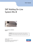
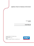
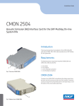
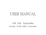
@ptitude Observer
On-line Device Configurator
Part No. 32170800
Revision J
User Manual
Copyright © 2013 by SKF Reliability Systems
All rights reserved.
Aurorum 30, 977 75 Luleå
Sweden
Telephone: +46 (0)31 337 10 00, Fax: +46 (0)920 134 40
SKF Reliability Systems
SKF Condition Monitoring Center
Aurorum 30
977 75 Luleå
Sweden
Telephone: +46 (0)31 337 10 00
FAX: +46 (0)920 134 40
For technical support, contact:
[email protected]
for customers in Europe, Middle East and Africa.
Telephone: +46 (0)31 337 6500
or
[email protected]
for customers in North America, South America and Asia.
Telephone: +1 800 523 7514
Telephone in Latin America: +55 11 4448 8620
Visit us at our web site
www.skf.com/cm
® SKF is a registered trademark of the SKF Group
Table of Contents
Introduction
1-4
CM Network Configuration File
2-5
Creating
....................................................................................................2 - 5
Downloading ....................................................................................................2 - 7
Serial Interface
3-8
....................................................................................................3
-8
Getting Started
by Attaching Cable
....................................................................................................3 - 9
Start Serial Interface
- 10
Serial.........................................................................................................3
Interface for IMx or MasCon16 (CM)
.........................................................................................................3
- 12
TSI Serial
Interface for IMx-R
- 13
Serial.........................................................................................................3
Interface for IMx-M Protection
- 14
Select.........................................................................................................3
COM Port for IMx-M
IMx-R TSI Firmware Download
4 - 17
....................................................................................................4
- 17
Firmware Version
1.0.0 or 1.1.0
....................................................................................................4
- 20
Firmware Version
1.2.0
....................................................................................................4
- 24
Firmware Version
1.3.0 or Later Version
IMx-R Unit TSI Configuration
5 - 28
....................................................................................................5
- 28
With Firmware
Version 1.0.0 or 1.1.0
....................................................................................................5
- 32
With Firmware
Version 1.2.0
....................................................................................................5
- 36
With Firmware
Version 1.3.0 or Later Version
IMx-M Protection Firmware
Download
6 - 40
IMx-M Unit Protection
Configuration
7 - 43
@ptitude Observer On-line Device Configurator
User Manual, Revision J
TOC-3
Introduction
1
Introduction
The @ptitude Observer On-line Device Configurator allows the user to perform all kinds
of operations against SKF MasCon16 and IMx systems. This includes all types of on-line
devices including WindCon, MasCon16R, IMx-R and IMx-M.
This tool is the only way to set the network configuration and identification for the
on-line device. You can also view what the on-line device is measuring right now, clear
measurement data and show current measurement configuration.
1-4
@ptitude Observer On-line Device Configurator
User Manual, Revision J
CM Network Configuration File
2
CM Network Configuration File
A network configuration file is a file that needs to be loaded into the on-line device in
order to make the on-line device a part of the network. It sets an identity on the on-line
device so that @ptitude Observer Monitor knows with which on-line device it is
communicating. This file is basically a text file with the extension .M16 or .IMx.
The file has to be created through @ptitude Observer On-line Device Configurator
and downloaded with the integrated serial interface to the on-line device.
Creating
Creating a configuration file with @ptitude Observer On-line Device Configurator is
simple.
1.
First start the @ptitude Observer x.x On-line Device Configurator program
located in the SKF @ptitude Monitoring Suite.
Figure 2-1: Observer On-line Device Configurator main screen
2.
From the main menu, Click on the icon of Create a network and ID configuration
file for IMx or MasCon16 and save to disk.
@ptitude Observer On-line Device Configurator
User Manual, Revision J
2-5
CM Network Configuration File
Creating
Figure 2-2: Create IMx/MaxCon16 Config screen
·
Device type is the type of unit for which you are about to create a network and
ID configuration file.
·
Configure by defines how the IP address and unit ID of the unit are to be
configured. It can be done by DIP Switches on the main board of the
IMx/MasCon16 unit or by software.
Note that IMx-R units are configured by Software only.
·
2-6
-
Hardware Switches means that the on-line device shall retrieve its device
number from the hex retary switches located on the circuit board of the
unit. The hex rotary switches have to be set manually. For more
information about this, refer to Network Configuration section of the
corresponding user manual, such as IMx-W User Manual, IMx-S User
Manual, etc.
-
Software means that the on-line device shall retrieve its device number
generated by the software.
Device number is required when you select "Configured by Software" option. It
is the unique identifier required to make @ptitude Observer Monitor
communicate with the on-line device.
@ptitude Observer On-line Device Configurator
User Manual, Revision J
CM Network Configuration File
Creating
The valid device number is between 1 and 255. It is important that this device
number must be unique. There can not be two on-line devices with the same
unit number.
·
Obtain an IP address automatically allows the system to get the IP address.
·
Use the following IP address allows the user to enter IP Number, Subnet
mask, and Gateway information manually.
-
IP number and Subnet mask are the standard settings for all devices
communicating with the TCP/IP protocol. Therefore, configure IP number
and subnet mask according to the TCP/IP standard.
Use the "+1" button to increase IP number and Device number by one
when configuring by "Software". This can be useful when configuring a
large number of units by Software.
·
Gateway should be configured according to the TCP/IP standard. If no
gateway should be used, set it to the default value of 0.0.0.0.
@ Observer Monitor IP and @ Observer Monitor Port are the IP number and
port number of the computer where @ptitude Observer Monitor has been
installed.
The on-line device needs to know where the server application is located in
order to send and retrieve data.
·
Ethernet factory defaults interface sets all the values back to the default
values.
·
Save prompts you about the location where you want to save the configuration
file before it begins to save all the changes made. You can save the file
anywhere on your local hard drive.
The configuration file has the extension of .M16 or .IMx, and is used to update
the network configuration of the unit via serial interface.
Downloading
Downloading is a simple one-time process which is accomplished by the serial interface.
Refer to the next section, Serial Interface.
@ptitude Observer On-line Device Configurator
User Manual, Revision J
2-7
Serial Interface
3
Serial Interface
The serial interface in @ptitude Observer On-line Device Configurator contains
functions and instructions that are useful when configuring and performing a service on
on-line devices. This feature is recommended to be run from a portable computer along
with a standard serial cable.
Getting Started by Attaching Cable
Attaching a cable to an on-line device is different depending on the type of the unit and
function. Select the corresponding case and follow the instruction listed from below;
·
For WindCon, open the casing and attach the first end of the serial cable to the
COM port connector. This cable has only one possible place to be attached,
therefore it can not be connected incorrectly.
·
For MasCon16R, connect the first end of the serial cable to the J5 RS 232 port.
Connect the other end to a free COM port on your computer.
·
For IMx-M, connect the SKF USB Isolator cable to a free USB port of your PC.
Connect the other end to the IMx-M unit's USB port. IMx-M has two different
USB ports.
-
USB port for configuration of CM part, located on the front panel of CPU
card.
-
USB port for configuration of Protection part, located on the front panel of
I/O card.
Important - SKF USB isolator cables must always be used when connecting to
IMx-M USB ports.
·
·
For IMx-R, connect the first end of the serial cable to the RS 232 port for TSI
or to the RS 232 port for CM depending on which serial interface will be
performed. Connect the other end to a free COM port on your computer.
-
RS 232 port for CM part (J7 RS232 CM) configuration, located on the
front panel of the unit.
-
RS 232 port for TSI part (J6 RS232 TSI) configuration, located on the
front panel of the unit.
For other IMx, connect the first end of the serial cable to the RS 232 port.
Connect the other end to a free COM port on your computer.
Important - Before going out to do a service or installation in the field, make sure that
your computer actually has a COM port. On some of the new portable computers, the
COM port has been removed and replaced by a USB port. If this is the case, you will need
a "USB to serial converter".
3-8
@ptitude Observer On-line Device Configurator
User Manual, Revision J
Serial Interface
Start Serial Interface
Start Serial Interface
Figure 3-3: Observer On-line Device Configurator main screen
For Condition Monitoring (CM) part of IMx, MasCon 16, IMx-R or IMx-M serial
interface, start @ptitude Observer On-line Device Configurator and click on the icon of
Start serial interface for IMX or MasCon 16.
For IMx-R TSI part serial interface, start @ptitude Observer On-line Device
Configurator and click on the icon of Start IMx-R TSI serial interface.
For IMx-M Protection part serial interface, start @ptitude Observer On-line Device
Configurator and click on the icon of Start IMx-M protection serial interface.
@ptitude Observer On-line Device Configurator
User Manual, Revision J
3-9
Serial Interface
Start Serial Interface
Serial Interface for IMx or MasCon16 (CM)
This section describes the serial interface for Condition Monitoring part of IMx and
MasCon16 units.
All the commands or instructions you can send with the serial interface have equivalent
text commands which you can enter manually, if desired.
Figure 3-4: Serial interface for IMx/MasCon16 screen
·
Select COM port indicates serial port interface for communication.
For IMx-M, refer to Select COM Port for IMx-M in order to find out COM port
number or to change COM port number.
·
Clear clears the output window.
·
Lock is a toggle button which locks/unlocks the contents on the output display
window. This can be useful when a user wants to copy and paste information
from the output window.
·
Remove data deletes all the measurement data and event log that the On-line
Device has collected and stored in the memory.
This command is reasonable to execute just after an installation of an on-line
device. During the installation, a lot of data may have been collected to the
on-line device while connecting sensors or the machinery has not been
running. As a general rule, always run this after finishing an installation to
make sure that incorrect data or data that were taken under wrong conditions
are removed.
3-10
@ptitude Observer On-line Device Configurator
User Manual, Revision J
Serial Interface
Start Serial Interface
·
Update network config. updates the on-line device firmware or send any
other configuration file to the on-line device. These configuration files most
commonly have the extension of .M16 or .IMx. It prompts the user for a
configuration file to download.
·
Syntax Help gives the user access to syntax help in the current prompt.
It is a good practice to use this interface before you start downloading any files
to ensure that you have established communication with the on-line device.
If you don't get the access to syntax help, change the COM port and try it again.
If it still fails, reset the on-line device with RESET command on the physical
on-line device, and repeat the procedure once more.
When you receive the syntax help, the on-line device is ready to be updated.
·
Set debug On/Off prints/not prints measurement values of which the on-line
device is currently measuring, for example, > PROCESS 69.617386 ANA10000004 on channel 4, DBID = 10000004.
·
RESET performs a software reset.
·
Show Config displays the current measurement configuration of which the
on-line device is currently using.
·
Get Events stores all events from the unit to a file in user readable format.
See corresponding IMx user manual for detailed event information.
·
Adv. debug modes (advanced debug modes) should only be used by
experienced installation engineers in cooperation with SKF Condition
Monitoring Center.
·
Command is where you can enter commands or instructions manually.
@ptitude Observer On-line Device Configurator
User Manual, Revision J
3-11
Serial Interface
Start Serial Interface
TSI Serial Interface for IMx-R
Figure 3-5: TSI Serial interface for IMx-R screen
3-12
·
Select COM port indicates serial port interface for communication. Refer to Getting
Started by Attaching Cable in Serial Interface section for IMx-R unit TSI RS 232
port for TSI configuration.
·
Clear clears the output window.
·
Lock is a toggle button which locks/unlocks the contents on the output display
window. This can be useful if a user wants to copy and paste information from the
output window.
·
Command is where you can enter commands or instructions manually. More
information on IMx-R TSI commands can be found in IMx-R User Manual.
·
ASCII row pause in milliseconds is the pause between each ASCII row. Normally
there is no need to change.
·
Get Config reads back the configuration file currently in use by the unit.
·
Update Config downloads a configuration file to IMx-R unit. Refer to IMx-R Unit TSI
Configuration.
·
Update Firmware downloads TSI firmware to IMx-R unit. Refer to IMx-R TSI
Firmware Download.
·
Close closes the TSI Serial Interface for IMx-R screen.
@ptitude Observer On-line Device Configurator
User Manual, Revision J
Serial Interface
Start Serial Interface
Serial Interface for IMx-M Protection
Figure 3-6: TSI Serial interface for IMx-M screen
·
Select COM port indicates serial port interface for communication. Refer to
Getting Started by Attaching Cable in Serial Interface section for IMx-M unit
USB port for IMx-M Protection part configuration.
Refer to Select COM Port for IMx-M in order to find out the COM port number
or to change COM port number.
·
Clear clears the output window.
·
Lock is a toggle button which locks/unlocks the contents on the output display
window. This can be useful if a user wants to copy and paste information from
the output window.
·
Command is where you can enter commands or instructions manually. More
information on IMx-M Protection commands can be found in IMx-M User
Manual.
·
ASCII row pause (in milliseconds) is the pause between each ASCII row.
Normally there is no need to change.
·
Get Config reads back the configuration file currently in use by the IMx-M unit.
·
Update Config downloads a configuration file to IMx-M unit. refer to IM-M Unit
Protection Configuration.
·
Update Firmware downloads protection firmware to IMx-M unit. Refer to
IMx-M Protection Firmware Download.
·
CF displays all the circuit faults (along with descriptions) of the current slot.
·
Close closes the Serial Interface for IMx-M Protection screen.
·
Adv. debug modes (Advanced debug modes) should only be used by
experienced installation engineers in cooperation with SKF Condition
Monitoring Center.
@ptitude Observer On-line Device Configurator
User Manual, Revision J
3-13
Serial Interface
Start Serial Interface
·
Capture to disk saves responses or messages you get from commands and
interfaces to a disk, if checked.
Select COM Port for IMx-M
How to Find Windows Allocated COM Port Number
·
Open Control Panel window and select System.
·
Select Hardware, then Device Manager.
·
Double click on Parts (COM &LPT) to see the available USB Serial Port as
shown in Figure 3-7, below.
Figure 3-7: COM port device manager
3-14
@ptitude Observer On-line Device Configurator
User Manual, Revision J
Serial Interface
Start Serial Interface
How to Change COM Port Number
·
Continue from the above steps.
·
Double click on USB Serial Port, then select Port Settings option.
Figure 3-8: Example of COM port settings
·
Select Advanced... and change the COM Port Number.
@ptitude Observer On-line Device Configurator
User Manual, Revision J
3-15
Serial Interface
Start Serial Interface
Figure 3-9: Example of COM port advanced settings
·
3-16
COM port number can be changed to any COM port number above 2. Ensure
that the port is not in use by any other hardware installed in the computer.
@ptitude Observer On-line Device Configurator
User Manual, Revision J
IMx-R TSI Firmware Download
4
IMx-R TSI Firmware Download
This section guides you how to download TSI firmware to IMx-R units. There are
different instructions depending on the firmware version.
Firmware Version 1.0.0 or 1.1.0
The following steps will guide you with downloading a new firmware version 1.0.0 or
1.1.0 to an IMx-R unit.
1.
Connect IMx-R to a computer by using a null modem cable. A "USB to RS 232
converter" may be required. Refer to Getting Started by Attaching Cable in Serial
Interface section for IMx-R TSI part connection.
2.
Start "Observer On-line Device Configurator 8.3.0" or earlier version and click on
"Start IMx-R TSI serial interface". Refer to TSI Serial Interface for IMx-R.
3.
To download firmware, the IMx-R unit needs to be powered up. If the unit has not
powered up already, power up the IMx-R unit.
Figure 4-10: Example of boot-up text of IMx-R with firmware version 1.0.0 or 1.1.0
4.
The IMx-R displays a version and other text on the RS 232 TSI serial port upon
boot-up. The exact boot-up text depends on the firmware version. Continue to the
next step when the IMx-R is powered up.
@ptitude Observer On-line Device Configurator
User Manual, Revision J
4-17
IMx-R TSI Firmware Download
Firmware Version 1.0.0 or 1.1.0
5.
The default value 30 of “ASCII row pause in Milliseconds” does not need to be
changed.
Figure 4-11: Example of a start transmission of firmware version 1.0.0 or 1.1.0
4-18
6.
Enter "download" in lower case in the Command text box and finish with the Enter
key. The unit writes out its version, in this case "Jul 6 2009 11:38:18".
7.
The unit will ask for the start of the firmware file transmission. Click on “Send file”
button. A dialog for opening a file will appear.
8.
Find a .mot firmware file that you wish to download and open it.
9.
The transmission of the firmware file will start immediately and will be busy for 3
minutes (with 30 ms row pause). Wait for the completion even if the program
appears to be unresponsive.
@ptitude Observer On-line Device Configurator
User Manual, Revision J
IMx-R TSI Firmware Download
Firmware Version 1.0.0 or 1.1.0
Figure 4-12: Example of a successful download of firmware version 1.0.0 or 1.1.0
10. If the download is successful, the unit will reboot and run the new version of
firmware.
11. If an error occurs, retry the procedure.
@ptitude Observer On-line Device Configurator
User Manual, Revision J
4-19
IMx-R TSI Firmware Download
Firmware Version 1.2.0
Firmware Version 1.2.0
The following steps will guide you with downloading a new firmware version 1.2.0 to an
IMx-R unit.
1.
Connect IMx-R to a computer by using a null modem cable. A "USB to RS 232
converter" may be required. Refer to Getting Started by Attaching Cable in Serial
Interface section for IMx-R TSI part connection.
2.
Start "Observer on-line device configurator 8.4.0" and click on "Start IMx-R TSI
serial interface". Refer to TSI Serial Interface for IMx-R.
3.
To download firmware, the IMx-R unit needs to be powered up. If the unit has not
powered up already, power up the IMx-R unit.
Figure 4-13: Example of boot-up text of IMx-R with firmware version 1.2.0
4-20
4.
The IMx-R displays a version and other text on the RS 232 TSI serial port upon
boot-up. The exact boot-up text depends on the firmware version. Continue to the
next step when the IMx-R is powered up.
5.
Click Download Firmware. A dialog for opening a file will appear.
@ptitude Observer On-line Device Configurator
User Manual, Revision J
IMx-R TSI Firmware Download
Firmware Version 1.2.0
Figure 4-14: Example of open file dialog screen for firmware version 1.2.0
6.
Find a .mot firmware file that you wish to download and open it. The password for
the dialog is "secret".
@ptitude Observer On-line Device Configurator
User Manual, Revision J
4-21
IMx-R TSI Firmware Download
Firmware Version 1.2.0
Figure 4-15: Example of download firmware version 1.2.0
7.
4-22
The transmission of the firmware file will start immediately. Wait for the
completion.
@ptitude Observer On-line Device Configurator
User Manual, Revision J
IMx-R TSI Firmware Download
Firmware Version 1.2.0
Figure 4-16: Example of a successful download firmware version 1.2.0
8.
If the download is successful, the unit will reboot and run the new version of
firmware.
@ptitude Observer On-line Device Configurator
User Manual, Revision J
4-23
IMx-R TSI Firmware Download
Firmware Version 1.3.0 or Later Version
Firmware Version 1.3.0 or Later Version
The following steps will guide you with downloading a new firmware version 1.3.0 or
later version to an IMx-R unit.
1.
Connect IMx-R to a computer by using a null modem cable. A "USB to RS 232
converter" may be required. Refer to Getting Started by Attaching Cable in Serial
Interface section for IMx-R TSI part connection.
2.
Start "Observer on-line device configurator 8.4.0c" or later version and click on
"Start IMx-R TSI serial interface". Refer to TSI Serial Interface for IMx-R.
3.
To download firmware, the IMx-R unit needs to be powered up. If the unit is not
powered up already, power up the IMx-R unit.
Figure 4-17: Example of boot-up text of IMx-R with firmware version 1.3.0
4-24
4.
The IMx-R displays a version and other text on the RS 232 TSI serial port upon
boot-up. The exact boot-up text depends on the firmware version. Continue to the
next step when the IMx-R is powered up.
5.
Click Download Firmware. A dialog for opening a file will appear.
@ptitude Observer On-line Device Configurator
User Manual, Revision J
IMx-R TSI Firmware Download
Firmware Version 1.3.0 or Later Version
Figure 4-18: Example of open file dialog screen for firmware version 1.3.0
6.
Find a .mot firmware file that you wish to download and open it. The password for
the dialog is "secret".
@ptitude Observer On-line Device Configurator
User Manual, Revision J
4-25
IMx-R TSI Firmware Download
Firmware Version 1.3.0 or Later Version
Figure 4-19: Example of Download firmware version 1.3.0
7.
4-26
The transmission of the firmware file will start immediately. Wait for the
completion.
@ptitude Observer On-line Device Configurator
User Manual, Revision J
IMx-R TSI Firmware Download
Firmware Version 1.3.0 or Later Version
Figure 4-20: Example of a successful download firmware version 1.3.0
8.
If the download is successful, the unit will reboot and run the new version of
firmware.
@ptitude Observer On-line Device Configurator
User Manual, Revision J
4-27
IMx-R Unit TSI Configuration
5
IMx-R Unit TSI Configuration
The IMx-R unit TSI configuration process varies depending on the firmware version.
With Firmware Version 1.0.0 or 1.1.0
The following steps will guide you how to configure TSI for IMx-R units with the
firmware version 1.0.0 or 1.1.0..
1.
Connect IMx-R to a computer by using a null modem cable. A "USB to RS 232
converter" may be required. Refer to Getting Started by Attaching Cable in Serial
Interface section for IMx-R TSI part connection .
2.
Start Observer on-line device Configurator 8.3.0 or earlier version.
3.
Click on Start IMx-R TSI serial interface. Refer to TSI Serial Interface for IMx-R.
4.
It is strongly recommended to shut down all the running tasks before proceeding
with the TSI configuration of an IMx-R unit.
5.
To configure an IMx-R unit, the unit needs to be powered up. If the IMx-R has not
powered up already, power up the IMx-R.
Figure 5-21: Example of boot-up text of an IMx-R unit with firmware 1.0.0
6.
5-28
The IMx-R displays a version and other text on the RS 232 TSI serial port upon
boot-up. The exact boot-up text depends on the firmware version.
@ptitude Observer On-line Device Configurator
User Manual, Revision J
IMx-R Unit TSI Configuration
With Firmware Version 1.0.0 or 1.1.0
7.
The default value 30 of “ASCII row pause in Milliseconds” does not need to be
changed.
8.
Enter "config" in lower case, in the Command text box and finish with the Enter key.
9.
The unit will ask for a TSI configuration file. Click Send file button. A dialog for
opening files will appear.
Figure 5-22: Example of IMx-R TSI configuration file selection screen
10. Choose a .Bin file with which you wish to configure the unit.
@ptitude Observer On-line Device Configurator
User Manual, Revision J
5-29
IMx-R Unit TSI Configuration
With Firmware Version 1.0.0 or 1.1.0
Figure 5-23: Example of configuration file transmission with IMx-R firmware 1.0.0
11. The transmission of the TSI configuration file will start immediately.
5-30
@ptitude Observer On-line Device Configurator
User Manual, Revision J
IMx-R Unit TSI Configuration
With Firmware Version 1.0.0 or 1.1.0
Figure 5-24: Example of a successful configuration file transmission with IMx-R firmware 1.0.0
12. If the download is successful, the unit will restart with the new TSI configuration.
Make sure to check the TSI configuration information.
@ptitude Observer On-line Device Configurator
User Manual, Revision J
5-31
IMx-R Unit TSI Configuration
With Firmware Version 1.2.0
With Firmware Version 1.2.0
The following steps will guide you how to configure TSI for IMx-R units with the
firmware version 1.2.0.
1.
Connect IMx-R to a computer by using a null modem cable. A "USB to RS 232
converter" may be required. Refer to Getting Started by Attaching Cable in Serial
Interface section for IMx-R TSI part connection.
2.
Start Observer on-line device Configurator 8.4.0.
3.
Click on Start IMx-R TSI serial interface. Refer to TSI Serial Interface for IMx-R.
4.
It is strongly recommended to shut down all the running tasks before proceeding
with the configuration of an IMx-R.
5.
To configure an IMx-R unit, the unit needs to be powered up. If the IMx-R is not
powered up already, power up the IMx-R.
Figure 5-25: Example of boot-up text of an IMx-R unit with firmware 1.2.0
5-32
6.
The IMx-R displays a version and other text on the RS 232 TSI serial port upon
boot-up. The exact boot-up text depends on the firmware version.
7.
Enter "config" in lower case in the Command text box and finish with the Enter key.
8.
Click on Download config button. A dialog for opening files will appear.
@ptitude Observer On-line Device Configurator
User Manual, Revision J
IMx-R Unit TSI Configuration
With Firmware Version 1.2.0
Figure 5-26: Example of configuration file selection screen with IMx-R firmware 1.2.0
9.
Choose a .Bin file with which you wish to configure the unit.
@ptitude Observer On-line Device Configurator
User Manual, Revision J
5-33
IMx-R Unit TSI Configuration
With Firmware Version 1.2.0
Figure 5-27: Example of configuration file transmission with firmware 1.2.0
10. The transmission of the TSI configuration file will start immediately.
5-34
@ptitude Observer On-line Device Configurator
User Manual, Revision J
IMx-R Unit TSI Configuration
With Firmware Version 1.2.0
Figure 5-28: Example of a successful configuration file transmission with IMx-R firmware 1.2.0
11. If the download is successful, the unit will restart with the new TSI configuration.
Make sure to check the TIS configuration information.
@ptitude Observer On-line Device Configurator
User Manual, Revision J
5-35
IMx-R Unit TSI Configuration
With Firmware Version 1.3.0 or Later Version
With Firmware Version 1.3.0 or Later Version
The following steps will guide you how to configure TSI for IMx-R units with the
firmware version 1.3.0.
1.
Connect IMx-R to a computer by using a null modem cable. A "USB to RS 232
converter" may be required. Refer to Getting Started by Attaching Cable in Serial
Interface section for IMx-R TSI part connection.
2.
Start Observer on-line device Configurator 8.4.0c or later version.
3.
Click on Start IMx-R TSI serial interface. Refer to TSI Serial Interface for IMx-R.
4.
It is strongly recommended to shut down all the running tasks before proceeding
with the configuration of an IMx-R unit.
5.
To configure an IMx-R unit, the unit needs to be powered up. If the IMx-R is not
powered up already, power up the IMx-R unit.
Figure 5-29: Example of boot-up text of an IMx-R unit with firmware 1.3.0
5-36
6.
The IMx-R displays a version and other text on the RS 232 TSI serial port upon
boot-up. The exact boot-up text depends on the firmware version.
7.
Click on Download config button.
8.
The password for the dialog is "secret". A dialog for opening files will appear.
@ptitude Observer On-line Device Configurator
User Manual, Revision J
IMx-R Unit TSI Configuration
With Firmware Version 1.3.0 or Later Version
Figure 5-30: Example of configuration file selection screen with IMx-R firmware 1.3.0
9.
Choose a .Bin file with which you wish to configure the unit.
@ptitude Observer On-line Device Configurator
User Manual, Revision J
5-37
IMx-R Unit TSI Configuration
With Firmware Version 1.3.0 or Later Version
Figure 5-31: Example of configuration file transmission with IMx-R firmware 1.3.0
10. The transmission of the TSI configuration file will start immediately.
5-38
@ptitude Observer On-line Device Configurator
User Manual, Revision J
IMx-R Unit TSI Configuration
With Firmware Version 1.3.0 or Later Version
Figure 5-32: Example of a successful configuration file transmission with IMx-R firmware 1.3.0
11. If the download is successful, the unit will restart with the new TSI configuration.
Make sure to check the TSI configuration information.
@ptitude Observer On-line Device Configurator
User Manual, Revision J
5-39
IMx-M Protection Firmware Download
6
IMx-M Protection Firmware Download
The following steps will guide you with downloading a new firmware to an IMx-M unit.
1.
Connect IMx-M to a computer by using a SKF USB Isolator cable. Refer to Getting
Started by Attaching Cable in Serial Interface section for IMx-M Protection part
connection.
2.
Start "Observer on-line device configurator 9.0.0" or later version and click on
Start IMx-M protection serial interface. Refer to Serial Interface for IMx-M
Protection.
3.
To download firmware, the IMx-M unit needs to be powered up and must be in
disarm mode.
Important - System must be in disarm mode before Protection firmware update
procedure takes place. Ensure to read "Protection Firmware Update" chapter in
IMx-M User Manual thoroughly and understand it.
Figure 6-33: Example of boot-up text of an IMx-M unit
4.
The IMx-M displays a version and other text on the USB port upon boot-up. The
exact boot-up text depends on the firmware version.
Continue to the next step when the IMx-M is powered up.
5.
Depending on which firmware version you have in the system, or to which firmware
version you will be updating, you can either select the button "Update Firmware"
(faster) or enable debug mode and select the button "3. Update firmware Adv.".
If you are not sure whether the change of firmware requires an advanced firmware
update or not, always choose "3. Update firmware Adv.".
6.
6-40
A dialog for opening a file will appear.
@ptitude Observer On-line Device Configurator
User Manual, Revision J
IMx-M Protection Firmware Download
Figure 6-34: Example of update firmware file selection screen for IMx-M
7.
Find a .a48 firmware file that you wish to download and open it. The password for
the dialog is "secret".
Figure 6-35: Example of update firmware for IMx-M
8.
The transmission of the firmware file will start immediately. Wait for the
completion.
@ptitude Observer On-line Device Configurator
User Manual, Revision J
6-41
IMx-M Protection Firmware Download
Figure 6-36: Example of a successful update firmware for IMx-M
9.
When download is successfully completed, then the unit will reboot and run the new
version of the firmware.
Important - Disarm must not be released until the unit is running with a proper
firmware. Ensure to read "Protection Firmware Update" chapter in IMx-M User
Manual thoroughly and understand it.
6-42
@ptitude Observer On-line Device Configurator
User Manual, Revision J
IMx-M Unit Protection Configuration
7
IMx-M Unit Protection Configuration
This section guides you how to download Protection part configuration to an IMx-M unit.
1.
Connect IMx-M to a computer by using a SKF USB Isolator cable. Refer to Getting
Started by Attaching Cable in Serial Interface section for IMx-M Protection part
connection.
2.
Start Observer On-line Device Configurator 9.0.0 or later version.
3.
Click on Start IMx-M protection serial interface. Refer to Serial Interface for
IMx-M Protection.
4.
To configure an IMx-M unit, the unit needs to be powered up and must be in disarm
mode.
Important - System must be in disarm mode before Protection configuration update
procedure takes place. Ensure to read "Protection Configuration Update" chapter in
IMx-M User Manual thoroughly and understand it.
Figure 7-37: Example of boot-up text of IMx-M unit
5.
The IMx-M displays a version and other text on the USB port upon boot-up. The
exact boot-up text depends on the firmware version.
6.
Click on Update Config button. The password for the dialog is "secret". A dialog for
opening files will appear.
@ptitude Observer On-line Device Configurator
User Manual, Revision J
7-43
IMx-M Unit Protection Configuration
Figure 7-38: Example of configuration file selection screen for IMx-M
7.
Choose a .Bin file with which you wish to configure the IMx-M unit.
Figure 7-39: Example of configuration file transmission for IMx-M
8.
7-44
The transmission of the configuration file will start immediately.
@ptitude Observer On-line Device Configurator
User Manual, Revision J
IMx-M Unit Protection Configuration
Figure 7-40: Example of a successful configuration file transmission for IMx-M
9.
If the download is successful, the unit will restart with the new IMx-M Protection
part configuration.
ü
Ensure to read and understand "Disarm" chapter in IMx-M user manual before
disarm is released.
ü
Ensure there are no circuit faults before disarmed is released.
ü
Wait at least 30 seconds before you release disarm.
@ptitude Observer On-line Device Configurator
User Manual, Revision J
7-45