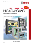
1
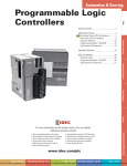
HG3G
Operator Interface
New Operator Interface. Brightest in Its Class.
Sharper. Brighter. More colorful!
Stylish design in dark or light gray bezel.
Dark Gray
Light Gray
8.4-inch
10.4-inch
cd/m2
cd/m2
o
s
n
e
e
b
r
ve
e
n
s
a
h
e
c
a
f
r
e
t
n
nd
i
a
r
,
o
y
t
s
a
a
r
e
e
,
p
ed
e
p
An o
s
h
g
i
h
id,
v
i
v
d
n
a
sharp
simple!
HG3G
Operator Interface
HG3G Operator Interface 8.4 inch
2
Industrial Equipment
Dust resistant
HG3G can be used as an information terminal in various applications such as production lines. An optional UV surface protection
sheet is available.
IP66
Information Device
Bright and sharp display
HG3G can be used as a reception or booking
display. Bright and vivid, these screens are easy
to use and view. The sleek design is suitable for
a wide range of applications.
Peripheral Device
Outstanding functionality
HG3G is extremely functional as a screen
ordering system. Excellent connectivity with
peripheral devices and high-speed processing ensures outstanding operation of many
applications.
3
LED
Brightest in its class.* True-to-life color. High resolution.
* Based on IDEC research as of July 2010
Backlight
Brightest
in the Market!
Energy-saving design with
LED backlight
50% less energy than conventional model of HG3F with 450
cd/m2 brightness (when USB
and IO are not connected)
00 cd/m2
6
(8.4-inch)
700 cd/m2
(10.4-inch)
High
Resolution
SVGA
65,536
colors
High-quality
color
reproduction
32-scale
dimming
TFT
Screen size: 8.4 or 10.4 inch
Dimensions: 231 × 176 × 54.4 mm (8.4 inch), 270 × 212 × 52.7 mm (10.4 inch)
Bezel:
Dark gray or light gray
Sharp and Vivid
Backlight
Extremely bright LED backlight
Bright LED backlight provides a vivid
display even in well-lit surroundings.
(8.4-inch: 600 cd/m2, 10.4-inch: 700 cd/m2)
screens even in bright surroundings.
The combination of LED backlight and
dimming function achieves the desired
brightness. Long 60,000-hour service life.
High-resolution SVGA and
Display 65,536-color display
Graphics
1,000 graphic images have been
added. Realistic images of
switches, pilot lights, and other
parts allow you to easily create
your own custom screens.
Fonts
With a high resolution (800 × 600 pixels),
the SVGA LCD clearly shows small
characters and thin lines. Plus true-to-life
colors can be reproducted with vibrant
clarity.
Sharper, clearer
alpha-numeric characters
By using the stroke and
7-segment fonts, large numeric
characters can be created,
improving long distance
visibility.
∗ The screen images on this brochure are simulated pictures.
4
More than 7,000
graphic images
Sharp images.
Instant
Response
RISC 400MHz CPU
USB2.0 480Mbps
Fast start-up
High Speed
CPU
Fast start-up, quick operation
High-speed 400 MHz CPU and unique
software technology shorten the startup
time after power-on. Fast start-up allows
for easy debugging.
3-sec startup
(Note)
Note: When using a standard screen image used by IDEC.
Standard Font
Stroke Font
USB
Fast USB2.0 communication
Project data can be downloaded and
uploaded easily using a USB flash drive,
allowing for easy debugging and also saving
time and money.
7-segment
Font
5
Simple Operation
Easy
Maintenance
USB
Startup
Menu
USB
Passthrough
Large
capacity
32GB
(SDHC)
Easy
USB
USB flash drive allows for easy
data transfer.
Inserting a USB flash drive into the HG3G
will automatically bring up the USB
transfer menu. Operator can work on
errors without the use of PC.
Execution Confirmation
Line A data transfer
Line D data transfer
Line B data transfer
Line E data transfer
Line C data transfer
Cancel
Press to select a production line to transfer the
graphic data onto the screen.
Call XXX-XXX in the event of error.
Easy data maintenance, without
Mainte- opening the control cabinet.
nance
Using the USB panel-mount cable, data
can be transferred without opening the
panel. The pass-through function enables
debugging of ladder programs in the PLC,
connected to the HG3G, inside the
cabinet.
See “Compatible PLCs” on page 12.
6
USB Memory or PC
SD
Card
Convenient SD card slot
Data from the HG3G can be
saved or transferred by using
an SD card (32GB max.).
Project data, picture data,
data log data, alarm log data,
screenshot data, recipe data,
operation log data, audio files,
and MicroSmart ladder
programs can all be stored on
an SD card.
I/O module
Add I/O modules
(64 I/O max.)
Simple
I/O Control
Power input terminal block (24V DC)
Terminal block (COM2)
RS232C/485 (422)
D-sub 9 pins (COM1)
RS232C/485 (422)
SD card
USB-A
Audio output
MicroSmart
USB-miniB (PC connection)
Digital I/O
Expansion module
installed on the back
Ethernet
Simple Control
Switch
Sensor
Lamp
Simple Connection
I/O
Display and I/O control in one reduces
labor time.
Module A maximum of two MicroSmart expansion
Ethernet
Connection
I/O modules can be connected to one HG3G,
allowing for equipment control using a small
number of I/O points with easy I/O control
(input, output, I/O module can be used.)
* See “Compatible I/O Modules” on page 12.
O/I Link IDEC high-speed 115.2 kbps
Communication
O/I Link communication.
A maximum of 16 HG3Gs can be
connected to a PLC using RS485 (2-wire),
easily creating a high-speed network
reducing costs and labor.
Master
Slave 1
Audio
Output
Remote data maintenance
Project data can be downloaded and
uploaded to the HG3G remotely via
Ethernet. One HG3G can
communicate with two or more PLCs,
enabling the integration of network
(PC) and the control network (PLC)
systems.
Sound file (30 sec. max.)
Audio error messages can be sent to
the operator, providing faster system
recovery. Audio ouput can be used as
a voice guidance sytem to improve
productivity.
Ethernet
PLC
PLC
Speaker
Slave 2
Slave 2
Host
O / I Link
Slave
15 max.
7
Buzzer
HG3G Operator Interface
Excellent visibility achieved by super-bright LED backlight.
600 cd/m2 (8.4-inch), 700 cd/m2 (10.4-inch)
• High-resolution SVGA (800 × 600 pixels) and 65,536 colors provides
high-quality display.
• Combination of LED backlight and dimming function allows for the best
brightness, while assuring a long service life (60,000 hours minimum).
• High-speed 400 MHz CPU and IDEC's unique software technology
achieve fast start-up and speed of operation.
• USB and Ethernet ports on all models.
• IDEC's high-speed 115.2 kbps O/I link communication.
• More than 7,000 graphic images available in the image library. Various
images such as switches and pilot lights allow you to create your own
screen.
• Stroke font and 7-segment font. Large character numbers can be
displayed clearly.
• USB2.0 allows you to download/upload project data from USB memory.
• Auto-start menu of USB flash drive enables easy transfer of project
and historical data.
• Use of USB panel-mount cable lets you work on data maintenance
directly, without opening the control cabinet.
• A maximum of two expansion MicroSmart I/O modules can be mounted, making it possible to control small equipment, with a small number
of I/O points, and also to perform simple I/O control.
10.4-inch (light gray)
8.4-inch (dark gray)
(Approval for HG3G operator interface only,
excluding options or expansion modules.)
Types
Display Screen
8.4-inch TFT color LCD
65,536 colors
10.4-inch TFT color LCD
65,536 colors
Operation Type
Touch Switch
(analog resistive)
Interface
••Options
Name
Housing/Bezel Color
COM1 [RS232C/485 (422)]
COM2 [RS232C/485 (422)]
LAN [10 Base-T/100 Base-TX]
AUDIO OUT [LINE OUT]
USB1 [USB2.0 Device]
USB2 [USB2.0 Host]
SD [SD Memory Card]
Type No.
Ordering Type No.
Package
Quantity
Type No.
Light gray
HG3G-8JT22TF-W
Dark gray
HG3G-8JT22TF-B
Light gray
HG3G-AJT22TF-W
Dark gray
HG3G-AJT22TF-B
Remarks
CE
UL
c-UL
Description
SW1A-W1C
1
USB Maintenance Cable (2m)
HG9Z-XCM42
PLC Connection Cable
HG9Z-XC295
For IDEC MicroSmart (5m)
PLC Connection Cable
HG9Z-XC305
For Mitsubishi FX series (5m)
PLC Connection Cable
HG9Z-XC315
For Mitsubishi Q series (5m)
PLC Connection Cable
HG9Z-XC275
For IDEC MicroSmart (5m)
PLC Connection Cable
FC2A-KP1C
For IDEC MicroSmart (2.4m)
USB panel-mount extension cable (1m) HG9Z-XCE11
HG9Z-XCM42
1
Complete package includes Wind CFG system configuration
software, WindLDR PLC programming software, and
WindO/I-NV2 OI Touchscreen programming software.
PDF files of English/Japanese/Chinese manuals are stored
on the CD.
USB Cable USB-miniB
HG9Z-XC295
1
Mini DIN 8-pin (Dsub 9-pin)
HG9Z-XC305
1
Mini DIN 8-pin (Dsub 9-pin)
HG9Z-XC315
1
Mini DIN 6-pin (Dsub 9-pin)
HG9Z-XC275
1
Mini DIN 8-pin (loose wire)
FC2A-KP1C
1
Mini DIN 8-pin (loose wire)
HG9Z-XCE11
1
For USB-A port
USB panel-mount extension cable (1m)
HG9Z-XCE21
HG9Z-XCE21
1
Connector Conversion Cable (16cm)
HG9Z-XCT11
HG9Z-XCT11
1
Memory Card
HG9Z-XMS2
HG9Z-XMS2
1
For USB-mini B port
To convert from D-sub 25-pin to 9-pin
(used when replacing from HG3F/4F to HG3G)
SD Memory Card (2GB)
HG9Z-3D8
HG9Z-3D8PN02
2
For HG3G 8.4-inch.
HG9Z-3DA2
HG9Z-3DA2PN02
2
HG9Z-XJ1
HG9Z-XJ1PN05
5
HG9Z-XJ2
HG9Z-XJ2PN05
5
L-shaped Terminal Block Connector for
I/O Module (Note 3)
HG9Z-PMT10L
HG9Z-PMT10LPN02
2
For HG3G 10.4-inch.
For installing the expansion modules on the back of the
HG3G (short). For total width 17.6 to 41.1mm.
For installing the expansion modules on the back of the
HG3G (long). For total width 47.0 to 68.8mm.
For MicroSmart I/O Module (10-pole)
HG9Z-PMT11L
HG9Z-PMT11LPN02
2
For MicroSmart I/O Module (11-pole)
Manual “WindO/I-NV2”
HG9Y-B1119
HG9Y-B1119
1
English
Application Software “Automation Organizer” (CD)
(English/Japanese/Chinese)
Protective Sheet (Note 1)
Expansion Module Clamp (Note 2)
SW1A-W1C
Note 1:The protective sheet is UV resistant, however, resistance against direct sunlight in outdoor usage is not guaranteed.
Note 2:Use the expansion module bracket when using expansion modules. Choose HG9Z-XJ1 (short) or HG9Z-XJ2 (long) referring to the width of modules shown
on the next page.
+
or
+ .
Use XG9Z-XJ1 (short) when using any one module of
, or when using two modules in the combination of
Use XG9Z-XJ2 (long) when using two modules in the combination of
+ ,
+ ,
+ ,
+ ,
+ ,
+ , or
+ . (Combination of
+
is
not possible).
Note 3:See Cat No. EP1203 or instruction manual for expansion modules of MicroSmart.
8
HG3G Operator Interface
••Maintenance Parts
Name
Type No.
Ordering Type
No.
Package
Quantity
Mounting Clip
HG9Z-4K2
HG9Z-4K2PN04
4
Host Communication Plug
HG9Z-XT09
HG9Z-XT09
1
Replacement Battery
HG9Z-XR1
HG9Z-XR1
1
USB Cable Lock Pin
HG9Z-XU1
HG9Z-XU1PN05
5
Description
Four clips are supplied with HG3G.
One plug (terminal block type) is supplied with
HG3G.
Lithium battery CR2032
(one battery is supplied with HG3G)
Used to lock USB cable (for USB2).
••Input Modules
Input Type
Type No.
  8 points/DC Input
FC4A-N08B1
16 points/DC Input
FC4A-N16B1
16 points/DC Input
FC4A-N16B3
32 points/DC Input
FC4A-N32B3
  8 points/AC Input
FC4A-N08A11
Connector
Removable Terminal Block
MIL Connector
Removable Terminal Block
Dimensions (L × W × H mm)
90.0 × 23.5 × 70.0
90.0 × 23.5 × 70.0
90.0 × 17.6 × 70.0
90.0 × 29.7 × 70.0
90.0 × 23.5 × 70.0
••Output Modules
Output Type
Type No.
Connector
Dimensions (L × W × H mm)
90.0 × 23.5 × 70.0
  8 points/Relay Output
FC4A-R081
16 points/Relay Output
FC4A-R161
  8 points/Transistor Sink Output
FC4A-T08K1
  8 points/Transistor Source Output
FC4A-T08S1
90.0 × 23.5 × 70.0
16 points/Transistor Sink Output
FC4A-T16K3
90.0 × 17.6 × 70.0
16 points/Transistor Source Output
FC4A-T16S3
32 points/Transistor Sink Output
FC4A-T32K3
32 points/Transistor Source Output
FC4A-T32S3
Removable Terminal Block
MIL Connector
90.0 × 23.5 × 70.0
90.0 × 23.5 × 70.0
90.0 × 17.6 × 70.0
90.0 × 29.7 × 70.0
90.0 × 29.7 × 70.0
••Mixed I/O Modules
I/O Type
  4 points/DC Input
  4 points/Relay Output
16 points/DC Input
  8 points/Relay Output
Type No.
Connector
Dimensions (L × W × H mm)
FC4A-M08BR1
Removable Terminal Block
90.0 × 23.5 × 70.0
FC4A-M24BR2
Non-removable Terminal Block
90.0 × 39.1 × 70.0
• Use the expansion module bracket when using expansion modules. Choose HG9Z-XJ1 (short) or HG9Z-XJ2 (long) referring to the width of modules shown above.
Use XG9Z-XJ1 (short) when using any one module of
, or when using two modules in the combination of + or + .
Use XG9Z-XJ2 (long) when using two modules in the combination of + , + , + , + , + , + , or + .
(Combination of + is not possible).
• See Cat No. EP1203 or instruction manual for expansion modules of MicroSmart.
9
HG3G Operator Interface
General Specifications
Rated Power Voltage
Power Voltage Range
Power Consumption
Allowable Momentary
Power Interruption
Inrush Current
Dielectric Strength
Insulation Resistance
Operating Temperature
Operating Humidity
Storage Temperature
Storage Humidity
Pollution Degree
Vibration Resistance
Shock Resistance
Noise Immunity
Electrostatic Discharge
Corrosion Immunity
Mounting
Degree of Protection
Dimensions
Weight (approx.)
24V DC
20.4 to 28.8V DC
25W maximum
15W maximum when not using USB interface
(USB2) or expansion module interface (EXT)
10 ms maximum
30A maximum
1000V AC, 10 mA, 1 minute between power and
FG terminals
10 MΩ minimum between power and FG terminals (500V DC megger)
0 to +50°C
10 to 90% RH (no condensation)
−20 to +60°C
10 to 90% RH (no condensation)
2
5 to 9 Hz amplitude 3.5 mm,
9 to 150 Hz, acceleration 9.8 m/s2
10 cycles (100 minutes) on each of three mutually perpendicular axes
147 m/s2, 11 ms
5 shocks on each of three mutually perpendicular
axes
Fast transient/burst test,
Power terminals: ±2 kV, Communication line: ±1
kV (IEC 61131-2: 2007)
Contact ±6 kV, air ±8 kV
(IEC 61131-2: 2007)
Free from corrosive gases
Panel mounting
IP66
HG3G-8: 231.0W × 176.0H × 54.4D mm
HG3G-A:270.0W × 212.0H × 52.7D mm
HG3G-8: 1.25 kg
HG3G-A:1.65 kg
• Do not use the HG3G in an environment subject to strong ultraviolet rays, otherwise the LCD quality will deteriorate.
General Specifications
Switching Element
Operating Force
Mechanical Life
Acknowledgement
Sound
Analog resistive membrane
0.55 to 2.3N
1,000,000 operations
Display Specifications
Display Color
Color/Shade
TFT Color LCD
65,536 colors
HG3G-8: 170.4W × 127.8H mm
Effective Display Area
HG3G-A: 211.2W × 158.4H mm
Display Resolution
800W × 600H pixels
View Angle
Right and left 80°, up 80°, down 60°
Backlight
LED
Backlight Life
60,000 hours minimum (Note)
Brightness
HG3G-8: 600 cd/m2, HG3G-A: 700 cd/m2
Brightness Adjustment
32 scales
Backlight Replacement Impossible (by IDEC only)
8 × 8 pixels (Western European language: ISO
8859-1, Central European language: ANSI 1250,
1/4 size
Baltic: ANSI 1257, Cyrillic: ANSI1251, Japanese
katakana and symbols: JIS 8-bit code)
8 × 16 pixels (Western European language ISO
8859-1, Central European language: ANSI 1250,
Baltic: ANSI 1257, Cyrillic: ANSI1251, Japanese
1/2 size
katakana and symbols: JIS 8-bit code)
Display
16 × 32 pixels, 24 × 48 pixels, 32 × 64 pixels
Character
(Western European language: ISO 8859-1)
Size
16 × 16 pixels (Japanese JIS first and second level
Full size
characters, simplified Chinese, traditional Chinese,
Korean)
32 × 32 pixels
Double size
(Japanese JIS first level characters, Mincho font)
Width 8 to 128 dots (1/2 size fixed)
Scalable
(ISO 8859-1 western language, 7-segment)
1/4 size
100 characters × 75 lines
Quantity of 1/2 size
100 characters × 37 lines
CharacFull size
50 characters × 37 lines
ters
Double size 25 characters × 18 lines
0.5, 1, 2, 3, 4, and 8 vertically and horizontally
Character Magnification
(except for scalable fonts)
Blink (1 or 0.5 sec period), reverse, bold,
Character Attribute
shadowed
Straight line, polyline, rectangle, circle, ellipse, arc,
Graphics Type
pie, equilateral polygons (3, 4, 5, 6, 8), paint, bitmap
image
Window Display
3 popup screens + 1 system screen
Note:The backlight life refers to the time until the surface brightness reduces by
half after continuous use at room temperatures.
Interface Specifications
Electrical
Characteristics
Electronic buzzer or speaker output
Function Specifications
Base screen, sub screen, system screen
screen:3000 max.
No. of Screens Base
Sub screen: 3015 max.
User Memory
12 MB (including expansion fonts)
Bit Button, Word Button, Goto Screen, Print Button, Key
Button, Multi Button, Keypad, Selector Switch, Potentiometer, Numerical Input, Character Input, Pilot Lamp, MultiState Lamp, Picture Display, Message Display, Message
Parts
Switching Display, Alarm List Display, Alarm Log Display,
Numerical Display, Bar Graph, Trend Chart, Pie Chart,
Meter, Calendar, Bit Write Command, Word Write Command, Goto Screen Command, Print Command, Screen
Script Command, Multi Command, Timer
Year, Month, Day, Hour, Min., Sec., Day of Week
Calendar
±60 sec per month (at 25 °C)
Power Failure Calendar, log data, keep internal relay, keep internal
Backup Data
register
Battery Life
4 years (at 25°C) (1-year warranty)
Serial Interface
(COM1)
Screen Types
Serial Interface
(COM2)
Ethernet
Interface
(LAN)
Audio Interface
USB Interface
(USB2)
USB Interface
(USB1)
Memory Card
Interface (SD)
Transmission Speed
Synchronization
Communication
Method
Control System
Connector
Electrical
Characteristics
Transmission Speed
Synchronization
Communication
Method
Control System
Connector
Interface
EIA RS232C/485 (422) compliant
1200, 2400, 4800, 9600, 19200,
38400, 57600, 115200, 187500 bps
(Note)
Asynchronous
Half or full duplex
Hardware control or none
D-sub 9-pin connector
EIA RS232C/485 (422) compliant
1200, 2400, 4800, 9600, 19200,
38400, 57600, 115200, 187500 bps
(Note)
Asynchronous
Half or full duplex
Hardware control or none
Detachable 9-pin terminal block
IEEE802.3 (10/100BASE-T) compliant
Connector
Modular connector (RJ-45)
Interface
Connector
Interface
Connector
Interface
Connector
Interface
Connector
LINE OUT (stereo)
Mini Jack connector (ø3.5 mm)
USB 2.0 high speed (480 Mbps)
USB Type A connector
USB 2.0 high speed (480 Mbps)
USB Type Mini-B connector
SD memory card, SDHC memory card
SD memory card socket
Expansion
Module Inter- Interface
face (EXT)
MicroSmart I/O Unit
Note:187500 bps is available only with SIEMENS SIMATIC S7-300 series
(MPI port direct connection).
10
HG3G Operator Interface
Dimensions
32.6
•HG3G-8 (8.4-inch)
21.0
219.0 +2.0
0
12.4
176.0
163.5
164.0 +2.0
0
Panel thickness
2.0 to 5.0
231.0
48.4
54.4
38.2
6.0
218.5
Panel thickness
2.0 to 5.0
50.2
0
258.0 +2.0
12.4
199.5
212.0
270.0
200.0 +2.0
0
30.9
•HG3G-A (10.4-inch)
46.7
52.7
All dimensions in mm.
36.5
6.0
257.5
30.9
Panel Cut-out
•HG3G-8
(8.4-inch)
Panel thickness
2.0 to 5.0
•HG3G-A (10.4-inch)
50.2
0
258.0 +2.0
200.0 +2.0
0
199.5
12.4
12.4
164.0
+2.0
0
219.0 +2.0
0
36.5
6.0
46.7
52.7
• Install the HG3G into a panel cut-out by tightening the four mounting clips
(supplied with the HG3G) to a torque of 0.3 to 0.4 N·m (HG3G-8) and 0.5
to 0.6 N·m (HG3G-A).
Note:Do not tighten with excessive force, otherwise the HG3G and screen
will be distorted. Also waterproof characteristics may be lost.
All dimensions in mm.
11
Compatible PLCs
Manufacturer
Series
OpenNet
Controller
MicroSmart
IDEC
MicroSmart
Pentra
MELSEC-A
MELSEC-QnA
Mitsubishi
MELSEC-Q
MELSEC-FX
SYSMAC-C
OMRON
CPU
Connection
√
√
√
√
A2CCPUC24
A0J2, A0J2H, A2A, A3A, A2U,
A3U, A4U, A2US, A2USH-S1
Q4ACPU, Q4ARCPU,
Q3ACPU, Q2ACPU,
Q2ACPU-S1
Q2ASHCPU, Q2ASHCPU-S1,
Q2ASCPU, Q2ASCPU-S1
Q00CPU, Q01CPU
√
√
√
√
√
√
√
Panasonic
FP series
KOSTAC SU
√
√
√
√
√
√
√
CPM2A
√
√
√
√
√
√
√
√
√
Link
Unit
Ethernet
√
√
√
√
√
√
√
√
SU-6H
√
SU-5E, SU-6B
√
√
√
•Ethernet link unit may be necessary for some PLCs.
•The company names and product names are registered trademarks or brand names.
•The compatible PLC information is for reference only (except for IDEC PLCs), and IDEC
does not guarantee the operation of any other manufacturers’ PLC. When using other
manufacturers’ PLCs, read their specifications and instruction manual carefully. The PLC
must be operated correctly under the user’s responsibility.
The updated information of the compatible PLCs can be found at the
following website.
http://www.IDEC.com/oi/drivers
Automation Organizer
√
O/I Touchscreen Programming
Software Ver. 4.∗
√
Useful functions allow you to create and test programs easily and quickly.
State view and monitoring functions reduce programming work
√
√
SYSMAC-CP
CP1H
PLC-5
PLC-5, PLC-5E
Screen Image
√
√
√
√
SLC5/03, SLC5/04
√
√
SLC5/05
MicroLogix1000
MicroLogix1100
MicroLogix1200
MicroLogix1500
ControlLogix5550
ControlLogix5555
1768CompactLogix
√
√
√
√
1769CompactLogix
√
1794-L33, 1794-L34
√
Green lamp ON
Red lamp ON
√
Screen/project list
Safety Precautions
CPU
Connection
SU-5M, SU-6M
√
FX3UC, FX3U, FX3G
C500, C500F, C1000H,
C1000HF, C2000, C2000H,
C200HS, C200HE, C200HG,
C200HX, C120, C120F
C20H, C28H, C40H, C60H,
CQM1H,
C200HS-CPU21/23/31/33,
C200HE-CPU42,
C200HG-CPU43/63,
C200HX-CPU44/64
CPM1, CPM1A
KV-700, KV-1000
TWDLCAA16DRF
TWDLCAA24DRF
171CCC96020
FP0, FP10, FP10SH, FP1,
FP2, FP2SH, FP∑
SZ-4
KOSTAC SZ
√
√
CPU212, CPU214,
CPU215, CPU216,
CPU221, CPU222,
CPU224, CPU226
CPU224XP, CPU226XM
CPU313C-2PtP
Modicon
Modbus
√
Q02CPU, Q02HCPU
Q06HCPU, Q12PHCPU,
Q25HCPU
Q00JCPU
FX0, FX0N, FX1, FX2, FX2C,
FX-0S, FX-1S
FX2N, FX2NC, FX1N, FX1NC
Applicable CPU Unit
S7-200
KV-700, KV-1000
Schneider Twido
Modicon Momentum
Momentum
Koyo
√
Series
S7-300
√
√
FlexLogix
SIEMENS
√
√
CS1G, CS1H
CompactLogix
√
Manufacturer
Keyence
CJ1M, CJ1H, CJ1G
ControlLogix
Ethernet
FC3A-CP2
SYSMAC-CS1
MicroLogix
Link
Unit
FC4A-C10R2
FC4A-C16R2/C24R2,
FC4A-D20K3/D20S3,
FC4A-D20RK1/D20RS1,
FC4A-D40K3/D40S3
FC5A-C10R2/C16R2,
FC5A-C24R2,
FC5A-C10R2C/C16R2C,
FC5A-C24R2C
FC5A-D16RK1/D16RS1
FC5A-D32K3/D32S3
A1N, A2N, A3N, A1SH
SYSMAC-CJ
SLC-500
AllenBradley
Applicable CPU Unit
Objects list
Parts list
Read the safety precautions described in the user's manual to confirm correct operation of the HG3G.
Specifications and other descriptions in this catalog are subject to change without notice.
7-31, Nishi-Miyahara 1-Chome, Yodogawa-ku, Osaka 532-8550, Japan
Tel: +81-6-6398-2571, Fax: +81-6-6392-9731
E-mail: [email protected]
IDEC CORPORATION (USA)
Wendenstrasse 331, 20537 Hamburg, Germany
Tel: +49-40-25 30 54 - 0, Fax: +49-40-25 30 54 - 24
E-mail: [email protected]
IDEC CANADA LIMITED
Room 608-609, 6F, Gangtai Plaza, No. 700,
Yan'an East Road, Shanghai 200001, PRC
Tel: +86-21-5353-1000, Fax: +86-21-5353-1263
E-mail: [email protected]
3155 Pepper Mill Court, Unit 4, Mississauga,
Ontario, L5L 4X7, Canada
Tel: +1-905-890-8561, Toll Free: (888) 317-4332
Fax: +1-905-890-8562
E-mail: [email protected]
IDEC AUSTRALIA PTY. LTD.
2/3 Macro Court, Rowville, Victoria 3178, Australia
Tel: +61-3-9763-3244, Toll Free: 1800-68-4332
Fax: +61-3-9763-3255
E-mail: [email protected]
IDEC ELECTRONICS LIMITED
www.idec.com
IDEC ELEKTROTECHNIK GmbH
1175 Elko Drive, Sunnyvale, CA 94089-2209, USA
Tel: +1-408-747-0550 / (800) 262-IDEC (4332)
Fax: +1-408-744-9055 / (800) 635-6246
E-mail: [email protected]
Unit 2, Beechwood, Chineham Business Park,
Basingstoke, Hampshire RG24 8WA, UK
Tel: +44-1256-321000, Fax: +44-1256-327755
E-mail: [email protected]
IDEC (SHANGHAI) CORPORATION
IDEC (BEIJING) CORPORATION
Room 211B, Tower B, The Grand Pacific Building,
8A Guanghua Road, Chaoyang District,
Beijing 100026, PRC
Tel: +86-10-6581-6131, Fax: +86-10-6581-5119
IDEC (SHENZHEN) CORPORATION
Unit AB-3B2, Tian Xiang Building, Tian’an Cyber Park,
Fu Tian District, Shenzhen, Guang Dong 518040, PRC
Tel: +86-755-8356-2977, Fax: +86-755-8356-2944
IDEC IZUMI (H.K.) CO., LTD.
Units 11-15, Level 27, Tower 1,
Millennium City 1, 388 Kwun Tong Road,
Kwun Tong, Kowloon, Hong Kong
Tel: +852-2803-8989, Fax: +852-2565-0171
E-mail: [email protected]
IDEC TAIWAN CORPORATION
8F-1, No. 79, Hsin Tai Wu Road, Sec. 1,
Hsi-Chih, Taipei County, Taiwan
Tel: +886-2-2698-3929, Fax: +886-2-2698-3931
E-mail: [email protected]
IDEC IZUMI ASIA PTE. LTD.
No. 31, Tannery Lane #05-01,
HB Centre 2, Singapore 347788
Tel: +65-6746-1155, Fax: +65-6844-5995
E-mail: [email protected]
Cat. No. EP1358-0 AUGUST 2010 2.9S PRINTED IN JAPAN