1
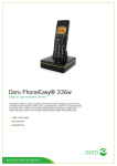
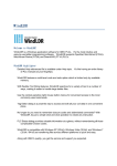
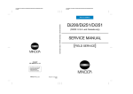
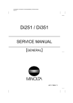
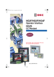
All-in-one touchscreen interface and logic controller FT1A Touch Key Features • 3.8” HMI+PLC • Models with 12 or 14 I/O • Embedded RJ45 Ethernet Port • Modbus TCP or RTU • Built-in 2 analog inputs • Built-in 2 analog outputs • Optional Analog Cartridges • PID Controls • USB Maintenance Port • Seamless interface with other PLCs • Class 1 Div. 2 Hazardous Locations • -20 to 55 degree C operating temp. • IP66f, Nema 4X (indoor), 13 The FT1A SmartAXIS Touch combines operator interface and control in a single compact package, all programmable with IDEC’s PC-based software. The FT1A Touch is available in 12 I/O and 14 I/O configurations with analog I/O expansion capability suitable for advanced analog monitoring and control. General Specifications Part No. FT1A-*12RA-* FT1A-*14KA-* / FT1A-*14SA-* Output Relay output Transistor output Rated Power Voltage/ Power Supply Isolation 24V DC/Not isolated Allowable Voltage Range 20.4 to 28.8V DC (including ripple) Power Consumption 9.2 W maximum Allowable Momentary Power Interruption 10 ms maximum Dielectric Strength Between power terminal and FE terminal: 500V AC, 5 mA, 1 minute Between power terminal and output terminal: 2,300V AC, 5 mA, 1 minute EMC Immunity IEC/EN 61131-2:2007 compliant Inrush Current 50A maximum (5ms maximum) Operating Temperature Color display: –20 to +55°C, Monochrome display: 0 to +55°C (Note 1) (Note 2) Storage Temperature –20 to +60°C (no freezing) Relative Humidity 10 to 95% RH (no condensation) Pollution Degree 2 (IEC 60664-1) Corrosion Immunity Atmosphere free from corrosive gases Degree of Protection IP66F TYPE 4X TYPE 13 (Panel front) (Note 3), IP20 (Rear) Ground Functional grounding Protective grounding conductor UL1007 AWG16 Shock Resistance 5 to 8.4 Hz half amplitude 3.5 mm, 8.4 to 150 Hz, acceleration 9.8 m/s2 (1G), 2 hours per axis on each of three mutually perpendicular axis (IEC 61131-2) 147 m/s2, 11 ms, X, Y, Z directions 3 times (IEC 61131-2) Mounting Structure Panel mount Weight (approx.) 300g Vibration Resistance 11W maximum Between power terminal and FE terminal: 500V AC, 5 mA, 1 minute Between power terminal and output terminal: 500V AC, 5 mA, 1 minute 250g Note 1: FT1A-*12RA-* hardware version V130 (indicated on hardware) and earlier is UL, c-UL listed at 50°C (maximum operating temperature). Note 2: See SmartAXIS Touch User’s Manual FT9Y-B1390(2) for I/O derating. Note 3: Operation not guaranteed when used with certain types of oils. Function Specifications FT1A-*12RA-* Stored program system Ladder Program Part Number Control System Instruction Words Basic Instructions 42 types Advanced Instructions 98 types Program Capacity Processing Time 99 types Basic Instruction 1850μs/1,000 steps END Processing 5 msec minimum 37 types Program Capacity Program size: 38kB, Configuration memory capacity: 5MB FB (Note 1) No. of FB 1,000 Timer (T) 200 Counter (C) Processing Time 200 Basic Instruction 4ms/100 END Processing 5ms minimum User Program Storage I/O Points Flash ROM (100,000 times) 8 (V3.90 or above: 90 max. can be added with remote I/O master function) 4 (V3.90 or above: 54 max. can be added with remote I/O master function) 2 (V3.90 or above: 24 max. can be added with remote I/O master function) — Inputs Outputs Analog Input Analog Output 8 (90 max. can be added with remote I/O master function) 4 (54 max. can be added with remote I/O master function) 2 (4 max. can be added with analog cartridge, and 24 max. can be added with remote master function) 2 (4 max. can be added with analog cartridge) Internal Relays 1,024 Shift Registers 128 Data Registers 2000 Special Data Registers 200 Counters 200 Timer (1ms, 10 ms, 100 ms, 1s) 200 RAM Backup Clock Precision: ±30 seconds/month (25°C, typical) Backup Data Internal relays, shift registers, counters, data registers, clock data Backup Duration Approximately 30 days (typical) at 25°C after backup battery is fully charged Battery Lithium secondary battery Charging Time Approximately 15 hours required to charge from 0 to 90% Replaceability Not possible Keep data check, power failure check, watchdog timer check,timer/counter preset value change error check, user program syntax check, user program execution check No filter, 3 to 15 ms (selectable in increments of 1 ms) Self-Diagnostic Functions Input Filter Catch Input/Interrupt Input High-speed Counter FT1A-*14SA-* Program size: 47.4 kB, Configuration memory capacity: 5 MB FB FBD FT1A-*14KA-* 4/4 Single/two-phase selectable Maximum Counting Frequency and Points 1 (5 kHz, multiple 2/4, single-phase cannot be used) Single-phase 4 (x 10 kHz) Counting Range 0 to 4,294,967,295 (32 bits) Operation Mode Rotary encoder mode and adding counter mode Built-in Points Analog Voltage Inputs 2 Input Range 0 to 10V DC 0 to 10V DC (voltage input) /4 to 20 mA (current input) Input Impedance 78 kΩ 78 kΩ (voltage input) / 250 Ω (current input) Digital Resolution 0 to 1,000 (10 bits) Number of Relay Outputs 10A relay: 4 Number of Transistor Outputs Analog Output — — 4 (sink) Built-in Points — 2 4 (source) Output Range — 0 to 10V DC (voltage output) /4 to 20 mA (current output) Digital Resolution — 0 to 1,000 (10 bits) USB-mini B (Note 2) USB-A (Note 2) RS232C (Note 2) RS485/422 (Note 2) Ethernet Expansion Communication Ports Port 2 — Port 3 — Memory Cartridge — SD Memory Card Analog Cartridge Interface — Number of Ports — 2 Connectable Cards — 4 (FC6A-PJ2A, FC6A-PK2AV, FC6A-PK2AW, FC6A-PJ2CP) Note 1: Except for timer, counter, input FB, and output FB. Note 2: Not isolated from internal circuits. Display Specifications Touch Display Element TFT color LCD STN monochrome LCD Colors/Shades 65,536 colors Monochrome 8 shades Effective Display Area 88.92 W x 37.05 H mm 87.59 W x 35.49 H mm Display Resolution 240 W x 100 H pixels View Angle Left/right 40°, top 20°, bottom 60° Left/right/top/bottom: 45° Contrast Adjustment Not possible 32 levels Backlight LED LED (white, red, pink) Backlight Life 50,000 hours (Note 1) Brightness 400 cd/m2 (Note 2) Brightness Adjustment 32 levels Backlight Control Auto off function Backlight Replacement Not possible No. of Characters Display Character Size Part No. 1/4 Size 740 cd/m2 (Note 2) 8 x 8 pixels [JIS 8-bit code, ISO 8859-1 (Western European languages), ANSI 1250 (central Europe)], ANSI 1257 (Baltic), ANSI 1251 (Cyrillic) 8 x 16 pixels [JIS 8-bit code, ISO 8859-1 (Western European languages), ANSI 1250 (central Europe) ], ANSI 1257 (Baltic), ANSI 1251 (Cyrillic) 1/2 Size 16 x 32 pixels, 24 x 48 pixels, 32 x 64 pixels (Western European languages: ISO 8859-1) Full Size 16 x 16 pixels (Japanese JIS first and second level characters, simplified Chinese, traditional Chinese, Korean) Double Size 32 x 32 pixels (Japanese JIS first level characters, Mincho font) 1/4 Size 30 characters x 12 lines/screen 1/2 Size 30 characters x 6 lines/screen Full Size 15 characters x 6 lines/screen Double Size 7 characters x 3 lines/screen Character Magnification 0.5x, 1x, 2x, 3x, 4x, 5x, 6x, 7x, 8x vertically and horizontally Character Attributes Blink, reverse, bold, shadowed (blink is 1 sec or 0.5 sec) Graphics Line, polyline, polygon, rectangle, circle, ellipse, arc, pie, equilateral polygons (3, 4, 5, 6, 8), fill, picture Window Display 3 popup screens + 1 system screen Note 1: The backlight life refers to the time until the brightness reduces by half after use at 25°C. Note 2: Brightness of LCD only (monochrome LCD: when lit white). Operation Specifications Part No. Touch Switching Element Analog resistive membrane (touch panel) Operating Force 0.2 to 2.5N Mechanical Life 1 million operations Acknowledgment Sound Electric Buzzer Multiple Press Not possible HMI Function Specifications Functions Drawings, bit button, word button, goto screen button, key button, multi-button, keypad, selector switch, potentiometer, numerical input, character input, pilot lamp, picture display, message display, message switching display, alarm list display, alarm log display, numerical display, bar chart, line chart, pie chart, meter, calendar, bit write command, word write command, goto screen command, timer, script command, multi-command, system area, start time, Auto Backlight OFF, O/I Link, user communication, maintenance communication, DM Link Communication, PLC Link Communication (Note 1), alarm log, data log, operation log, data storage area, preventive maintenance, recipe, text group, global script, user account, project data transfer using external memory, downloading logged data in external memory, USB auto-run function Note 1: The up-to-date information on the connectable PLC can be obtained from http://www.idec.com/language. Input Specifications *12RA-* Part Number Digital Input *14SA-* Source Sink Input Points 6 Input Type Sink Input Voltage Range 0 to 28.8V DC Rated Input Current 4.4 mA 5.2 mA 4.4 mA Input Impedance 5.5 kΩ 4.7 kΩ 5.5 kΩ Input Delay Time Isolation OFF ON 2.5 μs + soft filter setting ON OFF 5 μs + soft filter setting Between input terminals Not isolated Internal circuit Not isolated Input Type Type 1 (IEC 61131-2) External Load for I/O Interconnection Not needed OFF voltage Sink type: 5V DC max. Source type: 15V DC min. ON voltage Sink type: 15V DC min. Source type: 5V DC max. OFF current Sink type: 0.9 mA max. Source type: –1.0 mA min. ON current Sink type: 2.7 mA min. Source type: –3.0 mA max. Operating Level Analog Input *14KA-* Input Points 2 Input Type Voltage input Voltage/Current input Input Range 0 to 10.0 VDC 0 to 10.0 VDC / 4 to 20 mA Sampling Duration Time 2 ms maximum Total Input System Transfer Time 3 ms + sampling time + scan time Digital Resolution 0 to 1,000 (10 bits) Input Error Isolation 3 ms + sampling time + scan time (voltage input) 12 ms + sampling time + scan time (current input) 25°C ±3% of full scale Total ±5% of full scale Between input terminals Not isolated Internal circuit Not isolated Digital I/O Type 1 (not conforming to IEC 61131-2 digital I/O type) OFF voltage: 5V maximum When used as digital input Operation Level ON voltage: 15V minimum OFF current: 0.06 mA maximum ON current: 0.20 mA minimum External Power for Input Input Voltage Range — Output Current Capacity — Output Specifications *12RA-* *14KA-* *14SA-* Transistor Sink Output 4 — Transistor Source Output — 4 Part Number Output Points Rated Load Voltage 24V DC Input Voltage Range Transistor Output Maximum Load Current 20.4 to 28.8V DC 1 point 0.3A maximum 1 common 1A maximum Voltage Drop (ON Voltage) 1V maximum (voltage between COM and output terminals when output is ON) Inrush Current 1A — Leakage Current 39V ± 1V Maximum Lamp Load 8 W maximum Inductive Load L/R = 10 ms (28.8V DC, 1 Hz) External Current Draw Isolation Output Delay Photocoupler isolated Between output terminals Not isolated OFF ON 100μS max. ON OFF 200μS max. 100,000 operations minimum (resistive load 1,800 operations/h) 20 million operations minimum (no load 18,000 operations/h) Mechanical Life Dielectric Strength 100 mA maximum, 24V DC Between output terminal and internal circuit Electrical Life Relay Output Common 0.1 mA maximum Clamping Voltage — — — — Between output terminal and internal circuit 2,300V AC, 1 minute — — Between output terminals (between COMs) 2,300V AC, 1 minute — — Analog Output Output Points Note 1: Note 2: 2 Analog Output Signal Type Voltage/Current output (Selectable) Analog Output Range 0 to 10V DC / 4 to 20mA Load Impedance 2kΩ min (voltage input) / 500 Ω max (current input) Applicable Load Type Resistive Load Maximum Deviation at 25°C ±0.3% of full scale Temperature Coefficient ±0.02%/°C of full scale Repeatability After Stabilization Time Non-linearity ±0.4% of full scale — ±0.01% of full scale Output Ripple 30mV max. (spike noise not included) Overshoot 0% (Note 2) Total Error ±1.0% of full scale including ripple Effect of Improper Output Connection No damage Digital Resolution 0 to 1,000 (10 bits) Output Value of LSB 10mV (0-10V) / 16μA (4-20mA) Monotonicity Yes Current loop open Not detectable High-speed output terminal (100 kHz pulse output terminal): 5 μs max. Normal output terminal (including 5kHz pulse output terminal): 100 μs max. Overshoot may occur under light load conditions. Overshoot can be suppressed by inserting a damping resistor. Damping resistor value: approx. 150Ω including the input impedance. Analog Expansion Cartridge Specifications (FC6A-P) Specifications FC6A-PJ2CP FC6A-PK2AV FC6A-PK2AW Part No. FC6A-PJ2A Type Voltage/Current Input Temperature Input Voltage Output Current Output 2 2 2 5.0V: 70mA 3.3V: 30mA 5.0V: 185mA 3.3V: 30mA Number of Input/Output 2 Rated Voltage 5.0V, 3.3V (supplied from the Touch) Consumption Current 5.0V: – 3.3V: 30mA Weight 15g Output Specifications Part Number FC6A-PK2AV FC6A-PK2AW Type Voltage Output Current Output Output Type Load D/A Conversion Voltage Output Current Output 2kΩ min. 4 to 20mA DC 500 kΩ max. Load Type Resistance Load Cycle Time 20ms Settling Time 40ms max. 20ms max. Total Output System Transfer Type 60ms+1 scan 40ms+1 scan Maximum Error at 25°C ±0.3% of full scale Temperature Coefficient ±0.02%/°C of full scale Reproducibility after Stabilization Time ±0.4% of full scale Non-linearity ±0.01% of full scale 30mV max. Overshoot 0% Maximum Error ±1.0% of full scale Effect of Improper Output Terminal Connection No damage Digital Resolution 4096 (12 bits) LSB Output Value 2.44mV (0 to 10V) 3.91μA (4 to 20mA) Data Format in Application 0 to 4095 (0 to 10V) 0 to 4095 (4 to 20mA) Monotonicity Yes Open Current Loop Noise Resistance — — Impedance Output error Output Ripple Data 0 to 10V DC — Maximum Temporary Deviation during Electrical Noise Tests ±4.0 of full scale Recommended Cable Shieleded twisted pair Crosstalk 1 LSB max. Isolation None Calibration to Maintain Rated Accuracy Impossible Selection of Output Signal Type Voltage output only Cannot be detected Current output only Applicable Wire Cartridge Part No. FC6A-PJ2A FC6A-PJ2CP FC6A-PK2AV Applicable Wire 0.3mm2 (AWG22) shielded twisted pair 0.3mm2 (AWG22) twisted pair 0.3mm2 (AWG22) shielded twisted pair FC6A-PK2AW Input Specifications Part No. FC6A-PJ2A Input Type Voltage Input FC6A-PJ2CP Current Input Input Range 0 to 10V DC 4 to 20mA DC 0 to 20mA DC Input Impedance 1MΩ min. 250Ω max. Resistance Thermometer Thermocouple Pt100: Pt1000: Ni100: Ni1000: 3-wire RTD K: –200 to 1300°C J: –200 to 1000°C R: 0 to 1760°C S: 0 to 1760°C B: 0 to 1820°C E: –200 to 800°C T: –200 to 400°C N: –200 to 1300°C C: 0 to 2315°C 1MΩ min. –200 to +850°C –200 to +600°C –60 to +180°C –60 to +180°C — 10Ω max. Input Detection Current — Typ: 0.2mA, 1.0mA max. Sample Duration Time — Noise Resistance — 10ms Sample Interval Total Input System Transfer Time Type of Input Single-ended input Operating Mode Self-scan Conversion Method SAR 250ms 20ms 500ms 20ms + 1 scan 500ms + 1 scan Maximum Error at 25°C ±0.1% of full scale Temperature Coefficient ±0.02%/°C of full scale Reproducibility After Stabilization Time ±0.5% of full scale Non-liniarity ±0.01% of full scale Maximum Error ±1.0% of full scale ±0.1% of full scale ±0.1% of full scale Cold junction compensation accuracy ±4.0°C or less Exceptions R, S thermocouple error: ±6.0°C (0 to 200 °C range only) B thermocouple error: Not guaranteed (0 to 300 °C range only) K, J, E, T, N thermocouple error: ±0.4% of full scale (0°C or lower range only) Pt100: Pt1000: Ni100: Ni1000: K: 15,000 (14 bits) J: 12,000 (14 bits) R: 17,600 (15 bits) S: 17,600 (15 bits) B: 18,200 (15 bits) E: 10,000 (14 bits) T: 6,000 (13 bits) N: 15,000 (14 bits) C: 23,150 (15 bits) 10,500 8000 2400 2400 Digital Resolution 4096 (12 bits) LSB Input Value 2.44mV (0 to 10V DC) Data Format in Application Can be arbitrarily set for each channel in the range of –32,768 to 32,773 Monotonicity Yes Maximum Temporary Deviation during Electrical Noise Tests ±4.0% of full scale Recommended Cable Shielded twisted pair Crosstalk 1LSB max. Data Input Error AD Conversion Allowable Conductor Resistance Isolation None Effect When Input is Incorrectly Wired No damage Maximum Allowable Constant Load (non-destructive) 13V DC Input Type Modification Software programming Calibration to Maintain Rated Accuracy Impossible 4.88μA 3.91μA (DC0 to 20mA) (DC4 to 20mA) 0.1°C 0.18°F Twisted pair 40mA 13V DC (14 bits) (13 bits) (12 bits) (12 bits) Mounting Hole Layout Note: Waterproof characteristic may not be obtained depending on the panel material and size. FT1A-*12RA-* FT1A-*14*A-* LCD Active Area X Y TFT 88.92 37.05 STN 87.59 35.49 66.0 +1 0 LCD Type 105.0 +1 0 All dimensions in mm. Dimensions Relay Output Model (FT1A-12RA-∗) When using mounting bracket (HG9Z-4K2PN04) Transistor Output Model (FT1A-14KA-∗ / FT1A-14SA-∗) When using mounting bracket (HG9Z-4K2PN04) All dimensions in mm. Panel thickness: 1.0 to 5.0 (Note) 104.5 When using rear mount adapter (FT9Z-1A01) 4.0 11.8 57.7 65.5 104.5 125.0 2-70.0 4-M3 tapped hole 4.0 11.8 58.9 61.6 4-φ4.0 98.0 105.0 116.0 2-100.0 4-R4.25 4.0 4-ø 97.0 98.0 105.0 tapped hole 54.9 (58.9) 57.6 (61.6) When using rear mount adapter (FT9Z-1A01) 125.0 70.0 4-M3 77.0 90.0 116.0 100.0 4-R 4.25 4.0 X 116.0 2-97.0 53.7 (57.7) 77.0 2-90.0 4.0 X 116.0 77.0 Y 77.0 Y 65.5 Panel thickness: 1.0 to 5.0 (Note) Terminal Arrangement and I/O Wiring Diagram Examples Touch (Display Model) FT1A-∗12RA-∗ + – + – For terminal arrangement and I/O wiring diagram, see User’s Manual. Power Terminal 1 SD 5 SG Port 9 RDB Ry OUT Q0 COM0 Q0 COM0 L DC IN Q0 COM0 L Q0 COM0 L I0 I1 I2 I3 I4 I5 I6 I7 – 2-wire Sensor + L + Analog voltage output device – FT1A-∗14KA-∗ FT1A-∗14SA-∗ + Power Terminal − − − + − + + 1 SD Power Terminal 1 SD 5 SG 5 SG Port DC IN 9 RDB Q0 Q1 Q2 Q3 L L L L AI0 (+) Analog OUT Tr OUT COM (-) V (+) AQ0 (+) + AQ1 (+) AQ0 (-) − Analog voltage/ current input device AQ1 (-) + I0 I1 I2 I3 − I4 I5 AI0 (−) AI1 (+) I6 AI1 (−) DC IN + − Q0 Q1 Q2 Q3 L L L L COM (+) V (-) AQ0 (+) + Analog voltage/ current output device − AI0 (+) Analog OUT Tr OUT I7 + 2-wire Sensor Analog voltage/ current input device Port 9 RDB AQ0 (-) AQ1 (+) AQ1 (-) − + Analog voltage/ current input device I0 I1 − I2 I3 I4 I5 AI1 (+) I6 AI1 (-) I7 + − Analog voltage/ current input device AI0 (-) − Analog voltage/ current output device 2-wire Sensor + Recommended Ferrules for Touch/Pro/Lite Terminals For 2-wire connection L1 d2 d1 L1 S1 d3 L2 S2 S1 d2 d1 L2 S2 For 1-wire connection Touch 1-wire connection 2-wire connection Screwdriver Pro/Lite I/O Cross Section (mm2) AWG Phoenix Contact Part No. 0.25 24 Al0.25-8YE 0.34 22 Al0.34-8TQ 0.5 20 Al0.5-8WH Al0.75-8GY Al1-8RD — Al1-10RD — Al1.5-8BK Al1.5-10BK — Al-TWIN2×0.5-8WH Al-TWIN2×0.75-8GY Al-TWIN2×0.75-10GY — SZS 0.6×3.5 — — SZS 0.4×2.5 — — — 0.75 18 1.0 1.5 16 0.5 20 0.75 18 Power Supply Serial Interface Transistor Output Model L2 d1 S1 d2 12.5 8.0 0.8 0.15 1.8 0.25 12.5 8.0 0.8 0.15 2.0 0.25 14.0 8.0 1.1 0.15 2.5 0.25 14.0 8.0 1.3 0.15 2.8 14.0 8.0 1.5 0.15 3.0 — 16.0 10.0 1.5 0.15 3.0 0.3 — 14.0 8.0 1.8 0.15 3.4 0.3 — 18.0 10.0 1.8 0.15 3.4 — 15.0 8.0 1.5 0.15 2.5 4.6 0.25 15.0 8.0 1.8 0.15 2.8 5.2 0.25 — 17.0 10.0 1.8 0.15 2.8 5.2 0.25 — — — Dimensions in mm. d3 S2 L1 Relay Output Model Power Supply I/O — — — — — 0.25 0.3 0.3 Note: Crimping pliers - Phoenix Contact part number CRIMPFOX ZA3 (12101882) IDEC Corporation • 1175 Elko Drive • Sunnyvale, CA 94089 • 800-262-IDEC (4332) • Fax: 408-745-5258 • www.IDEC.com/usa ©2014 IDEC Corporation. All Rights Reserved.