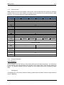
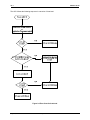
1
User Manual for HE-NX220, HE-NX221, HE-NX222 HE-NX250, HE-NX251, HE-NX252 SmartStack, SmartStix NX OCS MAN0781-05-EN MAN0781-05-EN PREFACE PREFACE This manual explains how to use the NX OCS Modules. Copyright (C) 2006 Horner APG, LLC., 59 South State Avenue, Indianapolis, Indiana 46201. All rights reserved. No part of this publication may be reproduced, transmitted, transcribed, stored in a retrieval system, or translated into any language or computer language, in any form by any means, electronic, mechanical, magnetic, optical, chemical, manual or otherwise, without the prior agreement and written permission of Horner APG, Inc. All software described in this document or media is also copyrighted material subject to the terms and conditions of the Horner Software License Agreement. Information in this document is subject to change without notice and does not represent a commitment on the part of Horner APG. Cscape, SmartStack, SmartStix and CsCAN are trademarks of Horner APG. Ethernet is a trademark of Xerox Corporation. CompactFlash is a registered trademark of SanDisk Corporation. For user manual updates, contact Technical Support: North America: Tel: (+) (317) 916-4274 Fax: (+) (317) 639-4279 Web: www.heapg.com Email: [email protected] Europe: Tel: (+) 353-21-4321-266 Fax: (+) 353-21-4321-826 Web: www.horner-apg.com Email: [email protected] August 20, 2009 Page 3 of 95 ECN # 979 PREFACE MAN0781-05-EN LIMITED WARRANTY AND LIMITATION OF LIABILITY Horner APG,LLC. ("HEAPG") warrants to the original purchaser that the NX OCS module manufactured by HEAPG is free from defects in material and workmanship under normal use and service. The obligation of HEAPG under this warranty shall be limited to the repair or exchange of any part or parts which may prove defective under normal use and service within two (2) years from the date of manufacture or eighteen (18) months from the date of installation by the original purchaser whichever occurs first, such defect to be disclosed to the satisfaction of HEAPG after examination by HEAPG of the allegedly defective part or parts. THIS WARRANTY IS EXPRESSLY IN LIEU OF ALL OTHER WARRANTIES EXPRESSED OR IMPLIED INCLUDING THE WARRANTIES OF MERCHANTABILITY AND FITNESS FOR USE AND OF ALL OTHER OBLIGATIONS OR LIABILITIES AND HEAPG NEITHER ASSUMES, NOR AUTHORIZES ANY OTHER PERSON TO ASSUME FOR HEAPG, ANY OTHER LIABILITY IN CONNECTION WITH THE SALE OF THIS NX OCS module. THIS WARRANTY SHALL NOT APPLY TO THIS NX OCS module OR ANY PART THEREOF WHICH HAS BEEN SUBJECT TO ACCIDENT, NEGLIGENCE, ALTERATION, ABUSE, OR MISUSE. HEAPG MAKES NO WARRANTY WHATSOEVER IN RESPECT TO ACCESSORIES OR PARTS NOT SUPPLIED BY HEAPG. THE TERM "ORIGINAL PURCHASER", AS USED IN THIS WARRANTY, SHALL BE DEEMED TO MEAN THAT PERSON FOR WHOM THE NX OCS module IS ORIGINALLY INSTALLED. THIS WARRANTY SHALL APPLY ONLY WITHIN THE BOUNDARIES OF THE CONTINENTAL UNITED STATES. In no event, whether as a result of breach of contract, warranty, tort (including negligence) or otherwise, shall HEAPG or its suppliers be liable of any special, consequential, incidental or penal damages including, but not limited to, loss of profit or revenues, loss of use of the products or any associated equipment, damage to associated equipment, cost of capital, cost of substitute products, facilities, services or replacement power, down time costs, or claims of original purchaser's customers for such damages. To obtain warranty service, return the product to your distributor with a description of the problem, proof of purchase, post paid, insured and in a suitable package. ABOUT PROGRAMMING EXAMPLES Any example programs and program segments in this manual or provided on accompanying diskettes are included solely for illustrative purposes. Due to the many variables and requirements associated with any particular installation, Horner APG cannot assume responsibility or liability for actual use based on the examples and diagrams. It is the sole responsibility of the system designer utilizing the NX OCS module to appropriately design the end system, to appropriately integrate the NX OCS module and to make safety provisions for the end equipment as is usual and customary in industrial applications as defined in any codes or standards which apply. Note: The programming examples shown in this manual are for illustrative purposes only. Proper machine operation is the sole responsibility of the system integrator. August 20, 2009 Page 4 of 95 ECN # 979 MAN0781-05-EN PREFACE Table of Contents CHAPTER 1 : INTRODUCTION .................................................................................................................. 7 1.1 Scope.............................................................................................................................................. 8 1.2 NX Models ...................................................................................................................................... 8 1.2.1 Product Description ................................................................................................................. 8 1.2.2 Cscape Software ..................................................................................................................... 9 1.3 NX OCS Specifications................................................................................................................. 10 1.4 NX OCS Resources...................................................................................................................... 10 1.4.1 Overview................................................................................................................................ 10 1.4.2 Resource Limits..................................................................................................................... 11 1.4.3 Resource Definitions ............................................................................................................. 11 1.5 References ................................................................................................................................... 17 1.6 Technical Support......................................................................................................................... 18 CHAPTER 2 : INSTALLATION / SAFETY (NX OCS) .............................................................................. 19 2.1 Dimensions and Panel Cut-Out .................................................................................................... 19 2.2 Mounting Requirements ............................................................................................................... 20 2.2.1 Mounting Procedures (Installed in a Panel Door) ................................................................. 20 2.2.2 NX OCS Mounting Clips (Standard and NEMA and IP65 Washdown)................................. 21 2.2.3 NX OCS Mounting Orientation .............................................................................................. 22 2.3 Factors Affecting Panel Layout Design and Clearances .............................................................. 22 2.3.1 Panel Layout Design and Clearance Checklist: .................................................................... 24 2.4 Ports, Connectors, Cables, and Wiring ........................................................................................ 24 2.4.1 Primary Power Port / Grounding ........................................................................................... 24 2.4.2 Primary Power Port ............................................................................................................... 25 2.4.3 CAN Network Port and Wiring...............................................................................................25 2.4.4 RS-232 Port / RS-485 Serial Ports........................................................................................ 29 2.4.5 I/O Port (HSC) ....................................................................................................................... 32 2.4.6 Modem Setup ........................................................................................................................ 32 2.5 NX LEDs ....................................................................................................................................... 33 2.5.1 LEDs...................................................................................................................................... 33 2.6 Battery Replacement .................................................................................................................... 33 2.7 Safety............................................................................................................................................ 35 CHAPTER 3 : CONFIGURATION - SYSTEM MENU (NX)....................................................................... 37 3.1 General ......................................................................................................................................... 37 3.2 Navigating Through the System Menu ......................................................................................... 37 3.3 Editing System Menu Screen Fields............................................................................................. 37 3.4 Initial System Menu Screens and Self-Test ................................................................................. 38 3.5 Entering the System Menu ........................................................................................................... 38 3.6 System Menu Option Screens...................................................................................................... 38 CHAPTER 4 : KEYPAD AND SCREEN.................................................................................................... 45 4.1 Remote Screen and Keypad Capability ....................................................................................... 45 4.1.1 Cscape Status Bar ................................................................................................................ 45 4.1.2 Establishing Communications using the Remote Text Terminal........................................... 46 4.2 NX Description.............................................................................................................................. 46 4.3 User Screens ................................................................................................................................ 47 CHAPTER 5 : SMARTSTACK .................................................................................................................. 49 5.1 General ......................................................................................................................................... 49 5.2 Preliminary Configuration Procedures.......................................................................................... 49 CHAPTER 6 : SMARTSTIX I/O .................................................................................................................. 55 6.1 General ......................................................................................................................................... 55 6.2 SmartStix I/O Introduction ............................................................................................................ 55 6.3 SmartStix I/O Modules.................................................................................................................. 55 August 20, 2009 Page 5 of 95 ECN # 979 PREFACE MAN0781-05-EN 6.4 BASIC SMARTSTIX PROGRAMMING ........................................................................................ 55 6.4.1 Using GET and PUT..............................................................................................................55 6.4.1.1 Get Remote I/O Function Block .........................................................................................55 6.4.1.2 Get Remote Parameter Description: ................................................................................. 56 6.4.1.3 Put Remote I/O Function Block ......................................................................................... 57 6.4.1.4 Put Remote Parameter Description:.................................................................................. 58 6.5 SmartStix I/O Default Operation ................................................................................................... 58 6.6 SmartStix I/O Module Device Classes.......................................................................................... 59 6.7 SmartStix I/O Module Consumed (Received) Directed Data ....................................................... 60 6.8 Consumed Directed Data Power-Up Initialization ........................................................................ 61 6.9 SmartStix I/O Module Produced (Transmitted) Global Data ........................................................ 62 6.10 Produced Global Data Power-Up Initialization.......................................................................... 62 6.11 SmartStix I/O Module LED Indicators .......................................................................................63 6.11.1 Diagnostic LED Indicators ..................................................................................................... 63 6.11.2 Status LED Indicators............................................................................................................ 63 6.12 SmartStix I/O Module Network ID .............................................................................................63 CHAPTER 7 : USING COMPACTFLASH™ MEMORY CARDS............................................................... 65 7.1 General ......................................................................................................................................... 65 7.2 Compact Flash Overview ............................................................................................................. 65 7.2.1 Accessing Files with an NX OCS .......................................................................................... 65 7.2.2 Accessing Files with a PC ..................................................................................................... 65 7.3 CompactFlash Function Blocks in Cscape................................................................................... 65 7.4 Configuring CompactFlash Manager in Cscape........................................................................... 66 7.5 Filenames Used with the CompactFlash Function Blocks ........................................................... 66 7.6 System Registers used with CompactFlash................................................................................. 67 CHAPTER 8 : BUILT-IN HIGH SPEED I/O (HSC / PWM) ........................................................................ 69 8.1 Overview....................................................................................................................................... 69 8.2 Glossary........................................................................................................................................ 69 8.3 I/O Port ......................................................................................................................................... 70 8.4 I/O Specifications.......................................................................................................................... 70 8.5 NX Register Mapping ................................................................................................................... 71 8.5.1 PWM Examples ..................................................................................................................... 71 8.6 Cscape Configuration for HSC / Frequency Measurement .......................................................... 72 8.6.1 Preliminary Configuration Procedures .................................................................................. 72 8.6.2 Configuration Procedures......................................................................................................73 8.6.3 Run-time I/O Map .................................................................................................................. 74 CHAPTER 9 : FAIL – SAFE SYSTEM ....................................................................................................... 75 9.1 Overview....................................................................................................................................... 75 9.2 Settings......................................................................................................................................... 75 9.3 Backup / Restore Data ................................................................................................................. 76 9.4 AutoLoad ...................................................................................................................................... 79 9.5 AutoRun........................................................................................................................................ 81 CHAPTER 10 : CLONE UNIT ................................................................................................................... 83 10.1 Overview ................................................................................................................................... 83 10.2 Clone......................................................................................................................................... 83 10.3 Load Clone................................................................................................................................ 84 APPENDIX A: NETWORKS ...................................................................................................................... 87 APPENDIX B: DISTRIBUTED CONTROL SYSTEMS (DCS) .................................................................. 91 INDEX ......................................................................................................................................................... 93 TABLE OF FIGURES ................................................................................................................................. 95 August 20, 2009 Page 6 of 95 ECN # 979 MAN0781-05-EN CH. 1 CHAPTER 1: INTRODUCTION What does the NX offer YOU? Low Cost High Performance Easy to install Built-In I/O Options Complete SmartStack I/O and SmartStick Remote I/O Options Requires little space. CsCAN Port RS-232 / 422 Serial Ports CsCAN uses industry-recognized, user-friendly Cscape Software. Flexible connectivity to a wide variety of serial devices. Snap-On SmartStack I/O Web Server Host Web pages and FTP Sites on NX221, NX222, NX251 and NX252 models. Up to 4 option modules can be connected to an NX. Requires little space. Easy to install. CompactFlash Slot Handy for data storage and retrieval. Allows simple program loading. Ethernet Port Ethernet supported on NX221, NX222, NX251 and NX252 models. FOX Fiber Optic I/O Ports Extends high-speed NX backplane enabling SmartStack I/O Modules to be mounted several meters from the NX. Significantly increases the number of SmartStack I/O modules supported by one NX OCS. USB Programming Port (Future Feature.) Allows faster programming with newer technology Built-in High Speed Counter (HSC) / Pulse Width Modulated (PWM) I/O (NX222 and NX252 Models) Cost-effective Allows 2 Inputs / 2 Outputs Convenient – already on-board Figure 1 – NX Features August 20, 2009 Page 7 of 95 ECN # 979 CH. 1 1.1 MAN0781-05-EN Scope This manual covers the specifications, installation, and configuration procedures for following products. Table 1.1 – NX Product Descriptions LCD CompactFLASH Model Screen Slot HE-NX220 128 x 64 HE-NX221 HE-NX222 √ HE-NX250 240 x128 HE-NX251 HE-NX252 Functions All NX OCS Models SmartStack I/O Modules * Red Backlight √ Web Server Built-in Ethernet √ √ √ √ √ √ √ √ √ √ Built-in HSC √ Display Network I/O and Keypad Yes Yes Yes Yes Provides a wide variety of I/O options for the NX OCS. Require little space and are easy to install. Up to four option modules can be connected locally to the controller. Control * Note: All NX models require the use of the plastic case version of SmartStack Modules. (When ordering a SmartStack module, use the HEprefix instead of HE800, which denotes the metal case version.) SmartStix (HE55xxxxxxx) (Prefix denotes CsCAN version) 1.2 NX Models 1.2.1 Product Description Is a family of remote I/O products for the NX OCS. The NX OCS provides controller, networking, I/O, graphical and operator interface capabilities in one unit using a highly visual, NX display screen. All NX OCS models can be used in CsCAN networks. Models are also available that can be used in Ethernet networks. NX OCS models have Serial and CAN (Controller Area Network) communication abilities. The units contain an RS-232 port for programming/debugging, monitoring and network administration from an IBMcompatible PC. NX OCS features include CsCAN (pronounced “see-scan”) peer-to-peer network. CAN-based network hardware is used in the controllers because of CAN’s automatic error detection, ease of configuration, low-cost of design and implementation and ability to operate in harsh environments. CsCAN networking abilities are built-in to the NX OCS and require no external or additional modules. When several NX OCS models are networked together to achieve a specific purpose, the system acts like a large parallel-processing controller. August 20, 2009 Page 8 of 95 ECN # 979 MAN0781-05-EN CH. 1 The NX OCS combines several desirable functions in one compact package. Each unit is a highly integrated operator interface and controller with expandable I/O and networking capabilities have standard features consisting of the following: • • • • • • • • • 24 VDC powered SmartStack™ I/O Expansion SmartStix Remote I/O RS-232 / RS-485 Serial Ports Integrated Bezel Real-Time Clock Flash Memory for easy field upgrades. Compact Flash Memory for program downloads. System Key and Configurable Function Keys. The NX OCS features the ability to pass through programming commands. When attached to an NX OCS serial port, a programming package (i.e., Cscape) can access other NX units or any other OCS unit connected to a CsCAN network by passing the programming command through the serial port to the network port. One Cscape package (connected to one NX OCS unit) can program all NX OCS or other NX units on the CsCAN network. Figure 2 – Pass-Through Function (Available in CsCAN Networks Only) After making a physical serial connection to one NX OCS, the user must indicate which node is to be connected (called the TARGET). After that, Cscape and the NX OCS automatically provide the pass through connection. 1.2.2 Cscape Software Cscape Software (pronounced “see-scape”) is used with the NX OCS products (Part # HE500OSW232). Cscape stands for Control Station Central Application Programming Environment. The Windows-based software package is easy to use and aids in the integration of a CAN-based Distributed Control System. The program is used for configuring controllers. Cscape is also used for programming NX OCS ladder logic, programming user displays for the NX OCS, configuring the network for global digital and analog data, setting system-wide security and monitoring controllers in the system. Provided there is one serial connection to one node on the network (i.e., CsCAN Network), the operator has control over the entire system. The operator can upload, download, monitor and debug to any node on the network. August 20, 2009 Page 9 of 95 ECN # 979 CH. 1 1.3 MAN0781-05-EN NX OCS Specifications Table 1.2 - NX Series OCS Specifications NX220 Input Voltage Screen Type LCD Backlighting Keypad / LEDs Keypad Type Application Memory: Graphics Control Memory Control Scan Rate I/O Interfaces Built-in High Speed Counter / PWM Built-in PWM Outputs Portable Memory Battery Ethernet Ports Serial Ports Power Requirements (without I/O) Temperature & Humidity UL CE NX221 NX222 NX250 NX251 NX252 10 to 32 VDC 128x64 LCD Backlit, monochrome 240x128 LCD Backlit, monochrome Green, Red, or Off (selectable) Green or Off (selectable) 20 keys (10 fn keys) plus 10 LEDs 24 keys (10 fn keys) plus 10 LEDs Tactile Dome (1 million operations) plus defeatable Audible feedback 1 M byte 256K Ladder Memory plus 32KB Register Space 0.1mS / K Ladder Logic (typical)* Plastic SmartStack I/O – 4 modules maximum Fiber Optic Expansion (FOX) I/O – 5 bases maximum CsCAN Network Port – 252 SmartStix I/O maximum Yes - >1MHz Yes - >1MHz max TTL or max TTL or No No No No 24vdc level 24vdc level Yes Yes No No No No 24vdc level 24vdc level Compact FLASH (CF) slot (up to 2GB) Replaceable 3V Lithium battery – 4.5 years (off) lifetime No 10/100MHz No 10/100MHz 1 shared port (RS-232 DE-9S** & RS-232/485 RJ45) – software selectable 1 dedicated port (RS-232/485/422 on a 10-pin terminal strip) Steady State Current: 400mA @24VDC Inrush Current: 28A for 1ms @24VDC 32 - 122°F (0 - 50°C), 5 to 95% Non-condensing Please refer to Compliance Table located at http://www.heapg.com/Pages/TechSupport/ProductCert.html Designed for installation in a NEMA 12 environment. Optional mounting kit HE-ACC006 allows mounting in a NEMA 4/4X or IP65 environment. * Total ladder scan is impacted by several factors – logic, I/O, screen and communications update. ** Denotes 9-pin, 2-row, socket. The term DB9 is widely (but erroneously) used to specify a 9-pin RS-232 connector. The Environment correct specifier is either a DE-9S (socket) or a DE-9P (plug). 1.4 NX OCS Resources 1.4.1 Overview This section defines the resource limits that a programmer needs to know when writing a program using the NX OCS. The NX OCS combines operator interface (display and keypad), local and remote I/O (analog and digital), networking, and controller, into a single product. In addition, the NX OCS has graphical capabilities. The controller portion of the NX OCS products is programmed in ladder logic via the Windows-based Cscape (Control Station Central Application Programming Environment) package. Each NX OCS provides a set of resources for use by the ladder logic control program. August 20, 2009 Page 10 of 95 ECN # 979 MAN0781-05-EN 1.4.2 CH. 1 Resource Limits Table 1.3 shows the resources available in the NX OCS. Note that although each register type inherently consists of either 1-bit or 16-bit registers, all registers can be accessed via User Screens and/or Ladder Code as 1, 8, 16 or 32-bit values or as ASCII character strings. Resource %S %SR %T %M %R %K %D %I %Q %AI %AQ %IG %QG %AIG %AQG Network Ports Controllers Per Network SmartStack I/O Modules Keypad/ LEDs Display Screen Memory User Screens Data Fields Per User Screen Ladder Code 1.4.3 NX220 Table 1.3- Resource Limits NX221 NX222 NX250 NX251 NX252 CsCAN/ Ethernet CsCAN/ Ethernet/HSC 13 192 2048 2048 9999 10 1023 2048 2048 512 512 64 64 32 32 CsCAN CsCAN/ Ethernet CsCAN/ Ethernet/HSC CsCAN 253 4 Slots (24 with FOX) 20 keys (10 fn keys) plus 10 LEDs 24 keys (10 fn keys) plus 10 LEDs 128x64 LCD Backlit, monochrome 240x128 LCD Backlit, monochrome 1M 1023 50 256K Resource Definitions System Registers System Registers (%S and %SR) are used to store general NX OCS status information. This information is used internally, and is also available to the operator via the System Menu, using the NX’s display and keypad. The System Registers are also available for User Screens and can be accessed by Ladder Code. 1. %S Registers %S Registers are 1-bit memory locations containing system status information, which are implemented as shown in Table 1.4: August 20, 2009 Page 11 of 95 ECN # 979 CH. 1 MAN0781-05-EN Register %S1 %S2 %S3 %S4 %S5 %S6 %S7 %S8 %S9 %S10 %S11 %S12 %S13 2. Name FST_SCN NET_OK T_10MS T_100MS T_SEC IO_OK ALW_ON ALW_OFF PAUSING_SCN RESUMED_SCN IO_FORCED IO_FORCING NET_IO_OK Table 1.4- %S Registers Description On during first scan after entering RUN mode On if Network is functioning properly On for 5 mS; Off for 5 mS On for 50 mS; Off for 50 mS On for 500 mS; Off for 500 mS On if SmartStack I/O is configured properly Always On Always Off On during last scan before Pause-N-Load On during first scan before Pause-N-Load On if one or more I/O points are currently being forced On if I/O forcing is enabled On if Network I/O (SmartStix) is functioning properly %SR Registers %SR Registers are 16-bit memory locations, containing system status information, implemented as shown in Table 1.5. Note: Where 2 %SRs are combined to make a 32-bit value, the lower numbered %SR is the low word, while the higher numbered %SR is the high word. Table 1.5- %SR Registers Register %SR1 %SR2 %SR3 %SR4 Name USER_SCR ALRM_SCR SYS_SCR SELF_TEST Min 0 0 0 0 Max 1023 1023 14 65535 0 2 SCAN_RATE MIN_RATE MAX_RATE EDIT_BUF LADDER_SIZE Reserved Reserved IO_SIZE NET_SIZE SD_SIZE LADDER_CRC Reserved Reserved IO_CRC NET_CRC SD_CRC Description Current User Screen Number (0=none) Current Alarm Screen Number (0=none) Current System Screen Number (0=none) Bit-Mapped Self-Test Result Control Station Mode (0=Idle, 1=Do I/O, 2=Run) Average Scan Rate (in tenths of mS) Minimum Scan Rate (in tenths of mS) Maximum Scan Rate (in tenths of mS) Data Field Edit Buffer Ladder Code Size I/O Configuration Table Size Network Configuration Table Size Security Data Table Size Ladder Code CRC I/O Configuration Table CRC Network Configuration Table CRC Security Data Table CRC %SR5 CS_MODE %SR6 %SR7 %SR8 %SR9-10 %SR11-12 %SR13-14 %SR15-16 %SR17-18 %SR19-20 %SR21-22 %SR23 %SR24 %SR25 %SR26 %SR27 %SR28 0 2 16 34 0 0 0 0 1000 1000 1000 232-1 256K 127K 1K 65535 65535 65535 65535 %SR29 NET_ID This Station’s Primary Network ID (CsCAN) 1 253 %SR30 NET_BAUD 0 3 %SR31 NET_MODE 0 3 August 20, 2009 Network Baud Rate (CsCAN) (0=125KB; 1=250KB; 2=500KB; 3=1MB) Network Mode (0=network not required; 1=network required; 2=network optimized; Page 12 of 95 ECN # 979 MAN0781-05-EN CH. 1 Table 1.5- %SR Registers Register Name %SR32 %SR33 LCD_CONT FKEY_MODE %SR34 SERIAL_PROT %SR35-36 %SR37 %SR38 %SR39 %SR40 SERIAL_NUM MODEL_NUM ENG_REV CPLD_REV FPGA_REV %SR41 LCD_COLS %SR42 LCD_ROWS %SR43 KEY_TYPE %SR44 %SR45 %SR46 %SR47 %SR48 %SR49 %SR50 %SR51 %SR52 %SR53-54 %SR55 %SR56 RTC_SEC RTC_MIN RTC_HOUR RTC_DATE RTC_MON RTC_YEAR RTC_DAY NET_CNT WDOG_CNT BAD_LADDER F_SELF_TEST LAST_KEY %SR57 BAK_LITE %SR58 %SR59 %SR60 USER_LEDS Reserved Reserved Description 3=network required and optimized) LCD Display Contrast Setting Function Key Mode (0=Momentary; 1=Toggle) RS232 Serial Protocol Mode (0=Firmware Update (RISM); 1=CsCAN; 2=Generic (Ladder- Controlled); 3=Modbus RTU; 4=Modbus ASCII) This Station’s 32-bit Serial Number This Station’s Binary Model Number CPLD Engine Firmware Rev Number x 100 Main CPU Firmware Rev Number x 10 FPGA Image Rev Number x 10 LCD Graphics Display Number of Columns NX-25x NX-22x LCD Graphics Display Number of Rows NX-25x NX-22x Keypad Type (0=20 keys; 1=24 keys;) NX-25x NX-22x Real-Time-Clock Second Real-Time-Clock Minute Real-Time-Clock Hour Real-Time-Clock Date Real-Time-Clock Month Real-Time-Clock Year Real-Time-Clock Day (1=Sunday) Network Error Count Watchdog-Tripped Error Count Bad Ladder Code Error Index Filtered Bit-Mapped Self-Test Result Key Code of Last Key Press or Release LCD Backlight On/Off Switch All models: (0 = Off; 1 = Green) NX22x also has: (2 = Red) User LED Control / Status - %SR61 NUM_IDS %SR62 %SR63 %SR64 Reserved SS_BASE SS_STATUS %SR65-76 SS_INFO_1 %SR77-88 SS_INFO_2 %SR89-100 SS_INFO_3 %SR101-112 SS_INFO_4 %SR113-114 %SR115-116 %SR117-118 GOBJ_SIZE GSTR_SIZE GBMP_SIZE August 20, 2009 Min Max 0 0 255 1 0 4 0 0 0000 000 000 232-1 65535 9999 255 255 240 128 240 128 128 64 128 64 1 0 0 0 0 1 1 1996 1 0 0 0 0 0 1 0 59 59 23 31 12 2095 7 65535 65535 65534 65535 255 0 2 0 - 65535 - This Station’s Number of Network IDs 1 253 SmartStack I/O Base Selector SmartStack I/O Base Status SmartStack I/O Module #1 Information Structure SmartStack I/O Module #2 Information Structure SmartStack I/O Module #3 Information Structure SmartStack I/O Module #4 Information Structure Graphics Object Table Size Graphics String Table Size Graphics Bitmap Table Size 0 0 7 2 - - - - - - - - 8 8 4 256K 128K 256K Page 13 of 95 ECN # 979 CH. 1 MAN0781-05-EN Table 1.5- %SR Registers Register %SR119-120 %SR121-122 %SR123-124 %SR125 %SR126 %SR127 %SR128 %SR129 %SR130 %SR131-163 Name GTXT_SIZE GFNT_SIZE PROT_SIZE GOBJ_CRC GSTR_CRC GBMP_CRC GTXT_CRC GFNT_CRC PROT_CRC Reserved %SR164.3 %SR164.4 %SR164.5 %SR164.6 %SR164.7 %SR164.8 %SR164.9 %SR164.10 %SR165-174 Reserved %SR175 CompactFlash %SR176-177 CompactFlash %SR178-179 CompactFlash %SR180-192 Reserved Description Graphics Text Table Size Graphics Font Table Size Protocol Table Size Graphics Object Table CRC Graphics String Table CRC Graphics Bitmap Table CRC Graphics Text Table CRC Graphics Font Table CRC Protocol Table CRC Enable Automatic Restore Operation (Fail Safe) Enable Backup (Fail Safe System) Enable AUTORUN (Fail Safe) Enable AUTOLOAD (Fail Safe) Clear Backup trigger bit Create Backup trigger bit MAKE_CLONE trigger bit LOAD_CLONE trigger bit Current CompactFlash interface status (See Table 7.2.) This 32-bit register shows the free space on the CompactFlash card in bytes. This 32-bit register shows the total card capacity in bytes. - Min 8 8 16 0 0 0 0 0 0 - Max 128K 256K 64K 65535 65535 65535 65535 65535 65535 - 0 1 0 0 0 0 0 0 0 - 1 1 1 1 1 1 1 - 0 6 0 231 0 2 - - 31 User Registers User Registers (%T, %M and %R) are used to store application-specific OCS or RCS data. This data can be accessed via User Screens and/or by Ladder Code. a. %T Register A %T Register is a non-retentive 1-bit memory location used to store application-specific state information. b. %M Registers A %M Register is a retentive 1-bit memory location used to store application-specific state information. c. %R Registers A %R Register is a retentive 16-bit memory location used to store application-specific values. August 20, 2009 Page 14 of 95 ECN # 979 MAN0781-05-EN CH. 1 HMI Registers HMI Registers (%K and %D) give the user access to the OCS or RCS keypad and display. The MiniOCS, OCS1XX and OCS2XX have membrane keypads and text-based LCD displays, allowing the operator to enter and display general and application-specific information. This same information can be entered and displayed via a remote PC, using Cscape’s Remote Display Terminal function, if the PC is connected as a CsCAN Host device. The RCS does not have a local keypad or display, but it still supports Cscape’s Remote Display Terminal function. The OCS250 has a membrane keypad and a graphics-based LCD display, but it does not yet support the Cscape Remote Display Terminal function. a. %K Registers A %K Register is a non-retentive 1-bit memory location (contact), used to store the state of a function key on the NX’s keypad. If the function keys are set for momentary mode, a function key’s associated %K register will be ON as long as the function key is pressed. If the function keys are set for toggle mode, a function key’s associated %K register will toggle each time the function key is pressed. b. %D Registers A %D Register is a non-retentive 1-bit memory location (coil), which can be turned ON by Ladder Code to cause the corresponding User or Alarm Screen to be displayed. c. User Screens A User Screen is a combination of fixed text or graphics, along with variable Data Fields (called Graphics Objects in the OCS250), which together fill the LCD display screen. These screens are defined via Cscape dialogs and are then downloaded and stored into the NX’s Flash memory. User Screens can be selected for display by operator entries on the keypad or by Ladder Code. d. Data Fields A Data Field is an area on a User Screen where variable data is displayed and edited. The source data for a Data Field can be any of the NX’s Register resources as defined above. The field size and display format is programmable via Cscape dialogs. e. Text Tables A Text Table is a list of Text Items, which can be used in a Data Field, to display descriptive words and phrases to describe the value of a Register, instead of displaying numeric values. A simple example of this, would allow the strings “OFF” and “ON” to be displayed, instead of 0 and 1, to describe the state of the %I4 digital input. The maximum number of Text Tables and Text Items per Text Table is shown in Table 1, but the number can be further limited by overall User Screen memory usage. SmartStack I/O Registers Note: If using an NX model with built-in HSC and PWM functionality (NX222 or NX252), refer to register information related to those functions. for SmartStack I/O Registers (%I, %Q, %AI and %AQ) give the user access to the SmartStack I/O Module data. This data can be accessed via User Screens and/or by Ladder Code. August 20, 2009 Page 15 of 95 ECN # 979 CH. 1 a. MAN0781-05-EN %I Registers A %I Register is a 1-bit memory location, which is normally used to store the state of one of the digital inputs associated with a SmartStack I/O module. When used in this way, %I registers are non-retentive. All extra %I registers, which are not associated with SmartStack inputs, are retentive, and can be used just like %M registers. b. %Q Registers A %Q Register is a non-retentive 1-bit memory location, which is normally used to store the state of one of the digital outputs associated with a SmartStack I/O module. c. %AI Registers A %AI Register is a 16-bit memory location, which is normally used to store the value of one of analog inputs associated with a SmartStack I/O module. When used in this way, %AI registers are non-retentive. All extra %AI registers (which are not associated with SmartStack inputs) are retentive and can be used just like %R registers. d. %AQ Registers A %AQ Register is a non-retentive 16-bit memory location, which is normally used to store the value of one of the analog outputs associated with a SmartStack I/O module. e. Local: SmartStack I/O Modules Up to 4 SmartStack I/O Modules can be plugged into an OCS or RCS, to provide local digital and analog I/O, and/or intelligent I/O, such as ASCII-Basic, High-Speed Counter, Stepper Motor Indexer, Power Monitor and Ethernet communication. Remote: In addition to local I/O modules, up to 20 remote SmartStack I/O Modules can be connected to an OCS or RCS using five Fiber Optic Bases, which each contain four I/O slots. If a remote I/O connection is desired, the SmartStack FOX100 module must occupy the local OCS110 / 210/ 250 / or RCS250 Slot 1 position. Note: Fiber Optic Base modules include the FOX104 and FOX404. Global Data I/O Registers Global Data I/O Registers (%IG, %QG, %AIG and %AQG) give the user access to the Network Port’s Global I/O data. This data can be accessed via User Screens and/or by Ladder Code. a. %IG Registers A %IG Register is a retentive 1-bit memory location, which is normally used to store a global digital state obtained from another NX/controller on the network. b. %QG Registers A %QG Register is a retentive 1-bit memory location, which is normally used to store a digital state to be sent as global data to the other NX on the network. August 20, 2009 Page 16 of 95 ECN # 979 MAN0781-05-EN c. CH. 1 %AIG Registers A %AIG Register is a retentive 16-bit memory location, which is normally used to store a global analog value obtained from another NX/controller on the network. d. %AQG Registers A %AQG Register is a retentive 16-bit memory location, which is normally used to store an analog value to be sent as global data to the other NX/controllers on the network. e. Network Port The CsCAN Network is based on the Bosch Control Area Network (CAN), and implements the CsCAN Protocol which is designed to take maximum advantage of the global data broadcasting capability of CAN. Using this network protocol, up to 64 NX/controllers can be linked without repeaters, and up to 253 NX/controllers can be linked by using 3 repeaters. For more information regarding CsCAN Protocol, refer to the CsCAN Protocol Specification document. Ladder Code The Ladder Code, stores ladder instructions generated by Cscape. This Ladder Code is downloaded and stored into the NX’s Flash memory, to be executed each controller scan, when the controller is in RUN mode. 1.5 References The following information serves as a general listing of Horner controller products and other references of interest and their corresponding manuals numbers. Visit our website listed in the Technical Support section to obtain user documentation and updates. Note: This list is not intended for users to determine products that are appropriate for their application; controller products differ in the features that they support. If assistance is required, see the Technical Support section in this document. Controller Manual Number XLe/t Series (e.g., HE-XExxx) QX Series (e.g., HE-QXxxx) NX Series (e.g., HE-NXxxx) LX Series (e.g., LX-xxx; also covers RCS116) Color Touch OCS (e.g., OCSxxx) OCS (Operator Control Station) (e.g., OCS1xx / 2xx; Graphic OCS250) Remote Control Station (e.g., RCS2x0) MiniOCS (e.g., HE500OCSxxx, HE500RCSxxx) Other Useful References CAN Networks Cscape Programming and Reference Wiring Accessories and Spare Parts Manual August 20, 2009 Page 17 of 95 MAN0878 MAN0798 MAN0781 MAN0755 MAN0465 MAN0227 MAN0305 MAN0799 MAN0313 MAN0347 ECN # 979 CH. 1 1.6 MAN0781-05-EN Technical Support For assistance and manual updates, contact Technical Support at the following locations: North America: Tel: (+) (317) 916-4274 Fax: (+) (317) 639-4279 Web: www.heapg.com Email: [email protected] August 20, 2009 Europe: Tel: (+) 353-21-4321-266 Fax: (+) 353-21-4321-826 Web: www.horner-apg.com Email: [email protected] Page 18 of 95 ECN # 979 MAN0781-05-EN CH. 2 CHAPTER 2: INSTALLATION / SAFETY (NX OCS) 2.1 Dimensions and Panel Cut-Out Side-view of NX with 4 SmartStack Modules Attached Front View 001NX003 Figure 3 – Dimensions for the NX (NX25x is shown but dimensions apply to all NX Models) Note: For NEMA 4/4X washdown applications, the optional accessory kit HEACC006 is required. (See Mounting Procedures in Chapter 2.) The kit includes six additional mounting clips so that all mounting locations can be secured to provide an optimum seal against leaking. 131.00mm (5.1614”) 202.50mm (8.0376”) 001NX001 Figure 4 - Panel Cut-Out for the NX August 20, 2009 Page 19 of 95 ECN # 979 CH. 2 MAN0781-05-EN 2.2 Mounting Requirements 2.2.1 Mounting Procedures (Installed in a Panel Door) Note: The following instructions apply to all NX OCS models. The NX25x is depicted as an example. The NX OCS is designed for permanent panel mounting. To install the NX OCS, follow the instructions below. 1. Prior to mounting the NX OCS, observe requirements for the panel layout design and adequate clearances. (A checklist is provided on page 24.) 2. Cut the host panel. Per the specifications of Figure 5 and Figure 5 – carefully prepare the panel cutout. Make sure the corners of the cutout are square and free from burrs. (Panel cut-outs and dimensions are found Chapter 3.) 3. Insert the NX OCS through the panel cutout (from the front). The gasket material needs to lie between the host panel and the NX OCS panel. Caution: Do not force the OCS into the panel cutout. An incorrectly sized panel cutout damages the unit. 4. Install and tighten the mounting clips (provided with the NX OCS) until the gasket material forms a tight seal. Place the OCS in the panel cutout. Secure the unit as shown in Figure 7 using the four (4) supplied mounting clips. Figure 8 shows the possible clamping locations (10 possible), and the locations recommended for most applications. For NEMA 4/4X washdown applications, the optional accessory kit HEACC006 is required. This kit includes six additional mounting clips so that all mounting locations can be secured to provide an optimum seal against leaking. Caution: Do not over-tighten. Over-tightening damages the case. 4. Before commissioning, carefully remove the protective, plastic sheet from the front of the unit and discard it. The protective, transparent sheet is only provided to protect the display window until installed. 5. Connect cables as needed such as communications, programming, power and fiber optic cables to the NX OCS ports using the provided connectors. 6. Begin configuration procedures for the NX OCS models. August 20, 2009 Page 20 of 95 ECN # 979 MAN0781-05-EN 2.2.2 CH. 2 NX OCS Mounting Clips (Standard and NEMA and IP65 Washdown) Figure 5 – Back View of NX OCS with 4 Standard Mounting Clips Figure 6 shows locations for four standard mounting clips and also six additional clips contained in optional accessory kit HEACC006, which is required for NEMA 4/4X or IP65 washdown applications. MIN. 9V dc. +24V MAX. 35V dc. 0V CF KEY RXM TXM Standard clip locations TX RXC TXC 1 SWM F I B E R SMARTSTACK Additional clip locations SWC RX FBD MJ1 TRC FDB GND RXD SHIELD IN1 TX+ TX- RX+ RX- TXD CN1 PORT 1 CSCAN IN2 OUT2 EXT 24V IN1 OUT1 VCAN_L SHIELD CAN_H V+ RX+ TX+ +5V TXD RX- TX- 0V RXD OUT1 EXT IN2 OUT2 0V TTL I/O PORT LAN NET1 FOR CONNECTION DETAILS TO PROFIBUS (NET1) AND COMMS MODULES (NET2) SEE THE ASSOCIATED USER MANUAL RDY RDB RUN NET2 Figure 6 – Locations for 10 Mounting Clips for Optimum Seal Against Leaking (Optional accessory kit HEACC006 required for NEMA 4/4X or IP65 washdown applications) August 20, 2009 Page 21 of 95 ECN # 979 CH. 2 2.2.3 MAN0781-05-EN NX OCS Mounting Orientation NOTE: There are NO orientation restrictions on the NX OCS. However, the above orientation provides for optimum readability of the screen and ease of use of the keypad. Figure 7 – Orientation of NX OCS 2.3 Factors Affecting Panel Layout Design and Clearances Warning: It is important to follow the requirements of the panel manufacturer and to follow applicable electrical codes and standards. The designer of a panel layout needs to assess the requirements of a particular system and to consider the following design factors. A convenient checklist is provided on page 24. Figure 8 – Back view of NX OCS (Shown On Panel Door) (NX25xxx Shown as an Example.) August 20, 2009 Page 22 of 95 ECN # 979 MAN0781-05-EN a. CH. 2 Clearance / Adequate Space Install devices to allow sufficient clearance to open and close the panel door. Note that the NX OCS is mounted on a panel door and the NX OCS is mounted in a panel box. Table 2.1 – Minimum Clearance Requirements for Panel Box and Door Minimum Distance between base of device and sides of cabinet 2 inches (50.80mm) Minimum Distance between base of device and wiring ducts If more than one device installed in panel box (or on door): Minimum Distance between bases of each device 1.5 inches (38.10mm) 4 inches between bases of each device (101.60mm) When door is closed: Minimum distance between device and closed door (Be sure to allow enough depth for NX OCS.) b. 2 inches (50.80mm) Grounding Warning: Be sure to meet the ground requirements of the panel manufacturer and also meet applicable electrical codes and standards. Panel box: The panel box needs to be properly connected to earth ground to provide a good common ground reference. Panel door: Tie a low impedance ground strap between the panel box and the panel door to ensure that they have the same ground reference. c. Temperature / Ventilation Ensure that the panel layout design allows for adequate ventilation and maintains the specified ambient temperature range. Consider the impact on the design of the panel layout if operating at the extreme ends of the ambient temperature range. For example, if it is determined that a cooling device is required, allow adequate space and clearances for the device in the panel box or on the panel door. d. Orientation There are no orientation restrictions on the NX OCS. However, the orientation shown in Figure 7 provides for optimum readability of the screen and ease of use of the keypad. e. Noise Consider the impact on the panel layout design and clearance requirements if noise suppression devices are needed. Be sure to maintain an adequate distance between the NX OCS and noisy devices such as relays, motor starters, etc. Note: Fiber Cables can be routed in the same conduit as the power wires. August 20, 2009 Page 23 of 95 ECN # 979 CH. 2 2.3.1 MAN0781-05-EN Panel Layout Design and Clearance Checklist: The following list provides highlights of panel layout design factors. ____Meets the electrical code and applicable standards for proper grounding, etc.? ____Meets the panel manufacturer’s requirements for grounding, etc.? ____Is the panel box properly connected to earth ground? Is the panel door properly grounded? Has the appropriate procedure been followed to properly ground the devices in the panel box and on the panel door? ____Are minimum clearance requirements met? (See Table 2.1.) Can the panel door be easily opened and closed? Is there adequate space between device bases as well as the sides of the panel and wiring ducts? ____Is the panel box deep enough to accommodate the NX OCS? ____Is there adequate ventilation? Is the ambient temperature range maintained? Are cooling or heating devices required? ____Are noise suppression devices or isolation transformers required? Is there adequate distance between the base of the NX OCS and noisy devices such as relays or motor starters? Ensure that power and signal wires are not routed in the same conduit. ____Are there other requirements that impact the particular system, which need to be considered? 2.4 Ports, Connectors, Cables, and Wiring 2.4.1 Primary Power Port / Grounding Figure 9 shows the locations of the most commonly used connectors used during installation. +24V MIN. 9V dc. +24V MAX. 35V dc. 0V 0V CF RXM TXM TX RXC SMARTSTACK TXC Primary Power 1 SWM F I B E R SWC Note: This is Port MJ1’s pin-out. FBD TRC FDB GND RXD SHIELD IN1 TX+ TX- RX+ RX- TXD CN1 PORT 1 EXT OUT1 IN2 OUT2 0V TTL I/O PORT LAN NET1 GND RXD SHIELD TX+ TX- RX+ RX- TXD CN1 IN1 PORT 1 (Physically located on bottom of unit.) OUT1 EXT IN2 OUT2 0V TTL I/O PORT Use for HSC I/O. For best performance, use separate supply and isolated ground. RDB RUN NET2 CSCAN IN2 OUT2 EXT IN1 OUT1 24V RDY 001NX002-R2 VCAN_L SHIELD CAN_H V+ Serial Ports (MJ1, CN1, Port 1) See Table 2.6 for functions. FOR CONNECTION DETAILS TO PROFIBUS (NET1) AND COMMS MODULES (NET2) SEE THE ASSOCIATED USER MANUAL CSCAN IN2 OUT2 EXT IN1 OUT1 24V VCAN_L SHIELD CAN_H V+ RX+ TX+ +5V TXD RX- TX- 0V RXD PORT MJ1 RX MJ1 RX+ TX+ +5V TXD RX- TX- 0V RXD Use to provide power for unit. NET1 CAN connector used in CsCAN Network. Figure 9 – NX Connectors and Ports August 20, 2009 Page 24 of 95 ECN # 979 MAN0781-05-EN 2.4.2 CH. 2 Primary Power Port Table 2.2 – Primary Power Port Pins Pin 1 Signal Description Frame Ground 2 0V Input power supply ground 3 +24V Input power supply ground voltage Note: The included ferrite must be installed as shown to maintain CE levels of noise immunity. 9-36vdc supply -+ Supplied ferrite + Wiring to be run through the ferrite twice (one loop). Figure 10 - Power Connector (Primary Power Port) -+ PIN 1 PIN 2 PIN 3 001NX002 Figure 11 - As viewed looking at the NX 2.4.3 CAN Network Port and Wiring a. Network Connector Table 2.3 – CAN Port Pins Pin Signal Description 1 VCAN Ground 2 CN_L CAN Signal 3 SHLD CAN Shield 4 CN_H CAN Signal + 5 V+* N/C * V+ is not required, because the NX CsCAN port is self-powered. August 20, 2009 Page 25 of 95 ECN # 979 CH. 2 MAN0781-05-EN 1 2 3 4 1 5 2 4 5 V+* SHLD V- V+* CN_H SHLD 3 CN_L CN_H CN_L VFigure 12 – Network Connector (CAN Port) Figure 13– As viewed looking at the NX Note: To optimize CAN network reliability in electrically noisy environments, the V- CAN Ground needs to be isolated from the primary input power supply ground. VCN_L SHIELD CN_H V+ VCN_L SHIELD CN_H V+ VCN_L SHIELD CN_H V+ Wiring VCN_L SHIELD CN_H V+ b. 121Ω 121Ω + 12-25VDC RED CN_H V+ SHIELD 121Ω BLU WHT WHT RED VCN_L V+ BLK BLU WHT BLK BLU RED SHIELD WHT BLK BLU 121Ω BLK SHIELD CN_H VCN_L V+ SHIELD CN_H VCN_L V+ SHIELD CN_H V- CN_L - RED SHIELD SHIELD + 12-25VDC Figure 14 – CAN Wiring August 20, 2009 Page 26 of 95 ECN # 979 MAN0781-05-EN c. CH. 2 CAN Wiring Rules (See Figure 14) Note: To optimize CAN network reliability in electrically noisy environments, the CAN power supply needs to be isolated (dedicated) from the primary power. 1. 2. 3. 4. 5. 6. 7. 8. d. Wire the CAN network in a daisy-chained fashion such that there are exactly two physical endpoints on the network. The two nodes at the physical end-points need to have 121 ohm 1% terminating resistors connected across the CN_L and CN_H terminals. Use data conductors (CN_L and CN_H) that are 24 AWG shielded twisted pair for “thin cable” and 22 AWG shielded twisted pair for “thick cable.” They must also have 120-ohm characteristic impedance. In typical industrial environments, use a Belden wire #3084A (“thin”). Use #3082A (“thick”) for network cable lengths greater than 100 meters environments where noise is a concern. Place data conductors (CN_L and CN_H) into a twisted pair together. Use power conductors (V- and V+) that are 18 AWG twisted-pair for “thin cable” and 15 AWG twisted-pair for “thick cable.” Place power conductors (V- and V+) into a twisted pair together. If local codes require the local CAN power supply to be earth grounded, connect the V- power conductor to a good earth ground at one place only on the network, preferably at a physical endpoint. If multiple power supplies are used, only one power supply must have V- connected to earth ground. The remaining power supplies need to be isolated. For a section of cable between two nodes, the cable shield is connected to the cable shield input at one end of the cable only. A CAN network (without repeaters) is limited to 64 nodes (with 63 cable segments) with a maximum combined cable length of 1500 ft. at 125KBaud. Up to four CAN network segments, which adhere to the above rules, may be connected together using three CAN repeaters. In this manner, a CAN network may be extended to 253 nodes with a total cable distance of 6000 ft. at 125KBaud. CsCAN Cable The 5-wire, multi-conductor copper cable used in CsCAN network include: 1. Two wires used as a transmission line for network communications. 2. Two wires used to transmit network power. 3. One conductor used as an electromagnetic shield. Cabling is available in a variety of current-carrying capacities. On a CsCAN fieldbus every device must, at least, power its network transceivers from the network power supply. Some devices draw all of their power from the network supply. In CsCAN thick and thin cable is used as indicated: 1. Thick cable: Use for long distances and more power. Usually used for Trunk cable. 2. Thin cable: Use for shorter distances. Usually used for drop cables or where cable flexibility is needed. August 20, 2009 Page 27 of 95 ECN # 979 CH. 2 MAN0781-05-EN Table 2.4-CsCAN Cable Specifications Thick Cable – general specifications (e.g., Belden 3082A) Thin Cable – general specifications (e.g., Belden 3084A) Network Topology Redundancy Network Power for Node devices Allowed Nodes (Bridging excluded) Data Packet Size Duplicate Address Detection Error Detection / Correction * e. Two twisted shielded pairs –Common axis with drain wire in center. One signal pair (#18), blue/white; One power power pair (#15) black/red. Separate aluminized mylar shields around power pair and signal pair. Overall foil/braid shield with drain wire (#18), bare*. High Speed (Vp=75% min), low loss, low distortion, data pair (to keep propagation delays to a minimum). 8 amp maximum current capacity. PVC insulation on power pair. Industrial temperature range. High flexibility. Two twisted shielded pairs –Common axis with drain wire in center. One signal pair (#24), blue/white; One power power pair (#22) black/red. Separate aluminized mylar shields around power pair and signal pair. Overall foil/braid shield with drain wire (#22), bare*. High Speed (Vp=75% min), low loss, low distortion, data pair (to keep propagation delays to a minimum). 3 amp maximum current capacity. PVC insulation on power pair. Industrial temperature range. High flexibility Bus with limited branching (truckline / dropline) Not Supported Nominal 24 VDC ±4% 64 nodes 0-8 bytes with allowance for message fragmentation Addresses verified at power-up CRC – retransmission of message if validity not acknowledged byrecipient. The drain wire connects shields within the cable and serves as a means to terminate the shield into the connector. Bus Length Several factors affect the maximum length of the bus including the accumulated length of drop lines, cable type, transfer rate and the number of drop lines. Although a branch is limited to one network per drop, it can have multiple ports. A branch can not exceed 6 meters. Table 2.5 - CAN Network Baudrate vs. Total Cable Length Note: The following values apply to both CsCAN except as indicated. Thick Cable: Network Data Rate Maximum Total Cable Length 1Mbit / sec. 40m (131 feet) 500Kbit / sec. 100m (328 feet) 250Kbit / sec. 200m (656 feet) 125Kbit / sec. 500m (1,640 feet) August 20, 2009 Page 28 of 95 ECN # 979 MAN0781-05-EN f. CH. 2 Bus Power and Grounding When using CsCAN 1. A power supply of 24VDC (±4%) at 16A maximum is required for use in a CsCAN network 2. With thick cable, a single network segment can have a maximum of 8A. To do this, the power supply needs to be located in the center of two network segments. 3. Thin cable has maximum of 3A. 4. To ground the cable shield, connect to pin 3 as shown in Figure 14. 5. If local codes require the local CAN power supply to be earth grounded, connect the V- power conductor to a good earth ground at one place only on the network, preferably at a physical endpoint. If multiple power supplies are used, only one power supply must have V- connected to earth ground. The remaining power supplies need to be isolated. g. CAN Repeater (Using the HE200CGM100) The HE200CGM100 (CGM100) is an intelligent CAN network isolating repeater. The following guidelines are provided for using the CGM100. For additional information, refer to MAN0008. In a typical CAN network, each device is assigned a unique CAN node address (ID) to arbitrate network communication. Depending on the application protocol used, these IDs are assigned in the range of 0 to 253. Therefore, up to 254 devices may be logically attached to a CAN network. However, the use of standard CAN transceiver chips limits the number of physically attached devices to 64. Thus, to reach the logical limit of 254 devices, up to three smart CAN repeaters are used to connect groups of devices together. A CAN network (without repeaters) is usually limited to a maximum cable length of 1,500 feet (assuming a Baud rate of 125 kHz). With repeaters, this limit can be extended to 6,000 ft. Using CGM100’s 1000V isolation virtually eliminates problems associated with ground potential differences that are inherent in long cable drops on many local area networks. 2.4.4 RS-232 Port / RS-485 Serial Ports The NX features two active serial ports, accessible through three connectors. Port 1 and MJ1 share internal OCS circuitry. These two ports can NOT be used simultaneously. Port CN1 has independent circuitry, and can be used simultaneously to either Port 1 or MJ1. Note: In certain applications, both Port 1 and MJ1 can be used, but the OCS application program must select the port which is active at any given time. Table 2.6 shows the three port connectors and the functions supported by each. Table 2.6 – Serial Ports and Functions (Port 1, MJ1 and CN1) Port Connector Port 1 DE-9S* x MJ1 RJ45 10-pin Terminal x x x x x x CN1 RS-232 RS-422 RS-485 Full Cscape Modem ASCII Programming Support x x x x RTU Slave RTU 3rd Party Master Protocols x x x ** x x x x ** x x x x * Denotes 9-pin, 2-row, socket. The term DB9 is widely (but erroneously) used to specify a 9-pin RS-232 connector. The correct specifier is either a DE-9S (socket) or a DE-9P (plug). ** Does not support handshaking. August 20, 2009 Page 29 of 95 ECN # 979 CH. 2 MAN0781-05-EN a. PORT 1 – 9-pin D-subminiature Jack Pin 1 Pin 9 Note: The term DB9 is widely (but erroneously) used to specify a 9-pin RS-232 connector. The correct specifier is either a DE-9S (socket) or a DE-9P (plug). Figure 15 – PORT 1 (RS-232) DE-9S Connector. Pin 1 2 3 4 5 6 7 8 9 Table 2.7– PORT 1 (RS-232) Pins Signal Description DCD Always high RXD Received Data TXD Transmitted Data DTR Data Terminal Ready GND Ground DSR Data Set Ready RTS Request to Send CTS Clear to Send RI Ring Indicate Dir Out Out In In Out In Out Out SHIELDED MULTI-CONDUCTOR OCS RS-232 9-PIN PC DCD 1 1 DCD RXD 2 TXD 3 DTR 4 2 RXD 3 TXD 4 DTR GND 5 5 GND DSR 6 RTS 7 6 DSR 7 RTS CTS 8 8 CTS 9 RI RI 9 DE-9P MALE 15.24 METERS MAX (50 FEET MAX) DE-9S FEMALE Note: For baud rates greater than 9600 baud, a shorter cable may be required. Figure 16 – Programming Cable (9-pin) August 20, 2009 Page 30 of 95 ECN # 979 MAN0781-05-EN CH. 2 b. MJ1 Modular Jack 1 2 3 4 5 6 7 8 Note: See Table 2.6 for a list of serial port functions. Figure 17 – Port MJ1 RJ-45 Jack Table 2.8 – MJ1 Pins c. CN1 - Pin Signal Direction 1 2 3 4 5 6 7 8 RX+ RXTX+ TX+5V 0V RXD TXD IN IN OUT OUT OUT IN OUT 10-pin Terminal Header Note: See Table 2.6 for a list of serial port functions. 001NX008 Figure 18 – CN1 Terminal Connector Table 2.9 – CN1 Pins (Black Connector) August 20, 2009 Pin Signal Direction 1 2 3 4 5 6 7 8 9 10 TX+ TXRX+ RXTXD GND RXD SHIELD +5V N/C OUT OUT IN IN OUT IN OUT - Page 31 of 95 ECN # 979 CH. 2 2.4.5 MAN0781-05-EN I/O Port (HSC) If using an NX model with built-in HSC, refer to the I/O Port connector section in CHAPTER 8: Built-in High Speed I/O. 2.4.6 Modem Setup A modem can be used for remote communications between a computer (using Cscape Software) and the NX OCS. The modem must operate at 9600 baud or higher. PC Modem Modem Telephone System NX Telephone System Figure 19 – Modem Setup a. Setup Setup the modems to match the default serial port characteristics of the NX OCS. 9600 baud 8 data bits No parity 1 stop bit disable error checking disable compression b. Cable Wiring NX MODEM 9-PIN TXD RXD GND N/C CTS RTS N/C N/C N/C 25-PIN DCD RXD TXD DTR GND DSR RTS CTS RI Figure 20 – Modem Wiring The wire type used is not overly critical except where the length of the cable must be between 30 and 50 feet (10 to 15 meters). In all cases, the cable must be shielded multi-conductor with conductors of at least 20 gauge. The length of the cable must be as short as possible, and in no case, longer than 50 feet (15 meters). August 20, 2009 Page 32 of 95 ECN # 979 MAN0781-05-EN CH. 2 The modem must be located as close as possible to the NX OCS, preferably less than one meter. However, EIA-232 specifications allow for cable runs up to 50 feet (15 meters). If cable lengths longer than 30 feet (10 meters) are required, a special low capacitance cable must be used. Warning: To connect a modem to the NX OCS the controller to modem cable must be constructed or purchased. Using a Null Modem cable can cause damage to the NX OCS, modem or both. c. Recommended Modem Selection of a telephone modem for use with the OCS is highly dependent on environment. For a relatively benign, low-noise environment, an off-the shelf external modem like a U.S. Robotics Sportster Modem may work well. For a more industrial environment, however, it is appropriate to use a telephone modem designed for that environment. Check with Technical Support for the availability of an industrial modem from Horner APG (page 17). Other manufacturers such as Datalinc have models, which have been known to work in more harsh environments at a higher cost. If a modem is used which is not appropriate for the environment, there may be little that can be done to correct the situation other than change to a more appropriate model. For detailed information regarding the use of modems with NX products, contact Technical Support (page 17). You can also find specific application information (cabling, modem commands, etc.) in the Cscape Help file as well. 2.5 NX LEDs 2.5.1 LEDs RUN and OK LEDS are physically located on the front panel of the NX OCS. (Refer to Figure 21.) Physical CAN OK, and FIBER OK LEDs can be viewed on the back of the NX OCS next to the fiber optic connectors. Table 2.10 – NX OCS LEDs RUN OK CAN OK FIBER OK 2.6 • OFF indicates OCS is in IDLE/STOP mode. • Flashing indicates DO / IO mode or RUN with no ladder program. • ON indicates ladder code running. • OFF indicates one or more self-tests failed. • ON indicates all self-tests passed. Randomly flashes during CAN communications. ON indicates NX OCS’s fiber input cable is properly connected and is receiving a carrier. Battery Replacement NX has two different types of battery assemblies depending on the model used. Model number 220, 221, 250, 251 222, 252 Battery Assembly CBL00042R1.1 CBL00042R1.1-105 NOTE: Use appropriate ESD precautions before handling the device. Procedure for CBL00042R1.1 assembly 1. Make sure the user program and any data stored in retentive memory is backed up. 2. Disconnect all power from the NX OCS unit including I/O power. 3. Unscrew the (4 screws) back cover and remove it. 4. Remove the X25 connector (Figure 21). 5. Unscrew the 4 PCB corner screws August 20, 2009 Page 33 of 95 ECN # 979 CH. 2 MAN0781-05-EN 6. Note there are two connectors (J15A & J15B) on the PCB near the ‘BATTERY’ that can accommodate the battery connector (Figure 22). 7. Plug the new battery into the empty connector before removal of the old battery assembly 8. Remove the old battery assembly and insert the new assembly (Figure 23). 9. Dispose of the old battery assembly properly (see warning on disposal regulations) 10. Screw (4 screws) the PCB and connect the X25 connector. 11. Replace the back cover and screw (4 screws). 12. Apply power to the unit. Check that the battery error is no longer reported. If the unit still reports the error, remove the battery immediately and contact Technical Support. Figure 21 Figure 22 Figure 23 Procedure for CBL00042R1.1-105 assembly 1. Make sure the user program and any data stored in retentive memory is backed up. 2. Disconnect all power from the NX OCS unit including I/O power. 3. Unscrew the (4 screws) back cover and remove it. 4. Remove the X25 connector (Figure 24). 5. Note there are two connectors (Battery Connectors in Figure 24) on the PCB that can accommodate the battery connector. 6. Plug the new battery into the empty connector before removal of the old battery. 7. Remove the old battery assembly. 8. Dispose of the old battery properly; see the above warning on disposal regulations. 9. Connect the X25 connector and replace the back cover and screw (4 screws). 10. Apply power to the unit. Check that the battery error is no longer reported. If the unit still reports the error, remove the battery immediately and contact Technical Support. August 20, 2009 Page 34 of 95 ECN # 979 MAN0781-05-EN CH. 2 Figure 24 Warning: Disposal of lithium batteries must be done in accordance with federal, state, and local regulations. Be sure to consult with the appropriate regulatory agencies before disposing batteries. In addition, do not re-charge, disassemble, heat or incinerate lithium batteries. Warning: Do not make substitutions for the battery. Be sure to only use the authorized part number to replace the battery. The NX uses a replaceable 3V Lithium battery – 4.5 years (off) lifetime. 2.7 Safety When found on the product, the following symbols specify: Warning: Consult user documentation. Warning: Electrical Shock Hazard. WARNING: To avoid the risk of electric shock or burns, always connect the safety (or earth) ground before making any other connections. WARNING: To reduce the risk of fire, electrical shock, or physical injury it is strongly recommended to fuse the voltage measurement inputs. Be sure to locate fuses as close to the source as possible. WARNING: Replace fuse with the same type and rating to provide protection against risk of fire and shock hazards. WARNING: In the event of repeated failure, do not replace the fuse again as a repeated failure indicates a defective condition that will not clear by replacing the fuse. WARNING: Only qualified electrical personnel familiar with the construction and operation of this equipment and the hazards involved should install, adjust, operate, or service this equipment. Read and understand this manual and other applicable manuals in their entirety before proceeding. Failure to observe this precaution could result in severe bodily injury or loss of life. August 20, 2009 Page 35 of 95 ECN # 979 CH. 2 MAN0781-05-EN • • All applicable codes and standards need to be followed in the installation of this product. For I/O wiring (discrete), use the following wire type or equivalent: Belden 9918, 18 AWG or larger. Adhere to the following safety precautions whenever any type of connection is made to the module. • • • • • • • • Connect the green safety (earth) ground first before making any other connections. When connecting to electric circuits or pulse-initiating equipment, open their related breakers. Do not make connections to live power lines. Make connections to the module first; then connect to the circuit to be monitored. Route power wires in a safe manner in accordance with good practice and local codes. Wear proper personal protective equipment including safety glasses and insulated gloves when making connections to power circuits. Ensure hands, shoes, and floor are dry before making any connection to a power line. Make sure the unit is turned OFF before making connection to terminals. Make sure all circuits are de-energized before making connections. Before each use, inspect all cables for breaks or cracks in the insulation. Replace immediately if defective. August 20, 2009 Page 36 of 95 ECN # 979 MAN0781-05-EN CH. 3 CHAPTER 3: CONFIGURATION - SYSTEM MENU (NX) 3.1 General Chapter Three describes the System Menu. The System Menu is used to access and edit information using the NX front panel. 3.2 Navigating Through the System Menu Prior to configuration, it is important to understand how to navigate through the System Menu using the following guidelines. After performing the System key sequence (press up and down arrows simultaneously) on the front panel of the NX, the System Menu main screen appears. It contains a list of options. (See Figure 21.) 1. 2. 3. 4. 5. 3.3 Press the ↑ and ↓ keys to scroll up or down through the menu options. Press Enter. A screen appears containing one or more parameter names. If the parameter is editable, the parameter name is highlighted. Press Enter. The parameter value field is highlighted. Use the ↑ and ↓ keys or numeric keys to edit the parameter value. If multiple parameters are available for editing, use the ↑ and ↓ keys to scroll through parameters. While in a system screen, press ESC (if not currently modifying a field) to return to the main System Menu. It may be necessary to press ESC more than one time to return to the main System Menu screen. Editing System Menu Screen Fields Prior to configuration, it is important to know how to edit the System Menu screen fields using the following guidelines. 1. There are two types of fields; Property Fields and Value Fields. A Property Field is highlighted when selected using the arrow keys. A Property Field indicates the name of a property - it is not editable. 2. 3. No 15 Value Fields allow a property value to be edited. To change a value in an editable field, press the Enter key to select Edit Mode. The NX indicates Edit Mode by highlighting the value field *. In Edit Mode, the fields require one of the following methods for modifying the value. Refer to the field description to determine which method to use. Enumerated entry Numeric entry Bar graph entry 4. 5. Saver Enable Timeout (min) - use ↑ and ↓ keys to select appropriate value. - use Numeric keys or ↑ and ↓ keys on the appropriate digit. - use ← and → keys to adjust value. After the value is correctly entered, press the Enter key to accept the value. Should the user not wish to accept the value before the Enter key is pressed, the ESC key can be pressed instead. This action restores the original value to the display. The NX also immediately exits Edit Mode. August 20, 2009 Page 37 of 95 ECN # 979 CH. 3 3.4 1. MAN0781-05-EN Initial System Menu Screens and Self-Test After turning on the power to the NX, the following example screen appears indicating that SelfTest is running. (OCS3xx is shown as an example.) NX 2xx - CsCAN Self-Test running xx = indicates the model. a. If the Self-Test passes, the following example screen appears: NX 2xx - CsCAN ***Self-Test Passed*** b. If the Self-Test fails, a message briefly flashes on the screen for each error that occurs. To view a summary screen of Self-Tests, see Section 4.6. 1 3.5 Entering the System Menu To enter the System Menu, alternately press the Up arrow key and Down arrow key on the front panel of the NX. The System Menu main screen appears. It contains a virtual keypad and a list of options (Figure 21). 3.6 System Menu Option Screens In addition to providing access to configuration parameters, the System Menu also provides power-up and runtime status. For brevity, both configuration and status fields are covered in this section. • • • • • • • • • • • • • • • Set Network ID Set Network Baud Set Contrast View OCS Status View OCS Diags View I/O Slots View Protocols Set Fkeys Mode Set RS232 Mode Set Time/Date Set Beeper Set Screen CompactFlash Fail-Safe System Clone Unit Figure 21 – System Main Menu Screen August 20, 2009 Page 38 of 95 ECN # 979 MAN0781-05-EN • CH. 3 Set Network ID This screen contains two parameters. The first parameter (Network OK?) contains the current network status. The second parameter (Network ID) contains the current Network ID of the model. The second parameter is numerically editable and is used to configure the Network ID. Each unit on the network needs a unique ID number. Using the virtual keypad, the correct ID number is entered here before physically attaching the unit to the network. Cscan model: [ 1 - 253 ] To edit the Network ID: 1. 2. Press the Enter key until the Network ID parameter value field is highlighted. Then type in the desired Network ID number by touching the virtual keypad and press Enter. Note: If the Enter key is not pressed, the desired Network ID number does not take effect. Note: If the Network ID setting is changed, the unit stops executing the ladder code (for up to 1 second) while the network is re-tested. If the “Network OK?” status changes from “Yes” to “No,” the new Network ID is a duplicate, and another ID needs to be selected. • Set Network Baud This screen contains an editable enumerated parameter allowing the user to select the current baud rate of the network. Cscan model: [125K, 250K, 500K, 1M] Note: All devices on the network must be at the same baud rate. A device configured for the wrong baud rate can shut down the network entirely. • Set Contrast This menu contains an editable bar graph entry allowing the user to set the contrast of the LCD display. • View OCS (RCS) Status This screen contains one enumerated editable parameter that sets the NX scan mode and several noneditable status parameters that display information about the internal state of the NX. Press the ↑ and ↓ keys to scroll through the different items. Pressing ESC returns to the System Menu. Parameter Description Mode: Displays the current scanning mode. Allows the user to choose a scanning mode to view (Idle, Run, DoIO) by highlighting the mode parameter and using the ↑ and ↓ to change modes. In Idle mode, the I/O is not scanned and the OCS ladder program does not execute. The green “RUN” LED is OFF. In Run mode, the ladder program executes and the green “RUN” LED illuminates. DoIO mode is similar to Run mode, except the ladder logic is not solved. When the OCS is in DoIO mode, the user is able to exercise all of the I/O from Cscape, without interference from the ladder program. In this mode the green “RUN” LED flashes. This feature is a valuable troubleshooting tool. August 20, 2009 Page 39 of 95 ECN # 979 CH. 3 MAN0781-05-EN Scan-Rate (ms.): Shows the number of milliseconds for the scan. The scan-rate is the sum of the time required to execute the following items: a. b. c. d. e. f. Scan inputs Solve logic Write outputs Handle network communications Handle host communications request Process data for operator interface OCS Net Use (%): All Net Use (%): Shows the percentage of the network used by the NX. Shows the percentage of the network used by all devices on the network. Ladder Size: Config Size: Shows the number of bytes used by the ladder program. Shows the number of bytes used by the I/O configuration Graphics Size: String Size: Bitmap Size: Shows the total size of the file containing graphics. Shows the total size of the text stored in the String Table. Shows the total size of the file containing bitmaps. Text Tbl Size: Font Tbl Size Protocol Size Firmware Rev: CPLD Rev: FPGA Rev: Self-Test: Shows the number of bytes used by the text tables. Shows the number of bytes used by the downloadable font table. Shows the number of bytes used by the protocol table. Shows the execution engine firmware version. Shows the CPLD revision. Shows the FPGA Image version. Shows if the power-up self-test passed or failed by displaying Ok or Fault. • View OCS Diags This screen displays a list of self-test diagnostics results (no editable parameters). Each item describes a test and shows a result of Ok if the test passed or Fault/Warn if an error was found while running the test. Fault indications will prevent the loaded application from running. Warn(ing) indications allow the application to run but inform the user that a condition exists that needs correction. System RAM - This test checks the functionality of the controller RAM at power up. Ok The RAM is functioning correctly. Fault The RAM is not functioning correctly. System BIOS - This test checks for a valid BIOS portion of the controller firmware. Ok The loaded BIOS firmware is valid Fault The loaded BIOS is invalid. Firmware - This test validates the controller firmware. Ok The firmware is valid. Fault The controller firmware is invalid. Logic Error Ok Fault This test checks for problems with the user program while running. No errors have been encountered while running a user program. Indicates the user program contained an instruction that was invalid or unsupported. User Program - This tests for a valid user program and configuration data. Ok The user program and configuration is valid. Fault The user program and/or configuration are not valid. August 20, 2009 Page 40 of 95 ECN # 979 MAN0781-05-EN CH. 3 User Graphics - This test validates the user graphics. Ok Graphics are valid. Fault The graphics are invalid. W-Dog Trips - This test checks for resets caused by hardware faults, power brownouts or large amounts of electrical interference. 0 No unintentional resets have occurred. xx Indicates a fault with xx showing the number of occurrences. Net Errors 0 xx This test checks for abnormal network operations while running. No network errors were counted Indicate serious networking problems exist, xx indicates the number of occurrences. Network State - This test checks that the network sub-system is powered and operating correctly. Ok The network system is receiving power and has determined other devices are communicating on the network. Warn Power is not being applied to the network or no other devices were found to be communicating on the network. Network ID Ok Warn This test checks that the network ID is valid. The network ID is valid. The network ID is not valid for the selected protocol. Dup Net ID Ok Warn This test checks for duplicate IDs on a network. This controller's ID was not found to be a duplicate. Another controller on the network was found with the same ID as this controller. Clock Error Ok Warn This test checks that the real time clock contains valid data. The real time clock contains valid data. Indicates invalid data in the real time clock. I/O System - This test checks that the I/O configuration downloaded and the physical devices (SmartStack) attached to the controller match. Ok The I/O configuration matched the installed modules. Warn Indicates the downloaded configuration and attached modules do not match. (See View I/O Slot system screen for more information.) Battery - This test checks battery. Ok Battery level tested OK at power-up. Warn Battery level did not test OK at power-up. • View I/O Slots The View I/O Slots screen displays information about SmartStack modules (if any) that are currently connected to the NX. Some models support multiple I/O bases using a FOX (Fiber Optic eXpansion) interface. For these models, the View I/O Slots screen also allows selection of the I/O base to be displayed and indicates whether the I/O base is online, offline, or duplicated. When viewing I/O slots, the following status screens are possible. Note that in the I/O slot display descriptions, the term ModNum refers to a SmartStack I/O module number such as DIQ611 or THM100. a. b. If an OCS slot has no configured I/O module and no module is physically attached, the message “ I/O: Empty” is displayed for the appropriate slot. If an OCS slot has no configured I/O module and a module is physically attached, the message "+I/O: ModNum" is displayed for the appropriate slot. August 20, 2009 Page 41 of 95 ECN # 979 CH. 3 c. d. e. f. g. h. • MAN0781-05-EN If an OCS slot has a configured I/O module and no module is physically attached, the message "-I/O Missing" is displayed for the appropriate slot. If an OCS slot is configured for a different module than what is physically attached, the message "?I/O: ModNum" is displayed for the appropriate slot. If an attached module is not supported by the OCS firmware, the message “*Unsupported” is displayed for the appropriate slot. The module is either defective or an Engine firmware upgrade is required to support the module. If an attached I/O module has erroneous or outdated firmware in it, the message “fI/O: ModNum” is displayed for the appropriate slot The module is either defective or a Module firmware upgrade is required. If an attached module has a configuration error, the message “cI/O: ModNum” is displayed for the appropriate slot. The configuration data for that module is incorrect. If an OCS slot configuration matches the attached I/O module, the message " I/O: ModNum" is displayed for the appropriate slot. View Protocols This screen displays protocol drivers loaded by the applications and their current revisions. • Set FKeys Mode This screen contains an editable enumerated field that allows the Function keys to be configured to operate in one of two modes. When a function key is pressed, it can TOGGLE the %K register associated with the key or it can MOMENTARILY turn the %K register ON when the key is pressed. • Set RS232 Mode This screen contains an editable enumerated parameter that allows the mode of the serial port to be set to one of two modes. The CsCAN mode allows Csape to connect to the serial port for uploads, downloads, monitoring and control. The Update mode allows a firmware update and factory test utility to be used. When Update mode is selected, the firmware is ready to download when the OK LED flashes. When using Cscape to perform firmware updates, the “Update” mode is not necessary. • Set Time/Date This screen contains two editable enumerated fields for displaying and modifying the NX’s time and date. Each field is subdivided and allows the ↑ and ↓ key to modify the value. • Set Beeper This screen allows the Beeper to be enabled or disabled by pressing the ↑ and ↓ keys. When enabled, there are two types of beeps. Short Beep - beeps when a key is pressed. Long Beep – beeps when a parameter field is disabled. It is also possible to have the Ladder Program write to the %SR184 Register, which causes beeps to occur. Any value higher than zero enables the beeper. The beeper remains enabled until the value is zero. • Set Screen This screen allows a screen saver to be enabled or disabled and the timeout for the screen saver to be set. To enable the screen saver, change Saver Enable to Yes. Edit the Timeout (min) to determine the August 20, 2009 Page 42 of 95 ECN # 979 MAN0781-05-EN CH. 3 number of minutes before the screen saver becomes active. This screen also specifies the amount of additional scan added to each logic scan to update graphics. Lower values have less effect on ladder scan time but will affect response time of graphics. • Fail – Safe System The Fail-Safe System is a set of features that allow an application to continue running in the event of certain types of "soft" failures. These "soft" failures include: • Battery power loss • Battery-Backed Register RAM or Application Flash corruption due to, for example, an excessive EMI event. “Fail-Safe System” menu will open the following menus on the screen: Backup/Restore Data displays the following options on the screen: Backup Restore Clear Backup Exit Copies Battery Backed RAM contents on to the onboard FLASH memory of the OCS. Copies the backed up data from onboard FLASH to the battery backed RAM. The backup data will be erased from the onboard FLASH. Goes back to previous menu. “Enable AutoRun” displays the following options which can be selected: Enable AutoRun No Yes OCS will be in IDLE mode after AutoLoad or Automatic Restore. OCS will be automatically placed into RUN mode after AutoLoad or Automatic Restore. “Enable AutoLoad” displays the following options which can be selected: Enable AutoLoad No Yes August 20, 2009 Does not load AUTOLOAD.PGM automatically when application program is absent or corrupted. Loads AUTOLOAD.PGM file automatically from RM when application program is absent or corrupted. Page 43 of 95 ECN # 979 CH. 3 • MAN0781-05-EN Clone Unit ‘Clone Unit’ feature allows the user to “clone” the OCS of the exact same model. This feature “clones” application program and unit settings stored in Battery backed RAM of an OCS into the RM (refer Removable Media Chapter 7 for details on using RM). It can then be used to clone a different OCS (exact same model). This feature can be used for: • Replacing an OCS by another unit of the same model. • Duplicating or “clone” units without a PC. Clone Selecting “Clone Unit” menu will open the following menu screen: Selecting Create Clone brings up the screen below for the user: After confirmation, the OCS will create two new files in the root directory of the Removable Media Drive as shown below: AUTOLOAD.PGM CLONE.DAT Application file File having all unit settings and register values from Battery Backed RAM Load Clone Selecting “Clone Unit” menu will open the following menu screen. Select “Load Clone”. NOTE: For security enabled files, Load clone asks for password validation before loading the application. August 20, 2009 Page 44 of 95 ECN # 979 MAN0781-05-EN CH. 4 CHAPTER 4: KEYPAD AND SCREEN 4.1 Remote Screen and Keypad Capability 4.1.1 Cscape Status Bar When the NX is connected to a PC using Cscape software, and the Remote Text Terminal feature is selected, a Cscape Status Bar appears at the bottom of the screen. The Cscape Status Bar can be used to determine if communications have been established between the NX and the Cscape program. Components of the Cscape Status Bar are explained in Figure 5.1. Message Line The contents of these messages are context sensitive. The Message line can be empty. Equal Indicator – indicates whether the current program in Cscape is equal to the program stored in the Target Controller. • If Equal, the program in Cscape is the same as the program stored in the Target Controller. • If Not Equal, the program in Cscape is not the same as the program stored in the Target Controller. • If Unknown, there may have been a change since the last time the program in Cscape was compared to the Target Controller. File Modified Indicator - indicates that the file in the selected window has been modified but has not been saved. Current User indicates who is logged (for security purposes). Ready User: NONE HENX221-CsCAN (Model=) Controller Model - Network (Model Confirmation) • Local :1 Target :2(R) [no forces] MOD Communications Status - indicates the current status of the “pass through” Connector. Controller Model indicates the NXfor which the program in Cscape is configured. • Network indicates the type of network that the program in Cscape expects to use (e.g., CsCAN). • (Model Confirmation) provides the following indications: • (Model=) - the actual Target Controller matches the configured Controller Model and Network. • (Model Not=) – the actual Target Controller does not match the configured Controller Model and Network. • Equal • Local: xx – indicates the Network ID of the NX to which the Cscape program is physically connected through its serial port. It can serve as a “pass through” device to other nodes on the network. • Target: yy(R) – indicates the Network ID of the NX with which the Cscape program is exchanging data. Note: The Local unit and Target unit can be the same unit or they can be separate units. The following are status indicators: (Model ?) – there may have been a change since the last time the Target Controller was compared to the configured Controller Model and Network. August 20, 2009 (R) – Running (D) - Do I/o (I) – Idle (?) – Cscape is not communicating with the remote unit. [no forces] – indicates no I/O has been forced. Page 45 of 95 ECN # 979 CH. 4 MAN0781-05-EN 4.1.2 Establishing Communications using the Remote Text Terminal 1. 2. Start Cscape software. Press Screens, Remote Text Terminal. Establish communications between the Cscape program and NX by pressing Controller, Set Network Target ID. Set the Target ID. Again, select Controller, Configure I/O. Follow the procedures specified in Chapter 8: I/O Configuration. Download the program from Cscape to the NX by pressing Program, Download. Check the Cscape Status Bar as described in Section 5.1.1 to ensure that the program in Cscape matches the program downloaded to the NX. Be sure to check the Status Bar often. Another way to check that the download occurred is to press Program, Verify. Click on the System Key in the display representation and continue the procedures to enter the system menu described in Chapter Four. 3. 4. 5. 6. 4.2 NX Description Figure 22 - NX Keypad (NX25x shown as an Example.) August 20, 2009 Page 46 of 95 ECN # 979 MAN0781-05-EN 4.3 CH. 4 User Screens The NX uses a jump screen object to navigate through screens. If the ladder program energizes a text coil, the screen associated with this coil is displayed and overrides the normal user screens. This is designed to show alarm conditions or to display other ladder-detected events. When the text coil is de-energized, the previous screen that was being viewed before the alarm is returned. If the screen contains an editable field, the user can press the Enter key to enter the edit mode. When in edit mode, a cursor appears on one digit of the editable field. Use the direction keys (← and →) to move to the cursor to the desired position. Use the ↑ and ↓ keys to increment or decrement the digit or enter the number/data with the alphanumeric keys. If there is more than one field on the screen needing to be edited, use the direction keys (← and →) to move the cursor to the desired location. The value chosen by the user can not exceed the minimum or maximum set by the user program. If the user tries to exceed the maximum point or enter a value below the minimum point, the value does not change. Note: If the NX displays >>>>>> in a text field, the value is too big to display in the field or is above the maximum for an editable field. If the NX displays <<<< in a text field, the value is too small to display or is below the minimum for an editable field. August 20, 2009 Page 47 of 95 ECN # 979 CH. 4 MAN0781-05-EN NOTES August 20, 2009 Page 48 of 95 ECN # 979 MAN0781-05-EN CH. 5 CHAPTER 5: SMARTSTACK 5.1 General Chapter Five provides preliminary configuration procedures, which are common to all SmartStack Modules. Note: Because the configuration parameters are different for each SmartStack Module, refer to the data sheet that is specific to the selected module. 5.2 Preliminary Configuration Procedures Note: SmartStack Modules use Cscape Software for configuration. 1. From the Main Menu, select Controller|I/O Configure. Note: The look of the screen varies depending upon the type of controller that appears. 2. First, ensure that the desired controller is selected. In this case, a different controller is desired than the one shown on the screen. It is necessary to select the desired controller, which is the NX22x-CcCAN/HSC. Continue with Step 2. However, if you are satisfied with the controller selection, press a Base # tab. Go to Step 3 Slot Figure 23 - Main Configuration I/O Screen Note: The Auto Config System button can be pressed prior to selecting the desired controller and I/O. By pressing the button, the settings are deleted from any controller and I/O that is physically connected to the PC. A dialog box appears and indicates that settings will be deleted from currently configured models. If OK, press Yes. Then press OK. August 20, 2009 Page 49 of 95 ECN # 979 CH. 5 MAN0781-05-EN Selecting a Different Controller To select a different controller, ensure that the CPU Slots tab is pressed. Then, click on the slot or the Config button. The Configure Controller screen appears. Figure 24 – Selecting a Controller To select a different controller, click on the Type list box and select the desired controller. Then press OK. If satisfied with the controller now selected, press Base # tab at the top of the screen (similar to Figure 23 except an NX model is selected). Then, go to Step 3. Note: The Auto Config button can be pressed prior to selecting the desired controller. By pressing the button, the settings are deleted from any controller that is physically connected to the PC. August 20, 2009 Page 50 of 95 ECN # 979 MAN0781-05-EN 3. CH. 5 Figure 25 appears. In this configuration example, I/O modules are going to be selected and configured for Base 2. Any Base can be selected. It is not necessary to select bases in a specific order. The Main base contains the slots directly located on the back of the NX. Figure 25 – Main Base Screen appears with Ethernet Upon pressing the Base 2 tab, the following screen appears. Figure 26 – Base 2 Selected August 20, 2009 Page 51 of 95 ECN # 979 CH. 5 MAN0781-05-EN Double-click on a slot or press the Config button located next to the slot. The following screen appears. Select a tab at the top of the screen, and then select an I/O module. (For this example, the DIQ612 is going to be selected.) Press OK. Figure 27 – Selecting an I/O Module 4. The following screen appears. Figure 28 – Base 2 with an I/O Module Selected The description and properties of the I/O module are provided. If satisfied with the selections, press OK. Note: If a module already occupies a slot and a different module is desired, right-click on the slot and press Replace. To leave a slot empty, right-click on the slot and press Delete. By right-clicking on a slot, its configuration can be copied into another slot on the same base (or a different base) and pasted into a new slot. August 20, 2009 Page 52 of 95 ECN # 979 MAN0781-05-EN 5. CH. 5 The Module Configuration Screen appears (Figure 29). Two tabs are available for selection: Figure 29 – I/O Map Tab a. I/O Map Tab The I/O Map describes the I/O registers assigned to a specific I/O module. Although there are no userdefined parameters, the I/O Map can be viewed after the SmartStack module is configured to review the registers. • • Model number Description • • • • Type: Starting Location: Ending Location: Number: Provides the part number. Describes the number of input and output channels and other key characteristics of the module. Displays the register types assigned to the module. Denotes the starting location of the register type. Denotes the ending location of the register type. Indicates the quantity of a particular register type. Note: Do not confuse the described number of input and output channels with the numbers found in the Type column (i.e., %I and %Q). The numbers do not necessarily match. August 20, 2009 Page 53 of 95 ECN # 979 CH. 5 MAN0781-05-EN b. Module Setup Tab Note: The Module Setup screen varies according to the module selected. Users make selections based upon requirements. Guidelines that are specific to the module are provided in individual data sheets. It is important to consult the datasheet for specific details pertaining to the Module Setup tab. Figure 30 – Module Setup Tab Selected The Module Setup is used in applications where it is necessary to change the default states of the outputs when the controller (e.g., NX) enters idle/stop mode. The default turns the outputs OFF when the controller enters idle/stop mode. By selecting the Module Setup tab, each output can be set to either turn ON, turn OFF or to hold the last state. Generally, most applications use the default settings. Warning: The default turns the outputs OFF when the controller enters idle/stop mode. To avoid injury of personnel or damages to equipment, exercise extreme caution when changing the default setting using the Module Setup tab. 6. Depending upon the I/O module selected, additional configuration procedures can be required. Be sure to consult the individual data sheet to determine if a supplement is available for the specific module. Supplements provide configuration information and cover other important topics pertaining to a specific module. August 20, 2009 Page 54 of 95 ECN # 979 MAN0781-05-EN CH. 6 CHAPTER 6: SMARTSTIX I/O 6.1 General Chapter Seven covers SmartStix I/O programming and configuration parameters. 6.2 SmartStix I/O Introduction SmartStix I/O is a family of low-cost Remote I/O devices that are designed to extend the I/O capabilities of Control Station products, such as NX, MiniOCS, OCS and RCS. SmartStix I/O Modules connect to Control Station devices via the CsCAN Network and communicate using CsCAN Protocol. Devices with CsCAN Network ports that are connected to each other for peer-to-peer communication are called CsCAN Nodes. A device that is connected to a CsCAN Node’s programming port for master-slave supervisory communication is called a CsCAN Host. For example, SmartStix I/O Modules and NX are CsCAN Nodes while a PC running Cscape is a CsCAN Host. 6.3 SmartStix I/O Modules SmartStix I/O Modules are devices that exchange data with NX over the CsCAN Network and control and monitor physical I/O points. To control physical outputs, data is sent by an NX to the SmartStix I/O Module using CsCAN Directed Data Messages. To monitor physical inputs, an NX receives data from the SmartStix I/O Module using CsCAN Global Data Messages. In addition to I/O control and monitoring, configuration and status data can be exchanged between an NX and a SmartStix I/O Module. For example, an NX can send configuration data to a SmartStix I/O Module to tell it how often to expect output control data, and what to do if the NX stops sending output control data. Also, an NX can receive status data from a SmartStix I/O Module indicating if it needs configuration or if a fault has been detected. All this is accomplished by using the PC-based Cscape programming tool to program the NX. Since the NX dynamically configures the SmartStix I/O Module, SmartStix I/O Modules can be readily deployed without having to configure them first. 6.4 BASIC SMARTSTIX PROGRAMMING 6.4.1 Using GET and PUT 6.4.1.1 Get Remote I/O Function Block This function handles receiving data from a remote I/O device and places the received data in a set of registers specified by the user. This function passes power flow if the function is actively receiving data / heartbeat messages from the remote I/O device. This function stops passing power flow if it has not received data / heartbeat messages from the remote I/O device for 2000 milliseconds. August 20, 2009 Page 55 of 95 ECN # 979 CH. 6 MAN0781-05-EN A remote I/O device consists of a CsCAN device such as a SmartStix Module that transmits global data and receives directed network data. Figure 31 – Get Remote I/O Function Block and Parameter Screen 6.4.1.2 Get Remote Parameter Description: ID – This is the network ID of the remote I/O from which to receive data. This can be a constant from 1 to 253 or a 16-bit register. Digital / Analog – These radio buttons allow choosing digital or analog network data. Remote I/O devices with discrete inputs/outputs normally require digital data. Remote I/O devices such as voltage, current or thermocouple would require analog data. Destination Data Address – This is the location to start placing data received from the remote I/O device. The number of registers used is defined by the Num Words parameter in this section. Any valid read/write OCS reference types can be used (%R, %AI, %I, %M, etc.). Status – This 16-bit register is used internally. It must not written by any other function block. Use the power flow from this function for the pass/fail status. Num Words – This is the number of words to receive from the remote I/O device. Up to four words can be received from the remote I/O device. The function of these words are described in Table 6.1. August 20, 2009 Page 56 of 95 ECN # 979 MAN0781-05-EN CH. 6 Table 6.1 - Consumed / Produced Parameter Descriptions Consumed Directed Digital Data Words Word 1 (bits 1 to 16) Word 2 (bits 17 to 32) Word 3 (bits 33 to 48) Word 4 (bits 49 to 64) Word 5 (bits 65 to 80) Word 6 (bits 81 to 96) Word 7 (bits 97 to 112) Word 8 (bits 113 to 128) Produced Global Digital Data Words Word 1 (bits 1 to 16) Word 2 (bits 17 to 32) Word 3 (bits 33 to 48) Word 4 (bits 49 to 64) Note: Function Controls on/off state of digital outputs 1-16. Controls on/off state of digital outputs 17-32. Specifies whether SmartStix uses default configuration or values from Word 4. Sets digital inputs / heartbeat and life expectancy time data. Sets the default state of outputs 1-16. Sets the default state of outputs 17-32. Determines if default state is on or off for outputs 1-16. Determines if default state is on or off for outputs 17-32. Function On/off state of inputs 1-16. On/off state of inputs 17-32. Status bits and diagnostic data Device class number and firmware identifier sent by SmartStix module. Affects Relay or Digital output SmartStix Relay or Digital output SmartStix Relay and Digital input and output Relay and Digital input and output Relay and Digital output Relay and Digital output Relay and Digital output Relay and Digital output Affects Digital input SmartStix Digital input SmartStix Relay or Digital input and output Relay or Digital input and output Table 6.1 summarizes SmartStix I/O module consumed and produced data words. For advanced users, refer to page 59 - 62 for sections describing the consumed and produced words in detail. 6.4.1.3 Put Remote I/O Function Block This function handles sending data to a remote I/O device block obtained from a set of registers specified by the user. This function passes power flow if the remote I/O device is behaving normally. This function does not pass power flow if the remote I/O device has not sent a heartbeat in 2000 milliseconds. This function sends heartbeat messages to the output device every 1000 milliseconds. The default remote I/O operation is to expect heartbeat messages at least every 2000 milliseconds; otherwise the outputs are turned off (or their configured default state). Data is normally transmitted on change of state or if the remote I/O device is power-cycled. A remote I/O device consists of a CsCAN device such as SmartStix Modules that transmit global data and receive directed network data. Figure 32 - Put Remote I/O Function Block and Parameter Screen August 20, 2009 Page 57 of 95 ECN # 979 CH. 6 MAN0781-05-EN 6.4.1.4 Put Remote Parameter Description: ID – This is the network ID of the remote I/O to direct the sent data. This can be a constant from 1 to 253 or can be a 16-bit register. Digital / Analog – These radio buttons allow choosing digital or analog network data. Remote I/O devices with discrete inputs/outputs normally require digital data. Remote I/O devices such as voltage, current or thermocouple require analog data. Source Data Address – This is the starting location to get data to send to the remote I/O device. When this data changes state, it is sent to the remote I/O device. The number of registers used is defined by the Num Words parameter in this section. Any valid OCS reference types can be used (%R, %AQ, %Q, %M, etc.). Status – this 16-bit register is used internally. It must not be written by any other function block. Bit 1-12 – reserved or internal use only Bit 13 – Remote I/O OK and in sync with supplied data Bit 14 – the Remote I/O detected a heartbeat error Bit 15 – the Remote I/O has just powered up Bit 16 – the function is forcing a send (unit just power cycled or first scan) Num Words – This is the number of words to send to the remote I/O device. Up to 8 words can be sent to the remote I/O device. The function of these words are described starting with Table 6.1. 6.5 SmartStix I/O Default Operation SmartStix I/O has been designed so that its default operation satisfies the most common applications. This keeps the user interface simple and makes the product easy to use. The default operation is summarized in Table 6.2. To change the default operator, see Advanced SmartStix Programming (page 59). Table 6.2 – SmartStix I/O Default Operation Digital Input Devices Data Reporting Method Change of State Heartbeat Generation Interval 1000msec. Digital Output Devices Update Method Change of State (using NETPUT Remote I/O Function block) Heartbeat Generation Interval 1000msec. (LET) Life Expectance Time 2000msec. (Receipt of Heartbeat) (LET) Action Upon Expiration Turn all outputs OFF August 20, 2009 Page 58 of 95 ECN # 979 MAN0781-05-EN CH. 6 ADVANCED SMARTSTIX PROGRAMMING 6.6 SmartStix I/O Module Device Classes There are currently five SmartStix I/O Module device classes (0, 1, 2, 3 and 7) that control and monitor Digital I/O points and exchange Directed and Global Data words with an NX via the CsCAN Network. Table 6.3 shows the five device classes along with the number of Digital I/O points they contain and the number of Directed and Global Data words they exchange. Example: Determining the class of a SmartStix module using Table 6.3: 1. Select the number of digital output points and the number of digital input points using Table 6.3. 2. Upon doing so, the device class is located in the same row as the digital outputs and inputs; the words consumed and produced are also shown for that device class. Device Class 0 1 2 3 7 Table 6.3 – SmartStix I/O Module Device Classes Digital Digital Directed Data Output Points Input Points Words Consumed 16 0 8 0 16 8 16 16 8 0 32 8 32 0 8 Global Data Words Produced 4 4 4 4 4 All other device classes are reserved for future products. Note that although all of the above device classes can consume eight Directed Data Words and can produce four Global Data words, each device class uses a specific subset of this data. The following terms are defined: Consumed Data: Directed Data received by a SmartStix I/O Module from an NX Produced Data: Global Data transmitted by a SmartStix I/O Module to an NX Table 6.1 summarizes SmartStix I/O module consumed and produced data words. For advanced users, the following sections describe the consumed and produced words in detail. August 20, 2009 Page 59 of 95 ECN # 979 CH. 6 MAN0781-05-EN 6.7 SmartStix I/O Module Consumed (Received) Directed Data Q16 Q15 Q16…Q1 Q32 Table 6.4 – Consumed Directed Data Word 1 16-bit Word 8-bit High Byte 8-bit Low Byte Digital Output Control Data – Low Word Q14 Q13 Q12 Q11 Q10 Q9 Q8 Q7 Q6 Q5 Q4 Q3 Q2 Q1 Controls the Off / On state of the SmartStix I/O Module’s 1st 16 Digital Outputs, if any. Table 6.5 – Consumed Directed Data Word 2 16-bit Word 8-bit High Byte 8-bit Low Byte Digital Output Control Data - High Word Q30 Q29 Q28 Q27 Q26 Q25 Q24 Q23 Q22 Q21 Q20 Q19 Q31 Q18 Q17 Q32…Q17 Controls the Off / On state of the SmartStix I/O Module’s 2nd 16 Digital Outputs, if any. Table 6.6 – Consumed Directed Data Word 3 16-bit Word 8-bit High Byte 8-bit Low Byte Diagnostic Command Data Configuration Command Data CH Reserved for Future Products CIT T CL T CLT = 0 Command the SmartStix I/O Module to set its Life Expectancy Time to 2.0 seconds, as the maximum time to wait between NX to SmartStix I/O Module output control data messages, before setting all Digital Outputs to their default states. CLT = 1 Command the SmartStix I/O Module to use Word 4’s Life Expectancy Time. In this case, a value of 0.0 disables the Life Expectancy feature. CHT = 0 Command the SmartStix I/O Module to set its Heartbeat Send Time to 1.0 second, as the minimum time between SmartStix I/O Module to NX Heartbeat messages. CHT = 1 Command the SmartStix I/O Module to use Word 4’s Heartbeat Send Time. In this case, a value of 0.0 disables the Heartbeat Send feature. CIT = 0 Command the SmartStix I/O Module to send its Digital Input data to the NX, only when the Digital Inputs change state. CIT = 1 Command the SmartStix I/O Module to use Word 4’s Digital Input Send Time, to determine how often to periodically send its Digital Input data to the NX. In this case, a value of 0.0 disables automatic sending of Digital Input data. Note: Regardless of the CIT setting, Digital Inputs are always sent to the NX when the SmartStix I/O Module powers-up, and when specifically requested by the NX. Table 6.7 – Consumed Directed Data Word 4 16-bit Word 8-bit High Byte 8-bit Low Byte Digital Input / Heartbeat Send Time Data Life Expectancy Time Data 0.0 to 25.5 seconds = Minimum Send Interval 0.0 to 25.5 seconds = Maximum Receive Interval See Directed Data Word 3’s CLT, CHT and CIT command descriptions above. August 20, 2009 Page 60 of 95 ECN # 979 MAN0781-05-EN H16 Table 6.8 – Consumed Directed Data Word 5 16-bit Word 8-bit High Byte 8-bit Low Byte 0 = Force Off / On 1 = Hold-Last-State Default Digital Output Data - Low Word H15 H14 H13 H12 H11 H10 H9 H8 H7 H6 H5 H4 H3 H2 H16…H1 H32 CH. 6 H1 Determines default state of the SmartStix I/O Module’s 1st 16 Digital Outputs, if any, when the configured Life Expectancy Time expires. If an H bit is 1, its corresponding Digital Output, by default, holds its last state. If an H bit is 0, its corresponding Digital Output is forced Off or On, depending on the corresponding F bit in Word 7 (Table 6.10). Table 6.9 – Consumed Directed Data Word 6 16-bit Word 8-bit High Byte 8-bit Low Byte 0 = Force Off / On 1 = Hold-Last-State Default Digital Output Data - High Word H31 H30 H29 H28 H27 H26 H25 H24 H23 H22 H21 H20 H19 H18 H17 H32…H17 Determines default state of the SmartStix I/O Module’s 2nd 16 Digital Outputs, if any, when the configured Life Expectancy Time expires. If an H bit is 1, its corresponding Digital Output, by default, holds its last state. If an H bit is 0, its corresponding Digital Output is forced Off or On, depending on the corresponding F bit in Word 8 (Table 6.11). F16 F15 F16…F1 F32 Table 6.10 – Consumed Directed Data Word 7 16-bit Word 8-bit High Byte 8-bit Low Byte 0 = Force Off 1 = Force On Default Digital Output Data - Low Word F14 F13 F12 F11 F10 F9 F8 F7 F6 F5 F4 F3 F2 F1 Determines default Off or On state of each of the SmartStix I/O Module’s 1st 16 Digital Outputs, if any, when the configured Life Expectancy Time expires, and when the corresponding H bit in Word 5 (Table 6.8) is 0. F31 Table 6.11 – Consumed Directed Data Word 8 16-bit Word 8-bit High Byte 8-bit Low Byte 0 = Force Off 1 = Force On Default Digital Output Data - High Word F30 F29 F28 F27 F26 F25 F24 F23 F22 F21 F20 F19 F18 F17 F32…F17 Determines default Off or On state of each of the SmartStix I/O Module’s 2nd 16 Digital Outputs, if any, when the configured Life Expectancy Time expires, and when the corresponding H bit in Word 6 (Table 6.9) is 0. 6.8 Consumed Directed Data Power-Up Initialization At power-up, the SmartStix I/O Module’s eight Consumed Directed Data words are all cleared to 0. Until Directed Data is actually received from an NX, the SmartStix I/O Module will exhibit the following behavior: 1. 2. 3. 4. 5. 6. All Digital Outputs are Off, until Q data is received from an NX. The device expects to receive Q data at least every two seconds. The device transmits a Heartbeat every second. The device transmits its Digital Input data, only when the Digital Inputs change state. If Q data is received, and then not received for 2 seconds, the outputs go Off again. At power-up, a request for Directed Data is transmitted to the CsCAN August 20, 2009 Page 61 of 95 Network. ECN # 979 CH. 6 6.9 I16 MAN0781-05-EN SmartStix I/O Module Produced (Transmitted) Global Data I15 I16…I1 I32 Table 6.12 – Produced Global Data Word 1 16-bit Word 8-bit High Byte 8-bit Low Byte Digital Input Status Data - Low Word I14 I13 I12 I11 I10 I9 I8 I7 I6 I5 I4 I3 I2 I1 I18 I17 Monitors the Off / On state of the SmartStix I/O Module’s 1st 16 Digital Inputs, if any. Table 6.13 – Produced Global Data Word 2 16-bit Word 8-bit High Byte 8-bit Low Byte Digital Input Status Data - High Word I30 I29 I28 I27 I26 I25 I24 I23 I22 I21 I20 I19 I31 I32…I17 Monitors the Off / On state of the SmartStix I/O Module’s 2nd 16 Digital Inputs, if any. Table 6.14 – Produced Global Data Word 3 16-bit Word 8-bit High Byte 8-bit Low Byte Module Fault Data Network Fault Data Configuration Status Data PUP I/O ROM RAM LIFE ID DUP NAK SIT SHT SLT SHT SIT CLT command status; matches CLT when command is complete CHT command status; matches CHT when command is complete CIT command status; matches CIT when command is complete NAK DUP ID LIFE Network Acknowledge test failed; found no other Network devices Network Duplicate ID test failed; found another Network device with our Network ID Network ID test failed; Network ID rotary switches illegally set to 00, FE or FF Network Life Expectancy Time has expired; outputs are in default state RAM ROM I/O PUP Module RAM test failed; found a RAM memory fault during power-up-self-test Module ROM test failed; found a ROM memory fault during power-up-self-test Module I/O test failed; found an I/O fault during power-up-self-test Module just powered up; using default configuration; outputs are Off SLT Table 6.15 – Produced Global Data Word 4 16-bit Word 8-bit High Byte 8-bit Low Byte Firmware Revision Status Data Device Identification Status Data 0.00 to 2.55 = Version Number 0 to 255 = Device Class Number Device Class Number Version Number 6.10 SmartStix I/O Module’s numeric product identifier (see Table 6.3) SmartStix I/O Module’s numeric firmware identifier Produced Global Data Power-Up Initialization At power-up, a SmartStix I/O Module’s four Produced Global Data words are initialized as follows: 1. 2. 3. 4. August 20, 2009 Digital Inputs are read and loaded into Words 1 and 2. Power-up-self-test result is loaded into Word 3; if tests passed, only PUP bit is On. Module’s Device Class Number and Version Number are loaded into Word 4. All four Produced Global Data words are transmitted to the CsCAN Network. Page 62 of 95 ECN # 979 MAN0781-05-EN 6.11 CH. 6 SmartStix I/O Module LED Indicators SmartStix I/O Modules provide diagnostic and status LED indicators 6.11.1 Diagnostic LED Indicators The MS an NS diagnostic LEDs indicate the fault status of the module and the network, respectively. Note that the diagnostic LEDs correspond directly to the Module Fault and Network Fault bits as shown in Table 6.14. The following table shows the possible LED states and their meanings: Table 6.16 – SmartStix I/O Module Diagnostic LED Indicators Diagnostic LED MS (Module Status) NS (Network Status) State Meaning Solid Red Blinking Red Blinking Green Solid Green Solid Red Blinking Red Blinking Green Solid Green RAM or ROM test failed (RAM or ROM bit On) I/O test failed (I/O bit On) Module is in power-up state (PUP bit On) Module is running normally (all Module Fault bits Off) Network Ack or Dup ID test failed (NAK or DUP bit On) Network ID test failed (ID bit On) Module is in Life Expectancy default state (LIFE bit On) Network is running normally (all Network Fault bits Off) 6.11.2 Status LED Indicators In addition to the MS and NS diagnostic LED indicators described above, SmartStix I/O Modules also provide a Power Status LED, which illuminates Red when power is applied to the module. Also, there are I/O Status LED indicators for each of the Digital I/O points, which illuminate Red when the I/O point is On. 6.12 SmartStix I/O Module Network ID Each SmartStix I/O Module (as well as all other CsCAN Nodes on the CsCAN Network) must be assigned a unique Network ID number, to arbitrate network data exchanges. Since a Network ID is a number in the range 1 to 253, up to 253 CsCAN Nodes can be logically connected to a CsCAN Network. However, the use of standard CAN transceiver chips, limits the number of physically attached devices to 64. Thus, to reach the logical limit of 253 devices, up to three smart CAN repeaters (HE200CGM100) are used, to connect groups of devices together. Assigning a SmartStix I/O Module’s Network ID is accomplished by setting its two hexadecimal (base 16) Network ID rotary switches, which are labeled HI and LO. Each rotary switch has 16 positions, labeled 0, 1, 2, 3, 4, 5, 6, 7, 8, 9, A, B, C, D, E and F, where A through F represent the decimal values 10 through 15. The Network ID rotary switches are set as follows: Network ID = (Network IDHI x 16) + Network IDLO This allows the Network ID to be set to any number from 0 to 255. However, since Network IDs 0, 254 and 255 (00, FE and FF) are reserved for other purposes, they are illegal settings for a SmartStix I/O Module. If a SmartStix I/O Module’s rotary switches are set for an illegal Network ID, a default Network ID of 253 will be used, the ID Network Fault bit will be On, and the NS LED will blink Red. August 20, 2009 Page 63 of 95 ECN # 979 CH. 6 MAN0781-05-EN NOTES August 20, 2009 Page 64 of 95 ECN # 979 MAN0781-05-EN CH.7 CHAPTER 7: USING COMPACTFLASH™ MEMORY CARDS 7.1 General Chapter Seven provides an overview of the CompactFlash feature in NX OCS models and Cscape Software. Note: For detailed information regarding CompactFlash function blocks and parameters, refer to the help file in Cscape Software. 7.2 Compact Flash Overview All NX OCS models provide a slot for a CompactFlash memory card. The CompactFlash manager is a graphical object that allows viewing the filenames, size and dates of files and directories on a CompactFlash card. The operator can optionally change directories, delete files and format a new flash cards. This object also supplies status information such as color change on card OK, card full and card missing status. The file view includes total card capacity and remaining free space. 7.2.1 Accessing Files with an NX OCS a. b. c. Insert a CompactFlash card into the NX OCS CompactFlash slot. If not formatted, use the CompactFlash Manager object to format the card. The NX OCS ladder application program can read and write to the CompactFlash card. The file is saved as a .csv file, which is compatible with several PC applications such as Excel. 7.2.2 Accessing Files with a PC a. Insert or connect the CompactFlash memory card to the PC according to the manufacturer’s instructions. The PC typically sees the CompactFlash card as a removable storage device like a small solidstate hard drive. Files can be read from and written to the CompactFlash card in the same way they are read/written to a standard hard disk. The only file format that can be read or written by an OCS application is a .csv (comma separated value) file. b. 7.3 CompactFlash Function Blocks in Cscape Note: For detailed information regarding CompactFlash function blocks and parameters, refer to the help file in Cscape Software. The following CompactFlash functional blocks are available in Cscape Software. a. Read CompactFlash csv This function allows reading of a comma-separated value file from the CompactFlash interface into the controller register space. The file format of the value file uses commas to separate values. b. Write CompactFlash csv This function allows writing of a comma-separated value file to the CompactFlash interface from the controller register space. The file format of the value file uses commas to separate values. August 20, 2009 Page 65 of 95 ECN # 979 CH. 7 c. MAN0781-05-EN Rename CompactFlash csv This function allows renaming a file on the CompactFlash card. The data in the file is not changed. d. Delete CompactFlash csv This function allows deleting a file on the CompactFlash card. 7.4 Configuring CompactFlash Manager in Cscape The CompactFlash Manager is a graphical object that allows viewing filenames, size and dates of files, and directories on a CompactFlash card. The operator can optionally change directories, delete files, and format new flash cards. This object also supplies status information such as Color change on card OK, Card full, and Card missing status. For additional information, refer to Cscape Help File; select Cscape Reference Manual, and then select Using Graphics Editor. 7.5 Filenames Used with the CompactFlash Function Blocks The OCS CompactFlash function blocks support the flash with a DOS/Windows standard FAT-16 file system. All names must be limited to the “eight dot three” format where the filename contains eight characters a period then a three-character extension. The entire filename including any path must be less than or equal to 147 characters. When creating filenames and directories it is sometimes desirable to include parts of the current date or time. There are six special symbols that can be entered into a filename that are replaced by the OCS with current time and date information. Symbol $Y $M $D $h $m $s Table 7.1 – Filename Special Symbols Description Substitutes the current 2 digit year Substitutes the current month with a 2 digit code Substitutes the current day Substitutes the current hour in 24 hour format Substitutes the current minute Substitutes the current minute Example 2004 = 04 March = 03 22nd = 22 4 pm = 16 Note that all the symbols start with the dollar sign ($) character. Date symbols are in upper case, time symbols are in lower case. The following are examples of the substituted time/date filenames: Current date and time: March 1, 2004 3:45:34 PM Filename: Data$M$D.csv = Data0301.csv Filename: Year$Y\Month$M\aa$D_$h.csv = Year04\Month03\aa01_15.csv Filename: Month_$M\Day_$D\$h_$m_$s.csv = Month_03\Day_01\15_45_34.csv August 20, 2009 Page 66 of 95 ECN # 979 MAN0781-05-EN 7.6 CH.7 System Registers used with CompactFlash %SR175 Status – This shows the current status of the CompactFlash interface. Possible status values are shown in the table: 0 1 2 3 4 5 Table 7.2 – CompactFlash Status Values CompactFlash interface OK Card present but unknown format No card in slot Card present, but not supported Card swapped before operation was complete Unknown error %SR176 Free Space – This 32-bit register shows the free space on the ComapactFlash card in bytes. %SR178 Card Capacity – This 32-bit register shows the total card capacity in bytes. August 20, 2009 Page 67 of 95 ECN # 979 CH. 7 MAN0781-05-EN NOTES August 20, 2009 Page 68 of 95 ECN # 979 MAN0781-05-EN CH.8 CHAPTER 8: BUILT-IN HIGH SPEED I/O (HSC / PWM) 8.1 Overview The NX models with Built-in High Speed I/O (NX222 / NX252) provide a variety of standard and complex applications as shown in Table 8.1. Table 8.1 – Built-in High Speed I/O Applications and Procedural Overview Input Functions Counter Counter Application How? 1 2 1. Choose up to 2 input functions. Perform Built-in High Totalizer 16 Bits Speed Configuration Procedures using Cscape Software √ (1 HSC input) (page 72). Either configure Counter 1 and 2 as totalizers or configure Counter 1 for Frequency Measurement and Totalizer 32 Bits √ Counter 2 as a totalizer (1 HSC input) or configure only one counter depending upon the function required. Frequency 2. Re-assign registers in accordance with the features Measurement √ chosen in the configuration. (1 HSC input) 3. Wire the I/O port connector in accordance with the features chosen in the configuration. Output Function Application Counters How? 1. No Built-in High Speed Configuration Procedures are required. PWM 2. Assign values into the register map for Duty Cycle and Not Applicable (2 PWM Outputs) frequency out. See examples on page 71 3. Wire the I/O port connector in accordance with the features chosen in the configuration. 2 8.2 Glossary Accumulator Clear Disable Encoder Frequency Input Latch (strobe) Marker Polarity Preload (load) Quadrature Totalizer August 20, 2009 Register used to accumulate or store up a sum or count of many items or events. A special function to zero out the value in a specific register. (Not used with Frequency Counter.) A special function to trigger counter to stop. A sensor or transducer for converting rotary motion or position to a series of electronic pulses The number of times an electromagnetic signal repeats an identical cycle in a unit of time, usually one second. A special function that uses a digital logic circuit to store one or more bits. A latch has a data input, a clock input and an output. When the clock input is active, data on the input is "latched" or stored and transferred to the output register either immediately or when the clock input goes inactive. The output retains its value until the clock goes active again. Indicate a particular position on a display surface or a value in an instrument. A Polarity pull-down box is associated with each function and indicates the manner in which the trigger happens (e.g., High level, Low Level, Falling Edge, Rising Edge). A special function used to trigger loading of a value into a register upon an event. (Not used with Frequency Counter.) A high speed device that expresses the phase relationship between two periodic quantities of the same period when the phase difference between them is one fourth of a period. A coupler in which the two output signals are 90° out of phase. A counter that sums the total number of cycles applied to its input. Page 69 of 95 ECN # 979 CH. 8 8.3 MAN0781-05-EN I/O Port 001NX008 Figure 33 – I/O Port (HSC)Terminal Connector Table 8.2 – I/O Port Pins (HSC / PWM) (Orange Connector) Pin Signal Description 1 2 3 4 TTL In1 TTL In2 TTL In3 In3 HSC 1 / 5 V Input 1 (See Note*) HSC 2 / 5 V Input 2 (See Note*) HSC 3 / 5 V Input 3 (See Note*) HSC 3 / 24 V Input 3 (See Note*) Ground 5 0V (For best performance, use separate supply and isolated ground.) HSC 1 / 24 V Input 1 (See Note*) HSC 2 / 24 V Input 2 (See Note*) 6 7 8 9 10 8.4 In1 In2 Out1 Output 1 / PWM 1 Out2 Output 2 / PWM 2 +24 V Power for Outputs Note* - Depending on the output of the application, use 5 V (e.g., TTL In1) or 24 V (e.g., In1) per channel. I/O Specifications Input Voltage Ranges ON Voltage Level OFF Voltage Level Operating Voltage Output Type Maximum Load Current Per Output Maximum Voltage Drop August 20, 2009 Table 8.3 – Specifications for NX with Built-in High Speed I/O INPUT Input Type TTL / 24 VDC Positive Logic 5 VDC 5.5 VDC Max. @ 5 VDC Input Peak Voltage 35 VDC Max. @ 24 VDC Input + 2 VDC + 12 VDC 4.7k ohms @ 5 VDC Input Impedance 27k ohms @ 24 VDC Maximum 500 kHz, 50 kHz, + 1 VDC + 5 VDC Frequency 5 kHz Response OUTPUT Minimum Load 10 - 28VDC None OFF to ON Sourcing / 10K Pull-Down 5 μs Response Positive Logic ON to OFF 50 ns Response 100 mA Maximum Output Current Sourcing Characteristics Output 2 VDC Short Circuit Protection Page 70 of 95 ECN # 979 MAN0781-05-EN 8.5 CH.8 NX Register Mapping Note: Unlike a typical OCS, you can assign registers for the built-in high speed feature in the NX. Table 8.4 – I/O Register Map for NX with Built-in High Speed I/O. Starting Analog In Default Reference %AI0385-0386 %AI0387 %AI0389-0390 Starting Analog Out Default Reference %AQ0385-0386 %AQ0387-0390 %AQ0391 %AQ0392 %AQ0393 Offset with Respect to Analog In field Offset 0 and Offset 1 Offset 2 Offset 3 and Offset 4 Offset with Respect to Analog Out field Offset 0 and Offset 1 Offset 2 and Offset 3 Offset 4 Offset 5 Offset 6 %AQ0394 Offset 7 Function Counter/Frequency Accumulator for CNT 1 Accumulator for CNT 2 Latch Register for CNT 1 Function PreLoad Register for CNT 1 Reserved Out 1 Duty Cycle (0 to 32000) Out 2 Duty Cycle (0 to 32000) Out 1 Frequency (0 to 65,535) Zero is manual output control Out 2 Frequency (0 to 65,535) Zero is manual output control Starting Digital In Default Reference %I1537-1539 %I1540 %I1541 Starting Digital Out Default Reference %Q1537 %Q1538 %Q1539 %Q1540 %Q1541 %Q1542 %Q1543 %Q1544 %Q1545 %Q1546 %Q1547 8.5.1 Offset with Respect to Digital In field Offset 0 and Offset 1, 2 Offset 3 Offset 4 Offset with Respect to Digital Out field Offset 0 Offset 1 Offset 2 Offset 3 Offset 4 Offset 5 Offset 6 Offset 7 Offset 8 Offset 9 Offset 10 Function External input states Overflow status flag for CNT 1 Underflow status flag for CNT 1 Function Latch trigger for CNT 1 Preload trigger for CNT 1 Clear trigger for CNT 1 Preload disable for CNT 1 (1-Disable) Counter disable for CNT 1 Latch disable for CNT 1 (1-Disable) Underflow/overflow reset (1-Reset) Counter Direction for CNT 1 (1-Up) Clear trigger for CNT 2 Counter disable for CNT 2 (1-Disable) Counter direction for CNT 2 (1-Up) PWM Examples Example 1 Example 2 To get a 50% Duty Cycle @ 10 kHz waveform: To get a 25% Duty Cycle @ 1 kHz waveform: Set %AQ391 = 16,000 Set %AQ393 = 10,000 Set %AQ392 = 8,000 Set %AQ394= 1,000 August 20, 2009 Page 71 of 95 ECN # 979 CH. 8 MAN0781-05-EN 8.6 Cscape Configuration for HSC / Frequency Measurement 8.6.1 Preliminary Configuration Procedures Note: Although the example configuration in this section shows how to configure the NX22x- CsCAN/HSC, it applies to any NX controller that has built-in HSC. 1. From the main menu in Cscape, software, select Controller|I/O Configure. 2. Ensure that the desired controller is selected. -In this case, a different controller is shown than the one that is desired. Continue with Step 2. -If the controller you want to use is already selected, go to Step 3. Note: The Auto Config System button can be pressed prior to selecting the desired controller and I/O. By pressing the button, the current settings are deleted from the configuration within Cscape, and the I/O is then set to what is physically contained in the attached controller. A dialog box appears and indicates that settings will be deleted from the configuration within Cscape. If OK, press Yes. Then press OK. 2.a To change the controller, click on the controller or the Config button next to it. The Configure Controller screen appears . 2.b To select a different controller, click on the Type list box and select the desired controller. Press OK. Then, go to Step 3. Figure 34 – Main Configuration I/O Screen Figure 35 – Selecting a Controller Tabs on the I/O Configuration Screen The CPU Slots tab is already pressed in this screen allowing you to view and configure the controller and any built-in I/O including HSC. For I/O that is not built-in to the NX: Press the Main tab to configure and view the I/O in the slots directly located on the back of the NX. Press any Base tab to configure and view I/O in the slots located on a remote FOX base. It is not necessary to select bases in a specific order. Figure 36 – Screen with Desired Controller Selected August 20, 2009 Page 72 of 95 ECN # 979 MAN0781-05-EN CH.8 3. If satisfied with the controller now selected, click the High Speed Counter slot or the Config button next to it. Note: In this example configuration, Ethernet is not used, but it is available for use. 4. The Module Configuration screen appears with two tabs at the top: Press the HSC Setup tab. 8.6.2 Configuration Procedures Two NX HSC counters are available that have the following functions depending upon configuration: Counter #1 – Totalizer (32-Bit) or Frequency Counter. Counter #2 – Totalizer (16-Bit) only. Both Counter #1 and Counter #2 can be configured for use. Configuring Counter #1: 1. Select Totalize or Frequency from the Type pull-down box. a. If Totalize is chosen: Select how the counter counts by choosing an option from the Mode pull-down box. Internal (10 MHz Clock) Count up (Inputs 1 and 2) Count down (Inputs 1 and 2) Up/down (Input 1 up, Input 2 down) Clock/dir (Input 1 clock, dir from Input 2) Clock/dir (Input 1 clock, dir from %Q) Quadrature (Inputs 1 and 2) b. If Frequency is chosen: Select a time base option for counting from the Frequency Period pull-down box. Figure 37 – Built-In HSC Configuration Screen Note: The Frequency counter measures the counts per frequency period. If Frequency Period is set to one second, the counts are in Hz. 3..Select a Polarity option. A Polarity pull-down box is associated with each function and indicates the manner in which the trigger happens. The options for Latch, Preload, and Clear are: 2. Select the functions that apply to the counter. Functions show the sources from where triggers come from to disable, latch, preload, or clear the counter. High Level Low Level Falling Edge Rising Edge Note: Not all functions are available in both types of counters as indicated by the following descriptions. Low 4. Select input filtering options for the three high-speed inputs from the Input Filtering pull-down box. Example: If 500 kHz is selected, any frequency above 500 kHz is filtered. 5. I/O Mapping – Allows the user to set where the HSC data is mapped. Default references are set automatically and are initially shown on the screen until the user changes them. See Runtime I/O Map at the end of this configuration procedure. The functions each have a pull-down box with the following options: August 20, 2009 Falling Edge The options for Disable are High or Low Level. ♦Disable Function -Triggers counter to stop. ♦Latch Function –Triggers snapshot of the accumulator value upon an event. ♦Preload Function –(Not used in Frequency Counter) Triggers loading of a value upon event. ♦Clear Function–(Not used in Frequency Counter) Triggers the accumulating register to be zeroed out. Disabled External Input #1 External Input #2 External Input #3 Overflow Interrupt – Triggers when the accumulator value goes beyond the maximum value (rolls over). Underflow Interrupt – Triggers when signal goes below zero. Assigned %Q High Rising Edge 6. If satisfied with selections, press OK. Cscape configuration is completed for this example. Configuring Counter #2: Configuring Counter #2 uses the same procedure for configuring Counter #1 as a Totalizer counter. To configure Counter #2, start at the beginning of the Configuration Procedures section. Note: The only function available for Counter #2 is the Clear Function. Page 73 of 95 ECN # 979 CH. 8 8.6.3 MAN0781-05-EN Run-time I/O Map This is a close-up taken from the bottom of the Built-in HSC configuration screen shown in Figure 37. Remember, the I/O Mapping fields allow you to set where the HSC data is mapped. Default references are set automatically and are initially shown on the screen until you change them. Figure 5 – Close-up of I/O Mapping Figure 38 – Close-up of the I/O Mapping Section August 20, 2009 Page 74 of 95 ECN # 979 MAN0781-05-EN CH.9 CHAPTER 9: FAIL – SAFE SYSTEM 9.1 Overview The Fail-Safe System is a set of features that allow an application to continue running in the event of certain types of "soft" failures. These "soft" failures include: • • Battery power loss Battery-Backed Register RAM or Application Flash corruption due to, for example, an excessive EMI event. The Fail-Safe System has the following capabilities: • • • • • Manually backup the current Battery-Backed RAM Register Settings into Flash memory. Manually restore Register Settings from the values previously backed up in Flash to BatteryBacked RAM. Detect corrupted Register Settings at power-up and then automatically restore them from Flash. Detect corrupted or empty application in Flash memory at power-up and then automatically load the AUTOLOAD.PGM application file from Removable Media (Compact Flash or MicroSD). If an automatic Register Restore or Application Load occurs, the OCS can automatically be placed in RUN mode The fail-safe system can be accessed by going to the system menu of the controller. A new menu “FailSafe System” has been added at the end of the main system menu for this. Selecting “Fail-Safe System” menu will open the following menus on the screen: Figure 9.1 Fail – Safe System Menu 9.2 Settings To use the fail – safe feature, the user needs to do the following: 1. Backup the current Battery-Backed RAM Register contents in On-Board Flash memory using System Menu options. 2. From Cscape, create AUTOLOAD.PGM for the application program using ‘Export to Removable Media’. 3. Place the Removable Media with AUTOLOAD.PGM in the device. 4. Set the ‘Enable AutoLoad’ option in the device to YES. 5. Set the ‘Enable AutoRun’ option to YES if the controller needs to be placed in RUN mode automatically after automatic restore of data or AutoLoad operation. August 20, 2009 Page 75 of 95 ECN # 979 CH. 9 9.3 MAN0781-05-EN Backup / Restore Data Selecting this option brings up a screen having four operations: • Backup OCS Data. • Restore OCS Data. • Clear Backup Data. • Exit Figure 9.2 Backup / Restore Data Backup OCS Data: When initiated, this will allow the user to manually copy Battery-Backed RAM contents on to the onboard FLASH memory of the OCS. This will have the effect of backing up all the registers and controller settings (Network ID, etc.) that would otherwise be lost due to a battery failure. %SR164.4 is set to 1 when backup operation is performed. Figure 9.3 Backup Registers Restore OCS Data: When initiated, this will allow the user to manually copy the backed up data from the onboard FLASH to the Battery-Backed RAM. A restore operation will be automatically initiated if a backup has been previously created and on powerup the Battery-Backed RAM registers fail their check. The following process will be followed for restoring data: • The controller will be placed in IDLE mode. • Data will be copied from onboard FLASH to OCS Battery-Backed RAM • The controller will reset. • The controller will be put in RUN mode if the AutoRun setting is ‘Yes’ else it will remain in IDLE mode. Figure 9.4 Restore OCS Data %SR164.3 is set to 1 only when an automatic restore operation is performed - not on a manual one. This bit is reset to 0 when a new backup is created. August 20, 2009 Page 76 of 95 ECN # 979 MAN0781-05-EN CH.9 Restoring of data can be manually performed by selecting RESTORE option from the Backup / Restore Data menu. This will cause the controller to reset. Clear Backup Data: When initiated, the backup data will be erased from the onboard Flash and no backup will exist. %SR164.4 and %SR164.3 is reset to 0 when backed up data is erased. Figure 9.5 Clear Backup Data Exit: Goes back to the previous screen. August 20, 2009 Page 77 of 95 ECN # 979 CH. 9 MAN0781-05-EN The OCS follows the following sequence in execution of Automatic Restore: Figure 9.6 Flow Chart for Automatic Restore August 20, 2009 Page 78 of 95 ECN # 979 MAN0781-05-EN 9.4 CH.9 AutoLoad Figure 9.7 AutoLoad Menu This system menu option allows the user to specify whether the OCS automatically loads the application AUTOLOAD.PGM located in Removable Media. When the AutoLoad setting is enabled (set to YES), it can either be manually initiated or automatically initiated at power-up. The automatic initiation will happen only in the following two cases: • When there is no application program in the OCS and a valid AUTOLOAD.PGM is available in the removable media of the device. • When the program residing in onboard memory is corrupted and a valid AUTOLOAD.PGM is available in the removable media of the device. AutoLoad can be manually initiated when the SYS-F3 key is pressed (OCS can be in any of the following mode – Idle / Run / DOIO). This also requires a valid AUTOLOAD.PGM to be present in the removable media of the device. When the AutoLoad setting is not enabled (set to NO), OCS will be in IDLE mode and the application is not loaded. If the AUTOLOAD.PGM is security enabled, the user will be prompted to enter the password before loading the application. The application will be loaded from the Removable media only after getting the correct password. %SR164.6 can be set to enable AutoLoad feature. August 20, 2009 Page 79 of 95 ECN # 979 CH. 9 MAN0781-05-EN The OCS follows the following sequence in execution of AutoLoad: Figure 9.8 Flow Chart for AutoLoad August 20, 2009 Page 80 of 95 ECN # 979 MAN0781-05-EN CH.9 9.5 AutoRun Figure 9.9 AutoRun Menu This system menu option, when enabled (YES), allows the user to automatically place the OCS into RUN mode after the AutoLoad operation or automatic Restore Data operation. When the AutoRun setting is disabled (NO), the OCS remains in the IDLE mode after a Restore Data or AutoLoad operation. %SR164.5 can be set by putting the system into RUN mode automatically, once an AutoLoad has been performed or an Automatic Restore has occurred. If for any reason the AutoLoad-Run (Loading the AUTOLOAD.PGM automatically and OCS put in RUN mode) sequence does not succeed, a pop-up message box saying "AUTO-LOAD-RUN SEQUENCE FAILED" will be displayed. It will also show the reason for its failure. On acknowledging this message box the AutoLoad-Run sequence will be terminated, controller will return to the first user-screen and will be placed in IDLE mode. August 20, 2009 Page 81 of 95 ECN # 979 CH. 9 MAN0781-05-EN NOTES August 20, 2009 Page 82 of 95 ECN # 979 MAN0781-05-EN CH. 10 CHAPTER 10: CLONE UNIT 10.1 Overview ‘Clone Unit’ feature allows the user to “clone” the OCS of the exact same model. This feature “clones” application program and unit settings stored in Battery backed RAM of an OCS into the RM (refer Removable Media Chapter 7 for details on using RM). It can then be used to clone a different OCS (exact same model). This feature can be used for: • • 10.2 Replacing an OCS by another unit of the same model. Duplicating or “clone” units without a PC. Clone User needs to perform the following to Clone: 1. The ‘Clone Unit’ can be accessed by going to the ‘System Menu’ of the OCS. A new menu “Clone Unit” has been added at the end of the main system menu as shown below: Figure 10-1 – System Menu 2. Selecting “Clone Unit” menu will open the following menu screen: Figure 10-2 – Clone Unit Menu before Cloning Note: Free/Total – displays number of free and total bytes in Removable Media. 3. Make/Create Clone option enables user to duplicate / Clone application file, all unit settings and all register values from Battery Backed RAM. Selecting Create Clone brings up the screen below for the user: Figure 10-3 – Clone Unit Confirm Screen After confirmation, the OCS will create two new files in the root directory of the Removable Media Drive as shown below: August 20, 2009 Page 83 of 95 ECN # 979 CH. 10 MAN0781-05-EN AUTOLOAD.PGM CLONE.DAT Application file File having all unit settings and register values from Battery Backed RAM Figure 10-4 – Clone Unit Files NOTE: Make/Create clone operation automatically includes the security in \AUTOLOAD.PGM file for security enabled files. 4. Once the cloning is successful, OCS gives a message as below: Figure 10-5 – Cloning Status Make/Create clone can also be triggered by setting %SR164.9 bit to “1” from Ladder program or graphics. Once the operation is completed, this bit is made zero by the firmware. When Make clone operation is triggered by this SR bit, it does not ask the user for confirmation for making clone. The success / failure of the operation is also not notified on screen to the user. In case of failure of “Make Clone” operation, %SR164.11 bit is set to “1” by the firmware and never reset. NOTE: Backup of registers in flash memory is not performed by Clone Feature. If user desires, Backup should be done as explained in Chapter 9 (Fail Safe System). 10.3 Load Clone This option loads the application, all unit settings and register values from Removable media to the Battery backed RAM (Regardless of AutoLoad settings) and then resets the OCS for the settings to take effect. User needs to perform the following to Load Clone: 1. Select “Clone Unit” from main system menu of OCS as shown below: Figure 10-6 – System Menu August 20, 2009 Page 84 of 95 ECN # 979 MAN0781-05-EN CH. 10 2. Selecting “Clone Unit” menu will open the following menu screen. Select “Load”. Figure 10-7 – Clone Unit Menu after Cloning 3. User needs to confirm Load Clone as shown below: Figure 10-8 – Load Clone Confirm Screen 4. After confirmation, all unit settings and register values will be loaded from Removable media to the Battery backed RAM (Regardless of AutoLoad settings) and then OCS resets for the settings to take effect. NOTE: For security enabled files, Load clone asks for password validation before loading the application. Load clone can also be triggered by setting %SR164.10 bit to “1” from Ladder program or graphics. Once the operation is completed, this bit is made zero by the firmware. When Load clone operation is triggered by this SR bit, it does not ask the user for confirmation for loading clone. The success / failure of the operation is also not notified on screen to the user. In case of failure of “Load Clone” operation, %SR164.12 bit is set to “1” by the firmware and never reset. August 20, 2009 Page 85 of 95 ECN # 979 CH. 10 MAN0781-05-EN Notes August 20, 2009 Page 86 of 95 ECN # 979 MAN0781-05-EN APPENDIX A APPENDIX A: NETWORKS 1 CAN and CsCAN Networks Appendix A describes the Controller Area Network (CAN) and CsCAN. 2 Controller Area Network (CAN) Overview The controller area network (or CAN bus) is a serial communications bus that was originally developed in the late 1980’s by a German company (Robert Bosch) for use in the automotive industry. CAN is an ISO (International Standards Organization) - defined serial communications bus for real-time applications. Established in 1947, the International Standards Organization (ISO) is a multinational body dedicated to worldwide agreement on international standards. Specifically, CAN is documented in ISO 11898 (for high-speed applications) and ISO 11519 (for lower-speed applications). a. CAN Features CAN-based open automation technology successfully competes on the market of distributed automation systems because of the special features of the CAN protocol. The special features are CAN’s producerconsumer-oriented (or peer-to-peer) principle of data transmission and its multi-master capability. The general design of CAN originally specified a high bit rate, high immunity to electrical interference and an ability to detect any errors produced. CAN networks have the following general attributes: Automatic error detection Easily configurable Cost-effective to design and implement Capable of operating in harsh environments b. CAN Protocol The CAN communications protocol simply describes the method by which information is passed between various devices. The CAN protocol conforms to the Open Systems Interconnection (OSI) model. An open system is a set of protocols that allows any two different systems to communicate regardless of their underlying architecture. The OSI model is defined in terms of seven ordered layers. These layers consist of the Physical (bottom-most layer), Data Link, Network, Transport, Session, Presentation and Application (top-most layer). CAN architecture defines the bottom two layers of the model. These layers are the physical and data link layers. The physical and data link layers are typically transparent to the system designer and are included in any component that implements the CAN protocols. The physical layer is responsible for functions such as physical signaling, encoding, bit timing and bit synchronization. The data link layer performs functions such as bus arbitration, message framing and data security, message validation, and error detection. The application levels are linked to the physical medium by the layers of various emerging protocols (such as DeviceNet) dedicated to particular industry areas plus a variety of custom protocols defined and developed by individual CAN users. August 20, 2009 Page 87 of 95 ECN # 979 APPENDIX A MAN0781-05-EN Application Layer M3S Layer Data-link Layer Physical Layer Physical medium Defined by CAN specification Figure 1 - OSI-Based Model c. CAN Operation CAN is capable of using a variety of physical media for transmission purposes. Two examples are twisted wire-pairs and fiber-optics. The most common physical medium consists of a twisted-pair with a termination resistance that is applicable to the cable in use (the CsCAN network typically calls for the use of a 121Ω resistor). CAN operates at data rates of up to 1 Megabits per second. The signaling in CAN is carried out using differential voltages. The two signal lines are termed ‘CAN_H’ and ‘CAN_L’. The use of voltage differentials allows CAN networks to function in very noisy environments. With the twisted pair, differential configuration, each wire is closer to the noise source (if a noise source is present) for half the time and farther away for the other half. Therefore, the cumulative effect of the interference is equal on both wires, thus canceling the interference. The Full CAN protocol allows for two lengths of identifiers. These two parts are “Part A” and “Part B”. Part A allows for 11 message identification bits, which result in 2032 different identifiers. Extended CAN (Part B) utilizes 29 identification bits, resulting in 536,870,912 separate identifiers. Note: DeviceNet currently specifies Part A only, and the balance of this discussion is specific to Part A only. August 20, 2009 Page 88 of 95 ECN # 979 MAN0781-05-EN APPENDIX A Descriptor byte 1 Descriptor byte 2 Identifier field Remote transmission request bit Data-length code Figure 2 – Descriptor Bytes There are 11 bits in the identifier field. The bits are used for identification of the message as well as determining its bus access priority. The priority is defined to be highest for the smallest binary value of the identifier. One very attractive quality of CAN is that it is capable of allocating priorities to messages. This feature makes it attractive for use within real-time control environments. All bits of the identifier field define the message priority. The CAN specification guarantees the latency time associated with priority values. Since the CAN protocol specifies no rules for the assignment of message-identifiers, a variety of different, application-specific uses are possible. Assignment of the CAN message identifiers therefore is one of the most important decisions when designing a CAN-based communication system. To summarize, CAN is currently being used in a very large number of applications in the automotive industry and in many other industrial applications. CAN is an excellent network to use in situations where microcontrollers need to communicate with each other or with remote devices. The popularity of CAN has been the result of the automatic error detection capabilities, the ability to operate in harsh environments, the relatively low-cost for development tools, and the wide availability of hardware. 3 CsCAN Network Overview The CsCAN Network was first developed in 1993 by Horner. It was developed for use in a project that Horner completed for the United States Post Office. Horner developed its own network, because it needed a network that had a specific set of powerful peer-to-peer and host-to-node capabilities. The CsCAN Network has a “pass-through” feature whereby PC-based programs access other nodes connected to a network by passing the programming command through the serial port to the network port. (For a more detailed description, see below.) Horner found that by developing its own network, it satisfied several important needs. Horner continues CsCAN Network development to satisfy the requirements of today and the requirements of the future. CsCAN Network Features The CsCAN Network is based on CAN, which has many desirable features such as ruggedness, ease of configuration, etc. With Horner Controllers, data is passed at 125Kbps using a differential pair of wires plus a ground. It is important to note that the data rate is not limited to 125Kbps. The maximum data rate is 1Mbps (limited by the speed of light). The CAN implementation in the CsCAN controller allows up to 64 controllers to be networked with no additional hardware and up to 253 controllers with three CAN repeaters. August 20, 2009 Page 89 of 95 ECN # 979 APPENDIX A MAN0781-05-EN For the ladder programmer, little knowledge of networking procedures is needed. However for troubleshooting and optimizing, the following information is helpful. Instead of using master/slave or token passing, the hardware self-arbitrates based on the Network ID. Controllers with lower Network ID numbers are given a higher priority than controllers with higher Network ID numbers. CsCAN Network Operation When a controller needs to send data over the network, it first waits for the network to be idle (currently a maximum of 900μs). If two controllers start broadcasting information on the network at the same time, the "self-arbitration" causes the controller with the greater Network ID number to cease broadcasting without affecting the message-in-progress of the other controller. In applications with a large number of networked controllers, better results may be achieved by assigning lower Network IDs to controllers that have more critical network data than other controllers. By assigning higher Network IDs to controllers that provide numerous network updates, the controllers are prevented from monopolizing the bus time. Each controller is capable of broadcasting Global Digital Output bits (%QG) and Global Analog Output bits (%AQG), which are periodically broadcasted to the other controllers on the network. The coil representations %QG and %AQG can be used in ladder logic like any other coil or register reference. All global outputs are broadcast to the network according to the way the programmer sets them up under the Program, Network Config in Cscape. In addition to global data, the CsCAN Network is used to exchange data between a controller on the network and a PC-based Host Supervisory Tool such as the Cscape Ladder Editor or an OEM-specific cell controller. A useful feature of the CsCAN network is that it supports a “Host-to-Node” protocol and has the ability to "pass through" programming commands. A programming package (like Cscape™), when attached to an NX serial port, can access other NX units connected to a network by passing the programming command through the serial port to the network port. In this way, one Cscape™ package connected to one NX unit can program all NX units on the network. August 20, 2009 Page 90 of 95 ECN # 979 MAN0781-05-EN APPENDIX B APPENDIX B: DISTRIBUTED CONTROL SYSTEMS (DCS) 1 General A Distributed Control System (DCS) is defined as a system for the control and monitoring of an industrial process which shares the computer-processing requirement between several processors. With DCS, processing is distributed among a multitude of different processors instead of one very large processing system. MIMD (multiple instruction, multiple data) parallel processing technique is used in the CsCAN network. Each processor is capable of sharing data in this system. Typically, the processors are located in a wide variety of devices. These devices may take the form of Micro PLCs, conveyor controllers, operator interfaces, etc. Each of these devices serves a specific function. It is common in a DCS for several different modules to be physically distributed in some type of arrangement around a plant. This is typically the case with devices connected to plant instrumentation since this greatly reduces plant cabling costs. The name “Distributed Control System” is not a reference to a physical layout but rather to the distribution of the processing. The devices in DCS are connected together via a high-speed communication link. Links such as CsCAN and DeviceNet are typical in DCS. 2 Attributes Desirable in DCS Design There are three attributes that are desirable in any DCS design: a. Ease of Implementation Modern Distributed Control Systems should be able to implement most control requirements without the need for complex or unusual design. b. Intuitive to the Operator The group of individuals that use DCS most frequently are the operators. It is important that applications are designed so that they are operable in a logical and consistent manner and in a way that complements the general operation of a plant. c. Maintainable Achieving the required functionality is only part of the solution. The design must also be maintainable. The system should be designed so that it can be maintained without the need for major re-engineering. Distributed control is becoming ever-increasingly popular. As the presence of networks become more common in industrial automation, finding better ways to use the networks effectively will become much more important. Central to the DCS philosophy, control needs to be distributed out onto the network so that control is implemented where the process actually takes place. With DCS, the overall amount of data on the network is essentially reduced, because only data that has been processed is broadcasted on the network. This allows for more devices to be installed on a network that have a finite bandwidth. 3 Key Factors in Distributed Control Systems All programmable nodes can be programmed via the network. Each node communicates data onto the network that is readable by any other node on the network in the Producer/Consumer network mode. (Also known as Peer-to-Peer Networking). Network medium is flexible. Currently, the Controller Area Network (CAN) is the preferred solution, but it is anticipated that Ethernet will likely be dominant within 1-3 years. August 20, 2009 Page 91 of 95 ECN # 979 MAN0781-05-EN APPENDIX B NOTES August 20, 2009 Page 92 of 95 ECN # 979 MAN0781-05-EN INDEX INDEX %AI Registers, 17 %AIG Registers, 18 %AQ Registers, 17 %D Registers, 16 %I Registers, 17 %IG Registers, 18 %K Registers, 16 %M Registers, 16 %Q Registers, 17 %QG Registers, 18 %R Registers, 16 %T Register, 16 AutoLoad, 79 AutoRun, 81 Backup / Restore Data, 76 Battery Replacement, Color Touch, 34 Cable CsCAN Bus Length, 29 Bus Power and Grounding, 30 CsCAN, 28 CAN Features, 83 Networks, 83 Operation, 84 Protocol, 83 Repeater (HE200CGM100), 30 Wiring and Rules, 27 CAN Baudrate, 29 CAN Wiring Rules, 28 Color Touch Mounting Orientation, 23 CsCAN Network, 85 Features, 85 Operation, 86 Cscape Software, 10 Data Fields, 16 Distributed Control Systems, 87 Fail Safe Overview, 75 Fail Safe Settings, 75 Frequency Measurement Configuration, 72 Function, 69 Glossary, High Speed I/O, 69 HSC / PWM HSC Configuration, 72 I/O Port, 70 I/O Register Mapping, 71 Overview, 69 PWM Examples, 71 Run-time Map, 74 August 20, 2009 Specifications, 70 I/O Mapping, 74 IP65 washdown applications, 22 HEACC006, 22 LEDs, Color Touch, 34 Models, NX, 9 Modem Cable Wiring, 33 Modem Setup, 33 Modem, Recommended, 34 Mounting Clips, 22 Standard and NEMA / IP65 Washdown, 22 Mounting Requirements, 21 NEMA, 21, 22, 37, 39 HEACC006, 22 Network Port, 18 Networks, 83 NX Product Description, 9 NX Mounting Procedures, 21 optional accessory kit HEACC006 HEACC006. See NEMA Panel Box Clearances, 24 Design Checklist, 25 Grounding, 24 Noise, 24 Orientation, 24 Temperature, 24 Panel Box Design, 23 pass through programming commands, 10 Ports, Connectors Color Touch, 25 Primary Power Port, 25 PWM Examples, 71 References, Additional, 18 Registers %S, 13 %SR, 13 System, 13 Resources, 11 Definitions, 13 Global Data I/O Registers, 18 HMI Registers, 16 Ladder Code, 18 Limits, 12 SmartStack I/O Registers, 17 System Registers, 13 User Registers, 16 RS-232 / RS-485 Ports, 30 Scope, 9 Set Beeper, 42 Page 93 of 95 ECN # 979 INDEX Set Contrast, 38 Set FKeys Mode, 42 Set Network Baud, 38 Set Network ID, 38 Set RS232 Mode, 42 Set Screen, 42 Set Time/Date, 42 SmartStack, Local and Remote, 17 Software, Cscape, 10 Specifications NX, 11 August 20, 2009 MAN0781-05-EN Specifications, CsCAN Cable, 29 Technical Support, 19 Text Tables, 16 Totalizer Counter 1 and 2 Functions, 69 User Screens, 16 View I/O Slots, 41 View OCS (RCS) Status, 39 View OCS(RCS) Diags, 40 View Protocols, 42 Page 94 of 95 ECN # 979 MAN0781-05-EN Table of Figures TABLE OF FIGURES Figure 1 – NX Features................................................................................................................................. 7 Figure 2 – Pass-Through Function (Available in CsCAN Networks Only).................................................... 9 Figure 3 – Dimensions for the NX (NX25x is shown but dimensions apply to all NX Models) ................... 19 Figure 4 – Panel Cut-Out for the NX........................................................................................................... 19 Figure 5 – Back View of NX OCS with 4 Standard Mounting Clips ............................................................ 21 Figure 6 – Locations for 10 Mounting Clips for Optimum Seal Against Leaking ........................................ 21 Figure 7 – Orientation of NX OCS .............................................................................................................. 22 Figure 8 – Back view of NX OCS (Shown On Panel Door) ........................................................................ 22 Figure 9 – NX Connectors and Ports .......................................................................................................... 24 Figure 10 - Power Connector (Primary Power Port) ................................................................................... 25 Figure 11 - As viewed looking at the NX..................................................................................................... 25 Figure 12 – Network Connector (CAN Port)/Figure 13– As viewed looking at the NX............................... 26 Figure 14 – CAN Wiring .............................................................................................................................. 26 Figure 15 – PORT 1 (RS-232) DE-9S Connector....................................................................................... 30 Figure 16 – Programming Cable (9-pin) ..................................................................................................... 30 Figure 17 – Port MJ1 RJ-45 Jack ............................................................................................................... 31 Figure 18 – CN1 Terminal Connector ......................................................................................................... 31 Figure 19 – Modem Setup........................................................................................................................... 32 Figure 20 – Modem Wiring.......................................................................................................................... 32 Figure 21 – System Main Menu Screen..................................................................................................... 38 Figure 22 - NX Keypad................................................................................................................................ 46 Figure 23 - Main Configuration I/O Screen ................................................................................................. 49 Figure 24 – Selecting a Controller .............................................................................................................. 50 Figure 25 – Main Base Screen appears with Ethernet .............................................................................. 51 Figure 26 – Base 2 Selected....................................................................................................................... 51 Figure 27 – Selecting an I/O Module .......................................................................................................... 52 Figure 28 – Base 2 with an I/O Module Selected ...................................................................................... 52 Figure 29 – I/O Map Tab ............................................................................................................................. 53 Figure 30 – Module Setup Tab Selected .................................................................................................... 54 Figure 31 – Get Remote I/O Function Block and Parameter Screen ......................................................... 56 Figure 32 - Put Remote I/O Function Block and Parameter Screen........................................................... 57 Figure 33 – I/O Port (HSC)Terminal Connector.......................................................................................... 70 Figure 34 – Main Configuration I/O Screen ................................................................................................ 72 Figure 35 – Selecting a Controller ............................................................................................................. 72 Figure 36 – Screen with Desired Controller Selected................................................................................. 72 Figure 37 – Built-In HSC Configuration Screen .......................................................................................... 73 Figure 38 – Close-up of the I/O Mapping Section....................................................................................... 74 Figure 10-1 – System Menu........................................................................................................................ 83 Figure 10-2 – Clone Unit Menu before Cloning .......................................................................................... 83 Figure 10-3 – Clone Unit Confirm Screen................................................................................................... 83 Figure 10-4 – Clone Unit Files .................................................................................................................... 84 Figure 10-5 – Cloning Status ...................................................................................................................... 84 Figure 10-6 – System Menu........................................................................................................................ 84 Figure 10-7 – Clone Unit Menu after Cloning ............................................................................................. 85 Figure 10-8 – Load Clone Confirm Screen ................................................................................................. 85 August 20, 2009 Page 95 of 95 ECN # 979