1
MAC 500 (MicroSmart)
Servicing Instructions
Version 2.xx
227 470 35
Revision D
Caution:
During repairs/service interventions,
observe the protective measures against
damage due to ESD.
*
Marquette Hellige GmbH considers itself
responsible for the effects on safety,
reliability, and performance of the equipment, only if:
-
assembly operations, extensions,
readjustments, modifications, or
repairs are carried out by
Marquette Hellige GmbH or by
persons authorized by Marquette
Hellige GmbH,
-
the electrical installation of the
relevant room complies with the
applicable national and local requirements, and
-
the instrument is used in accordance
with the instructions for use.
*
This manual contains service information; operating instructions are provided in
the operator’s manual of the instrument.
*
This manual is in conformity with the
instrument at printing date.
*
All rights are reserved for instruments,
circuits, techniques, and names appearing
in the manual.
©
Marquette Hellige GmbH
Printed in Germany
Marquette Hellige GmbH
MAC 500 (MicroSmart) V 2.xx
Servicing Instructions 227 470 35 D
Page 1
Contents
1
Documentation and nomenclature of Marquette Hellige instrument part Nos ..................5
1.1 Configuration of instrument part No .......................................................................................... 5
1.2 Configuration of the PCB part Nos ............................................................................................. 5
1.3 Instrument status documentation (nominal status) ................................................................... 6
2
Description of the unit............................................................................................................7
2.1 Block diagram, total unit .............................................................................................................. 8
2.2 Mechanical structure .................................................................................................................... 8
3
Description of the function ....................................................................................................9
3.1 Power supply module .................................................................................................................... 9
3.1.1
3.1.2
System inlet ........................................................................................................................................... 9
Extended range power supply ............................................................................................................... 9
3.2 Battery .......................................................................................................................................... 10
3.3 Printed circuit board (PCB) MAC 500 (MicroSmart) ............................................................ 10
3.3.1
3.3.2
3.3.3
3.3.4
Voltage supply and monitoring ........................................................................................................... 12
Computer ............................................................................................................................................. 16
ECG recording and pre-processing ..................................................................................................... 20
Drive electronics and display .............................................................................................................. 25
3.4 Internal interfaces ....................................................................................................................... 29
3.4.1
3.4.2
3.4.3
3.4.4
3.4.5
3.4.6
3.4.7
Interface, power supply ....................................................................................................................... 29
Interface, display ................................................................................................................................. 30
Interface, thermal array ....................................................................................................................... 31
Interface, motor ................................................................................................................................... 33
Interface, photoelectric barrier ............................................................................................................ 33
Interface, keyboard .............................................................................................................................. 34
Interface, ECG input ........................................................................................................................... 35
3.5 External interfaces ...................................................................................................................... 36
3.5.1
3.5.2
3.5.3
Line inlet ............................................................................................................................................. 36
Patient input ........................................................................................................................................ 36
IR interface .......................................................................................................................................... 37
3.6 Delimitations ................................................................................................................................ 37
4
Unit test functions ................................................................................................................39
4.1 General ......................................................................................................................................... 39
4.2 Key test and loudspeaker test .................................................................................................... 40
4.3 Display test ................................................................................................................................... 40
4.4 Motor test ..................................................................................................................................... 40
4.5 Recording test .............................................................................................................................. 41
4.6 IR test (MAC 500 with measurement and communication only) ........................................... 41
4.7 Recording the results .................................................................................................................. 41
4.7.1
Error codes .......................................................................................................................................... 42
4.8 Additional functions for final test.............................................................................................. 43
4.9 Re-locking option ........................................................................................................................ 45
Marquette Hellige GmbH
5
MAC 500 (MicroSmart) V 2.xx
Servicing Instructions 227 470 35 D
Page 2
Selecting the type of appliance.............................................................................................47
5.1 General ......................................................................................................................................... 47
5.2 Selecting the type of appliance ................................................................................................... 48
6
Repair notes ..........................................................................................................................51
6.1 Safety notes .................................................................................................................................. 51
6.2 Component replacement............................................................................................................. 51
7
Troubleshooting ...................................................................................................................55
8
Maintenance and care ..........................................................................................................57
8.1 Technical inspection.................................................................................................................... 57
8.1.1
8.1.2
Visual checks....................................................................................................................................... 57
Function checks ................................................................................................................................... 57
8.2 Safety Analysis Test .................................................................................................................... 60
8.2.1
8.2.2
8.2.3
8.2.4
8.2.5
General Information ............................................................................................................................ 60
Protective earth resistance test ............................................................................................................ 61
Measuring of leakage current .............................................................................................................. 61
Enclosure Leakage Current Test ......................................................................................................... 61
Patient Leakage Current Test .............................................................................................................. 62
8.3 Maintenance, cleaning, disinfection .......................................................................................... 63
9
Technical description ...........................................................................................................65
10
Spare parts list ......................................................................................................................71
11
Appendix ...............................................................................................................................75
Marquette Hellige GmbH
MAC 500 (MicroSmart) V 2.xx
Servicing Instructions 227 470 35 D
Page 3
Revision History
Each page of this manual has the document number followed by a revision letter, located at the top
of the page. This letter identifies the manual update level. The latest letter of the alphabet
corresponds to the most current revision of the document.
The revision history of this manual is summarized below.
Date
Revision
Remarks
September 1997
November 1997
March 1999
A
B
C
May 2000
D
Initial release of Dervicing Instructions
Update type of appliance, changed part number of the PCBs
ECO no.: 061918; new logo/firmname, serial number entry via
keypad
ECO 064 689, Changed name from MicroSmart to MAC 500
Marquette Hellige GmbH
MAC 500 (MicroSmart) V 2.xx
Servicing Instructions 227 470 35 D
Page 4
Marquette Hellige GmbH
MAC 500 (MicroSmart) V 2.xx
Servicing Instructions 227 470 35 D
Page 5
1
Documentation and nomenclature of Marquette Hellige
instrument part Nos
1.1
Configuration of instrument part No
The instrument part No comprises 8 digits, the first 6 digits determining the instrument type, the
last 2 digits the instrument version. The language is determined by configuration, thus having no
influence on the part No.
E.g.
1.2
Instrument Type
MAC 500, intern.
MAC 500, intern. with measurement, IR
MAC 500 USA
MAC 500 USA with measurement, IR
Version
101 134 09
101 134 10
101 134 11
101 134 12
Configuration of the PCB part Nos
388 xxx yy
Spare part numbers for the operative PCBs.
The instrument documentation, e.g., reference diagrams, circuit diagrams and parts lists are listed
under this part No.
The 388 number is located on the barcode label.
Configuration of the barcode labels:
Marquette Hellige GmbH
303 xxx yy
MAC 500 (MicroSmart) V 2.xx
Servicing Instructions 227 470 35 D
Page 6
Spare part numbers for PCBs tested especially thoroughly
303 numbers are only given to PCBs where the level of testing applied to 388 PCBs is inadequate
for implementation when servicing in the field, or where only a complete set of PCBs can be
replaced in the field.
In addition to a barcode label (388 number) 303 part Nos also have an additional label with a 303
number and are to be found in the spare parts list under this number.
389 xxx yy
Replacement numbers for defective PCBs
Where servicing is required 389 PCBs are available for the replacement of some PCBs. When
using a replacement PCB (389 part No) the defective PCB is to be returned to the Freiburg factory.
Replacement PCB part Nos are included in the spare parts list.
389 PCBs have an additional adhesive label.
1.3
Instrument status documentation (nominal status)
Due to the hardware and software combination unambiguous documentation of the instrument
assembly status is necessary, also in the event of repairs.
This documentation comprises the following documents and measures:
Master Record Index (MRI)
This document is a component of this instrument documentation.
This document states the combination of permissible hardware and software for a particular
instrument version. The permissible PCB Index is given in the “Index” column with each update
delivered. Further permissible PCB Indexes are given in the “compatible” column. The PCB Index
can be found in the PCB barcode label.
Product Status Index
This document is created during manufacture. The Product Status Index documents the
hardware/software product status.
Marquette Hellige GmbH
2
MAC 500 (MicroSmart) V 2.xx
Servicing Instructions 227 470 35 D
Page 7
Description of the unit
These service instructions for the V2.x version of the unit describe both the MAC 500
(MicroSmart) as well as the MAC 500 with measurement and communication (101 134 10). Unless
a note appears to the contrary, this description applies to both the MAC 500 (MicroSmart), and the
MAC 500 with measurement and communication (101 134 10).
MAC 500 (MicroSmart) is a portable cardiograph with integrated printer drive. It is designed to
record, register and process ECG signals. It is designed both for mains and battery operation,
operation without battery is also possible. A power supply unit and battery are integrated in the
unit.
MAC 500 with measurement and communication (101 134 10) also includes in the "Auto" mode
the measurement of the ECGs and registration of the measurement results.
MAC 500 (MicroSmart) and MAC 500 with measurement and communication are based on the
same hardware platform.
The following versions of MAC 500 (MicroSmart) are available:
101 134 01
101 134 02
101 134 03
101 134 04
101 134 05
101 134 06
101 134 07
101 134 08
MicroSmart (international)
100...240V~
MicroSmart MC (international), measurement + IR 100...240V~
MicroSmart (Asia)
100...240V~
MicroSmart M (USA), measurement
100...240V~
MicroSmart MC (Asia), measurement + IR
100...240V~
MicroSmart (USA)
100...240V~
MicroSmart (inter. 5-pin)
100...240V~
MAC 500 (USA), measurement
100...240 V~
standardization since May 2000
101 134 09
101 134 10
101 134 11
101 134 12
MAC 500 (international)
MAC 500 (international),
measurement + communication
MAC 500 (USA)
MAC 500 (USA), measurement
The hardware consists of the following function blocks:
- MAC 500 (MicroSmart) PCB
- power supply module
- battery
- keyboard
- printer drive
The following function blocks are implemented as PCBs.
100...240V~
100...240V~
100...240V~
100...240V~
Marquette Hellige GmbH
MAC 500 (MicroSmart) V 2.xx
Servicing Instructions 227 470 35 D
Page 8
- MAC 500 (MicroSmart) PCB
- power supply
The patient input, which is a component of the MAC 500 (MicroSmart) PCB, is mounted on the
power supply module and connected to the MAC 500 (MicroSmart) PCB via a flexible supply line.
The intended use, the functions available and operation of MAC 500 (MicroSmart) are described in
the instructions for use.
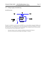
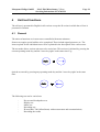
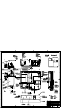
2.1
Block diagram, total unit
2.2
Mechanical structure
The major mechanical components of MAC 500 (MicroSmart) are the top and bottom shell. The
bottom shell is the basic element carrying the following sub-assemblies:
- Power supply module with system inlet, power supply unit and patient input.
- Battery
- Thermal array drive with paper magazine
- PCB MAC 500 (MicroSmart) with display
The top shell holds the keyboard which is linked to the PCB MAC 500 (MicroSmart) via a flexible
cable.
The 15-pin inlet plug for connecting the patient lead is located at the power supply module. It is
linked to the PCB MAC 500 (MicroSmart) via a flexible cable.
Marquette Hellige GmbH
3
MAC 500 (MicroSmart) V 2.xx
Servicing Instructions 227 470 35 D
Page 9
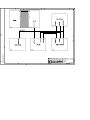
Description of the function
The description of the individual function blocks follows the Block diagram of the total unit in
chapter 1.1 and the function blocks of the P plans.
3.1
Power supply module
The power supply module comprises the following functions:
- System inlet with fuses
- Extended range power supply
- Patient input
These components are mounted on a carrier plate bolted into the bottom shell of the enclosure.
3.1.1 System inlet
The system inlet is defined as a system inlet module. It includes a three-pin IEC plug and two size 5
X 20 fuses accessible from the outside. The module is a component with snap-type function.
The system inlet is designed as "Universal Input", with the effect that no adjustment to the system
voltage ranges 100V~ ... 120V~ or 220V~ ... 240V~ is required.
3.1.2 Extended range power supply
The AC/DC power supply is designed as a universal extended range power supply. The power
supply unit is purchased complete and mounted on the carrier plate. The power supply supplies an
output voltage of 15.6V, from which all required voltages are generated.
- Input voltage range:
- Frequency range:
- Output:
- Efficiency
- Output voltage:
- Output current:
- Short-circuit-proof
- Approvals:
90VAC...264VAC
49Hz...65Hz
40W max.
≥ 70%
+15.6V ± 2%
2.6A max.
IEC601, UL544, CSA22.2-125, VDE750
Marquette Hellige GmbH
MAC 500 (MicroSmart) V 2.xx
Servicing Instructions 227 470 35 D
Page 10
The connection between the AC/DC power supply and the PCB MAC 500 (MicroSmart) is
implemented with a 2-pin lead as follows:
- on the AC/DC power supply:
-on the PCB MAC 500 (MicroSmart):
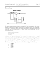
3.2
plugged
plugged
Battery
The battery is a rechargeable, maintenance-free lead battery. The battery is purchased complete and
mounted on the bottom shell of the enclosure.
- Rated voltage:
- Rated capacity:
12V
1.2Ah
The connection between the battery and the PCB MAC 500 (MicroSmart) is implemented with a 2pin lead as follows:
- on the battery:
- on the PCB MAC 500 (MicroSmart):
3.3
plugged
plugged
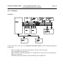
Printed circuit board (PCB) MAC 500 (MicroSmart)
The PCB MAC 500 (MicroSmart) holds the entire electronics of the unit. The electronics comprise
the following function groups:
-
Voltage supply and monitoring
On-Off electronics
Battery charge
Input voltage monitoring
Voltage supply +5V
-
Computer
Controller (Motorola 68332)
EPROM 512KByte
RAM 256KByte (MAC 500) or 512KByte (MAC 500 with measurement and
communication)
Configuration memory (EEPROM) 256Byte
Reset Generation
Alarm signal output
Real-time clock, buffered
Keyboard interface
IR interface (MAC 500 with measurement and communication (101 134 10) only)
Marquette Hellige GmbH
-
MAC 500 (MicroSmart) V 2.xx
Servicing Instructions 227 470 35 D
ECG recording and pre-processing (floating side)
- Protective input circuit
- Pre-amplifier
- AD converter
- PACE identification
- Electrode label
- Conductor label
- Filter and interface module
- Current supply
- Reference edit
-
Drive electronics and display
Array control
Temperature monitoring
Motor control
Voltage supply +24V
Photoelectric barrier analysis
Page 11
Marquette Hellige GmbH
MAC 500 (MicroSmart) V 2.xx
Servicing Instructions 227 470 35 D
Page 12
3.3.1 Voltage supply and monitoring
On-Off electronics
The unit is switched on and off via the ON/OFF key (on the membrane keypad). Enabling and
disabling operates via a toggle function: if the unit is switched off, press the ON/OFF key to switch
the unit on. If the unit is switched on, press the ON/OFF key to switch the unit off. The processor
can switch the unit off via the signal lead "G_OFF" if:
-
the input voltage is too low (exhaustive discharge protection for the battery)
the unit is not operated for any length of time (approx. 5 minutes)
Marquette Hellige GmbH
MAC 500 (MicroSmart) V 2.xx
Servicing Instructions 227 470 35 D
Page 13
Battery charge
The battery is charged by means of a special charging IC (UC3906) for lead batteries. The circuitry
monitors the charging current and the charge voltage. The charging IC has the same "temperature
coefficient" as a lead battery, with the effect that the battery charge is optimized over the specified
temperature range. The circuit operates as a "DUAL LEVEL FLOAT CHARGER", with three
distinct charging states:
- high current bulk charge state
- over-charge state
- float state
A charging cycle begins with "high current bulk charge state". In this state the battery is charged
with a constant current ( Imax ) while the battery voltage is monitored. The "over-charge state" sets
in as soon as a certain voltage value ( U12 ) is reached. In this state the battery voltage is kept at a
certain value ( UOC ), while the charging current is monitored. If the charging current drops to a
certain value ( IOC ), the "float state" sets in. At this point in time the battery capacity has risen to
almost 100%. In the "float state" the battery voltage is regulated to a precise value ( UF ).
The following values for voltage and current are selected when charging the 12V lead battery:
Imax
U12
UOC
IOC
UF
= 250mA
= 13.5V
= 14.2V
= 25mA
= 13.7V
Marquette Hellige GmbH
MAC 500 (MicroSmart) V 2.xx
Servicing Instructions 227 470 35 D
Page 14
Input voltage monitoring
The input voltage is monitored. If it drops to 11.3V, the LED_Bat lights up. This indicates that the
battery is in need of recharging. If the input voltage drops further to 10.3V, the signal "Batt_low"
will be activated. This signal is scanned by the processor. If it is active, the processor will
deactivate the unit (exhaustive discharge protection for the battery).
Marquette Hellige GmbH
MAC 500 (MicroSmart) V 2.xx
Servicing Instructions 227 470 35 D
Page 15
Voltage supply +5V
A 500KHz step-down switching regulator is used to generate the 5V voltage. The high-rate
switching frequency allows the entire circuit to be built up with SMD components. The switching
regulator is the module type LT1376. All the functions necessary for a step-down regulator are
integrated in this module.
Input voltage
Output voltage
Output current
Efficiency
Short-circuit-proof
10V...16V
+5 V ± 2%
min. 100 mA, max. 700 mA
> 80%
Marquette Hellige GmbH
MAC 500 (MicroSmart) V 2.xx
Servicing Instructions 227 470 35 D
Page 16
3.3.2 Computer
Controller
At the actual core of the unit is the Motorola Controller 68332 with the following integrated
components:
-
CPU32, computer core, internal 32 bit register, external 16 bit processing
TPU, independent timing processor
QSM with SCI for the implementation of a single RS 232 interface and a serial QSPI port
with up to 16 channels.
SIM with Chipselect generation, system monitoring, clock synthesizer
Marquette Hellige GmbH
MAC 500 (MicroSmart) V 2.xx
Servicing Instructions 227 470 35 D
Page 17
EPROM
ROM comprises one 4MBit EPROM module (= 512KByte). The data bus width is 16Bit.
Chipselect is the CSBOOT of the 68332.
RAM
RAM comprises a maximum of four static RAM modules with 128KByte each. The data bus width
is 16Bit. Each RAM chip receives its own chip-select signal (separate chip-select for High and Low
Byte) from the controller. This means that the RAM address is software-configurable. The basic
MAC 500 (MicroSmart) unit is only equipped with two RAMs, corresponding to a memory area of
256KByte. The memory capacity can be extended to 512KByte by adding two more RAMs. Access
time is 70 ns, this means that access is allowed without Wait States.
EEPROM
A serial EEPROM is used for the non-volatile memory. This is connected to the QSPI interface of
the 68332. The EEPROM has a memory area of 2048 Bit. (= 256Byte)
Reset Generation
Reset Generation is implemented with an integrated monitor module. It includes the voltage
monitoring with Reset Generation.
Acoustic signal output
The MAC 500 (MicroSmart) has a sound output for acoustic status/alarm signals. The pitch is
selected via a TPU channel of the 68332 (signal name: Beep). In addition, the volume can be varied
in 3 stages. Volume is set via the 3 signals LAUT1, LAUT2 and LAUT3.
Real-time clock
Provides the time and date. During operation it is supplied by the Supply logic; when the unit is
turned off, the unit switches over automatically to a 3V lithium cell which preserves the data. The
control signals for the clock (chipselect- read/write signal) are generated directly by the controller
(MC68332).
Marquette Hellige GmbH
MAC 500 (MicroSmart) V 2.xx
Servicing Instructions 227 470 35 D
Page 18
Keyboard interface
MAC 500 (MicroSmart)´s keyboard interface comprises a 5x5 matrix, although only a 4x4 matrix
is required and led to the keyboard. This allows 16 keys to be implemented. The keys are polled in
cycles. To do so, bit combinations are written into a buffer module (column) in cycles. An input
module (row) polled in cycles identifies if a key has been pressed (the combination of output
pattern and input pattern allows the pressed key to be determined).
The keyboard interface is located on the top byte of the data bus. The bits D8..D12 are used for the
keyboard (both input and output).
Both the output buffer and the input buffer are selected via a separate chipselect signal (chipselect
signal of the 68332).
The top two bits (D13...D15) of the input buffer are assigned with additional functions:
D13:
D14:
D15:
Hardware configuration bit (function undetermined) for future extensions
Default: 0
Battery monitor bit:
D14 = 1 ==> battery voltage < 11.3V
D14 = 0 ==> battery voltage > 11.3V
Battery monitor bit:
D15 = 1 ==> battery voltage < 10.3V
D15 = 0 ==> battery voltage > 10.3V
In addition to the 16 keys of the 4x4 matrix, the keyboard includes a key for switching the unit on
and off. Due to its special hardware configuration, this key is not integrated in the matrix.
Marquette Hellige GmbH
MAC 500 (MicroSmart) V 2.xx
Servicing Instructions 227 470 35 D
Page 19
The keyboard also includes 4 LEDs which are selected via the keyboard interface.
Line LED:
This LED is supplied directly from the 15V of the power supply. It shows
whether the unit is mains-operated (LED on) or supplied from battery (LED
off).
LED LOBAT: This LED is switched on and off by the controller. It shows that the battery is in
need of a recharge. A LOW level at the signal LED_LOBAT_ activates the
LED.
LED START: This LED indicates the status of the unit. It means that the unit is in an active state !
(processing, printing, etc. in progress). A LOW level at the signal
LED_START_ activates the LED.
LED STOP:
This LED indicates the status of the unit. It means that the unit is in a
passive state ! (processing, printing, etc. not in progress). A LOW level at
the signal LED_STOP_ activates the LED.
IR interface
The MAC 500 with measurement and communication is equipped with an IRDA interface.
The IRDA interface is selected via the RS232 interface of the 68332.
(Signals TXD and RXD of the '332).
In addition, an output port of the '332 determines if the IRDA module (TOI3232) is in the
configuration or in the communication mode.
Configuration signal: IR_BR_D = 0 ==> communication mode
IR_BR_D = 1 ==> configuration mode
Marquette Hellige GmbH
MAC 500 (MicroSmart) V 2.xx
Servicing Instructions 227 470 35 D
3.3.3 ECG recording and pre-processing
Page 20
Marquette Hellige GmbH
MAC 500 (MicroSmart) V 2.xx
Servicing Instructions 227 470 35 D
Page 21
The ASIC chipset HECTOR, consisting of 3 Ics, is used for ECG editing on the floating side. The
MAC 500 (MicroSmart) uses 2 ICs type SDM_HEC2 as AD converters and one IC type
DIGI_HEC2 as filter and interface module. Together with the protective input circuit, a floating
power supply and an interface insulated via optical coupler, the ECG editing is the floating section
of MAC 500 (MicroSmart) and is part of the PCB MAC 500 (MicroSmart). Discrete analog
components and a PIC processor are used for PACE detection.
ECG pre-processing comprises the following functional groups:
- Protective input circuit
- Pre-amplifier
- AD-converter
- PACE detection
- Electrode label
- Lead label
- Filter and interface module
- Power supply
- Reference editing
Protective input circuit
The protective input circuit is designed for the connection of 9 input electrodes and a push-pull
modulation, and includes 2 surge diverters and 18 high voltage diodes attached directly behind each
patient lead, as well as a hybrid (ECG input) which ensures the safety of the patient and of the
electronic components. Protection is only assured if a patient lead with series resistors of ≥ 8 kΩ is
used.
Overvoltages reaching the input are limited in the first stage to 90 V through surge diverters and
high voltage diodes. The voltage then passes via a 47 KΩ resistor from each input electrode on the
hybrid to 2 silicon diodes which limit the voltage to 1.2 V before it reaches the downstream
operations amplifier via 100 Ω. The overvoltages reaching the push-pull modulation output are also
limited to 1.2 V by two high voltage diodes over 3.3 KΩ and by two more diode line sections, while
the downstream operations amplifier is protected by 6.8 KΩ.
Patient safety is assured by the above two diodes on the hybrid 'ECG Input' and by the serial
resistance of 47 KΩ. In case of a defective input amplifier, the supply voltage of ± 5 V can reach the
input. The 100 Ω resistor on the hybrid limits the current flow to the diode, preventing damage to
the diode and limiting the supply voltage to 1.2 V. These 1.2 V are transmitted to the patient over
47 KΩ. The current flowing through it is limited to < 50 µA by the 47 KΩ.
Marquette Hellige GmbH
MAC 500 (MicroSmart) V 2.xx
Servicing Instructions 227 470 35 D
Page 22
Pre-amplifier
The 9 connectable electrode signals are transmitted to 9 low-noise operations amplifiers behind the
protective input circuit. These operations amplifiers amplify the input signals by the factor 3.8. This
pre-amplification is necessary in order to maintain the maximum noise value of 15 µVpp over the
entire system.
The R electrode is used as reference for the other electrodes, with the effect that the difference to
the R electrode always applies after each input amplifier. This means that the signal L-R is
available at the output of the operations amplifier for the L electrode. This configuration is
necessary in order to obtain a common-mode rejection in addition to the push-pull modulation. The
signal for the push-pull modulation is taken from the R electrode. The lead-offs are computed in
the software from these differential signals, with the R electrode being ignored through the renewed
differential formation in the appropriate lead-offs. The 8 differential signals which remain from the
original 9 electrode signals are transmitted to the Σ∆ modulators via a first order low pass with
1 kHz cut-off frequency.
AD converter
After the pre-amplifiers the signals are transmitted to analog-digital converters. The AD converters
are the Σ∆ modulator type. Two ICs of type SDM_HEC2 are used, each of which include 5
converters. The components for the internal integrators, used to adapt the modulators to their task,
are connected to the pins IM2x, OUT2x, REFx, OUT1x and IM1x. Each differential signal at the
output of the AD converter is resolved to 18 bit. With reference to the patient input, one LSB
corresponds to 5µV. Conversion is parallel in all channels, i.e. without any time offset. The
scanning frequency is 1kHz. Using the appropriate control words, it can also be set for 500 Hz and
2 kHz.
A square-wave signal is visible at the outputs OUT1 thru OUT5, which occurs synchronous with
the SWITCH signal. The duty factor of this square-wave signal depends on the input signal. This
data stream reaches the IC of type Typ DIGI_HEC2.
PACE detection
After the pre-amplifiers the 8 electrode signals lead to a multiplexer 1:8. Using the 3 outputs OP1,
OP3 and OP4 of the chip Chips DIGI_HEC2 the multiplexer selects the electrode to be used for
PACE detection. The selected signal is routed via a first order high pass with 23 Hz cut-off
frequency and amplified by the factor 1,000. The signal then reache a window comparator with a
4,5 mV threshold with reference to the input.
The 2 outputs of the window comparator are put to a PIC processor for further PACE analysis. This
processor supplies a PACE bit if the appropriate signals of the window comparators apply and if
the pulse duration is ≤ 2ms. The overshoot of the PACE pulse is suppressed by the PIC processor.
Marquette Hellige GmbH
MAC 500 (MicroSmart) V 2.xx
Servicing Instructions 227 470 35 D
Page 23
Electrode labeling
The 18 bit result of the analog-digital conversion shows if one or more differential signals are
overloaded, i.e. if the differential voltage with reference to the patient input is greater than 0.6V. A
hysteresis of 15 mV (0.6 - 0.615 V) is provided for the query. The query takes place simultaneously
for all 8 channels. The information (1 bit/channel) is transferred to the CPU via the serial port in the
word Electrode label.
The overload of a channel can be caused by excessive polarization voltage (>600 mV) or by a
detached electrode. In the latter case a voltage of 1 V is transmitted to the amplifier inputs via the
100 MΩ resistors on the protective input circuit.
One more circuit section is provided which handles the electrode error signal for the R and N
electrodes, because these cannot be detected individually with the converter overload. The
information is transmitted via INP1 and INP2 of the input port of ASIC DIGI_HEC2 in the status
word.
Lead labeling
Different leads can be connected to the patient input. The MAC 500 (MicroSmart) is designed for
use with a 5 and 10 wire patient lead. Lead labeling is identified by means of different voltage
values. For this purpose the 10 wire lead holds a 402 Ω resistor which, together with the series
resistor, generates a voltage in the range of 8.66 mV - 9.19 mV. A voltage in the range of 4.76 mV
- 5.05 mV with a resistance of 221 Ω is generated through the 5-wire lead. The voltage is measured
with the ninth Σ∆ modulator of the ASIC SDM_HEC2. This means that the chip set must be
configured for the transmission of 9 channels.
Current supply
A DC-DC converter is used which generates two alternating secondary voltages from the primary
5V with 125 kHz cycle. Two stabilized direct voltages of +5V and -5V are then generated from
both of these alternating voltages. The 125 kHz cycle is delivered by the CPU. To suppress radiated
noise, a reactor is provided in the current supply.
Reference voltage editing
The reference voltage has values between + 2.5 V and - 2.5 V. Special emphasis is placed on low
intrinsic noise because it directly affects the results of the Σ∆ modulator. The low pass immediately
following the reference element with a cut-off frequency of 8 Hz serves the same purpose. A
compromise had to be found between low noise and rapid stability of the reference voltage
immediately after enabling.
Marquette Hellige GmbH
MAC 500 (MicroSmart) V 2.xx
Servicing Instructions 227 470 35 D
Page 24
Filter and interface module
This IC (DIGI_HEC2) essentially incorporates the filter functions and the serial interface.
Fundamentally, the transfer bandwidth is 0 - 250 Hz for a scanning frequency of 1 kHz and 500 Hz,
with the upper cut-off frequency determined by a sinc filter of the 3rd order. The lower cut-off
frequency can be set within the range of 0.039 - 79.6 Hz (4.08 - 0.002s) by selecting the time
constant. Selecting this time constant also causes the separation of the DC content, which may be
superimposed over the ECG signal as polarization voltage. An IIR filter algorithm is used. The
algorithm only captures the lower 12 bits of the 18 bit result. This means that any sudden changes
at the input are always represented as changes with amplitudes < 20 mV. Limiting the display range
to ± 10 mV and selecting a suitable value query prevents sudden changes over the entire display
range when exceeding the range limits. A saturation value is delivered at about 10 mV, until the
measuring signal returns to within the display range.
For the useful signal transfer (ECG signal) the lower 12 bits are transferred with the selected
scanning frequency. However, there is also the option of using the appropriate control words for
special function tests to transfer the upper 12 bits without DC separation. In this case 1 LSB
corresponds to 320 µV. Possible function checks include testing the signal path, measuring the
polarization voltage, measuring the electrode impedance and testing the serial data transfer, all by
activating these functions by using the appropriate control words.
Measurements of the polarization voltage are allowed by transferring the upper 12 bits of the
converter result (1 LSB = 320 µV).
During the serial data test, a test word transmitted by the CPU will be returned immediately
thereafter by the ASIC DIGI_HEC2.
Marquette Hellige GmbH
MAC 500 (MicroSmart) V 2.xx
Servicing Instructions 227 470 35 D
3.3.4 Drive electronics and display
Page 25
Marquette Hellige GmbH
MAC 500 (MicroSmart) V 2.xx
Servicing Instructions 227 470 35 D
Page 26
Thermal array control
As the data output to the printhead is relatively time-consuming, special hardware has been
provided which relieves the processor of this task.
To drive the printhead, the CPU data for a printline are written block by block and at high speed
into a FIFO. A start signal generated by the CPU informs the printhead control TPH_CONTROL
(seated in a CPLD) that output to the thermal printhead can begin. Several "state machines" within
the TPH_CONTROL read 80 bytes from the FIFO and transmit the serialized data to the printhead.
At the end of the transfer the CPLD generates the latch signal for the array and the trigger signal for
the heat duration generation.
The speed-related heat duration is software-selected. The heat duration value is gained via the
pulse-pause ratio of a TPU channel functioning as PWM channel. After the PWM signal has been
routed via a low pass, a DC voltage proportional to the PWM ratio which is used for setting the
heat duration. With each trigger pulse for the heat duration generation, a capacitor charged via a
constant current source is discharged and a heat duration cycle is started. The linear voltage
increase at the capacitor is compared in a comparator with the analog value supplied by the PWM
channel. If the analog value is exceeded, the heat duration pulse is terminated. In addition, the heat
duration is adjusted as a factor of the printhead substrate temperature. The temperature-dependent
voltage obtained via the array thermistor is added to the PWM voltage supplied by the TPU
channel in a summing amplifier.
The supply voltage of the thermal array can be switched off via the power switch if:
- array voltage < 19.2V
- reset active
- motor not running
- array overheated
Temperature monitoring
An array excess temperature monitoring device is fitted to protect the thermal array. Using a
comparator, the voltage of the thermistor is compared with a reference value. If the array
temperature of 60°C is exceeded, the comparator signals this to the processor.
Marquette Hellige GmbH
MAC 500 (MicroSmart) V 2.xx
Servicing Instructions 227 470 35 D
Page 27
Motor control
The stepping motor is controlled in three stages. A TPU channel is used in the controller 68332
which generates the frequency of the stepping sequence. Using this frequency, the "state machine"
FSM_STEPPER generates the sequence for the quater step operation of the stepping motor in the
complex PLD. From the control sequence the motor driver module generates the signals for both
motor windings in two full bridges. To reduce power loss, the windings are controlled with
constant current.
The motor speed is set via the frequency of the stepping sequence. To avoid stepping loss, the
software changes the frequency of the stepping sequence when the motor is started.
The "state machine" has one input allowing the direction of rotation to be changed.
Once the motor is started, the processor does not require any more processing power for the motor.
No compensation is required for the motor. The internal TPU stepping motor control is not used
because it is designed for a positioning system and would constantly require CPU power for
continuous operation. To save energy during printing breaks, the motor driver is released or locked
via the lead MOTOR_INH_.
Photoelectric barrier analysis
The reflective light barrier has several functions:
-
checks if paper is available
mark reader in case of Z-fold paper
identifying an open paper
monitors if motor runs when using Z-fold paper
The paper signal PAPER_ERR_ reaches the CPLD via a comparator. The error state is stored in the
CPLD (signal PAPER_).
PAPER_ERR_ = PAPER_ = low
no paper, flap open, or mark below sensor
The processor polls the lead PAPER_ and resets the signal PAPER_ back to high via the lead
PAPER_RES.
Marquette Hellige GmbH
MAC 500 (MicroSmart) V 2.xx
Servicing Instructions 227 470 35 D
Page 28
Voltage supply +24V
Besides the logic supply, the thermal array needs a 24V power supply to current-activate the dots.
This 24V voltage is also used for the stepping motor. The voltage is generated by the switching
regulator MC33063. The switching regulator works in step-up operation in connection with the
external power MOSFET. For brief peak loads, the electrolytic storage capacitor supplies the
necessary power.
Input voltage
Output voltage
Output current
Efficiency
10V...16V
+23.5 V ± 5%
min. 0 mA, max. 600 mA
≥ 80%
Marquette Hellige GmbH
3.4
MAC 500 (MicroSmart) V 2.xx
Servicing Instructions 227 470 35 D
Page 29
Internal interfaces
This chapter deals with the pinning, the function and meaning of the signals of the internal
interfaces of the function components. These interfaces include:
-
Interface, power supply
Interface, display
Interface, thermal array
Interface, motor
Interface, photoelectric barrier
Interface, keyboard
Interface, ECG port
3.4.1 Interface, power supply
Plug designation:
PSCON/
Plug connector 4-pin, horizontal (90 °), reverse voltage protection implemented mechanically.
The function of the individual pins is shown in the following table. The definition in terms of
input/output is as seen from the PCB MAC 500 (MicroSmart).
Signal name
I/O
Meaning
Level
Polarity
Pin No.
PSCON1
I
batt +
12V
---
1
PSCON2
I
batt -
GND
---
2
PSCON3
I
power supply
+
+15.6V
---
3
PSCON4
I
power supply
-
GND
---
4
Marquette Hellige GmbH
MAC 500 (MicroSmart) V 2.xx
Servicing Instructions 227 470 35 D
Page 30
3.4.2 Interface, display
Plug designation:
AE/
Socket connector 1 x 14-pin, upright (180 °), reverse voltage protection implemented
mechanically.
The function of the individual pins is shown in the following table. The definition in terms of
input/output is as seen from the PCB MAC 500 (MicroSmart).
Signal name
I/O
Meaning
Level
Polarity
Pin No.
Vss
---
Ground
0V
---
1
VDD
---
Supply
+5V
---
2
V0
---
Contrast voltage
0-5V
---
3
RS
O
Register select
TTL
R/W
O
Read/Write
TTL
---
5
E
O
Enable
TTL
active-high
6
DB8
I/O
Data
TTL
---
7
DB9
I/O
Data
TTL
---
8
DB10
I/O
Data
TTL
---
9
DB11
I/O
Data
TTL
---
10
DB12
I/O
Data
TTL
---
11
DB13
I/O
Data
TTL
---
12
DB14
I/O
Data
TTL
---
13
DB15
I/O
Data
TTL
---
14
4
Marquette Hellige GmbH
MAC 500 (MicroSmart) V 2.xx
Servicing Instructions 227 470 35 D
Page 31
3.4.3 Interface, thermal array
Plug designation:
AA/
Socket connector 2 x 15-pin upright (180 °), Caution! No reverse voltage protection!
The function of the individual pins is shown in the following table. The definition in terms of
input/output is as seen from the PCB MAC 500 (MicroSmart).
Signal name
I/O
Meaning
Level
Polarity
Pin No.
VH
---
+24V
+24V
---
1
VH
---
+24V
+24V
---
2
GND
---
+24V
0V
---
3
VH
---
Ground
+24V
---
4
GND
---
Ground
0V
---
5
GND
---
Ground
0V
DATA IN 1
I
Data input 1
TTL
---
7
DATA OUT 1
O
Data input 1
TTL
---
8
DATA IN 1
I
Data input 2
TTL
---
9
DATA OUT 2
O
Data output 2
TTL
---
10
STROBE 1
I
Strobe 1
TTL
active high
11
STROBE 2
I
Strobe 2
TTL
active high
12
THERMISTOR 1
---
NTC resistor
---
---
13
LATCH
I
Array latch
TTL
active high
14
Logic Supply
+5V
---
15
VDD
6
NC
---
---
---
---
16
THERMISTOR 2
---
NTC resistor
---
---
17
CLOCK
I
Array clock
TTL
L->H
18
STROBE 3
I
Strobe 3
TTL
active high
19
STROBE 4
I
Strobe 4
TTL
active high
20
DATA IN 3
I
Data input 3
TTL
---
21
Marquette Hellige GmbH
MAC 500 (MicroSmart) V 2.xx
Servicing Instructions 227 470 35 D
Page 32
DATA OUT 3
O
Data output 3
TTL
---
22
DATA IN 4
I
Data input 4
TTL
---
23
DATA OUT 4
O
Data output 4
TTL
---
24
GND
---
Ground
0V
---
25
GND
---
Ground
0V
---
26
GND
---
Ground
0V
---
27
VH
---
+24V
+24V
---
28
VH
---
+ 24V
+24V
---
29
VH
---
+ 24V
+24V
---
30
Marquette Hellige GmbH
MAC 500 (MicroSmart) V 2.xx
Servicing Instructions 227 470 35 D
Page 33
3.4.4 Interface, motor
Plug designation:
AC/
Plug connector 6-pin, upright (180 °), reverse voltage protection implemented mechanically.
The function of the individual pins is shown in the following table. The definition in terms of
input/output is as seen from the PCB MAC 500 (MicroSmart).
Signal name
I/O
Meaning
Level
Polarity
Pin No.
Q11
O
Field coil 1
+24V
---
1
Q12
O
Field coil 1
+24V
---
2
Q21
O
Field coil 2
+24V
---
3
Q22
O
Field coil 2
+24V
---
4
3.4.5 Interface, photoelectric barrier
Pin designation:
AB/
Zero power flat membrane connector 4-pin, upright (180 °), reverse voltage protection
implemented mechanically.
The function of the individual pins is shown in the following table. The definition in terms of
input/output is as seen from the PCB MAC 500 (MicroSmart).
Signal name
I/O
Bedeutung
Level
Polarity
Pin No.
SENSOR_TR
I
Collector Phototrans.
0-5V
---
1
SENSOR_GND
---
Ground
0V
---
2
SENSOR_LED
O
Anode LED
2.5V
---
3
---
---
Free
---
---
4
Marquette Hellige GmbH
MAC 500 (MicroSmart) V 2.xx
Servicing Instructions 227 470 35 D
Page 34
3.4.6 Interface, keyboard
Plug designation:
AS/
Zero force flat membrane connector 18-pin, upright (180 °), reverse voltage protection
implemented mechanically.
The function of the individual pins is shown in the following table. The definition in terms of
input/output is as seen from the PCB MAC 500 (MicroSmart).
Signal name
I/O
Meaning
Level
Polarity
Pin No.
LED_LOBAT
O
Anode battery LED
+5V
---
1
LED_NETZ
O
Anode system LED
+15V
---
2
GND
O
Ground
GND
---
3
COLUMN4
O
Matrix column 4
+5V
---
4
COLUMN3
O
Matrix column 3
+5V
---
5
ROW4
I
Matrix row 4
+5V
---
6
COLUMN2
O
Matrix column 2
+5V
---
7
COLUMN1
O
Matrix column 1
+5V
---
8
COLUMN5
O
Matrix column 5
+5V
---
9
ROW5
I
Matrix row 5
+5V
---
10
ROW3
I
Matrix row 3
+5V
---
11
ROW2
I
Matrix row 2
+5V
---
12
ROW1
I
Matrix row 1
+5V
---
13
ON_OFF
O
Key ON/OFF
+15V
---
14
GND
O
Ground
GND
---
15
LED_STOP
O
Anode STOP LED
+5V
---
16
LED_START
O
Anode START LED
+5V
---
17
GND
O
Ground
GND
---
18
Marquette Hellige GmbH
MAC 500 (MicroSmart) V 2.xx
Servicing Instructions 227 470 35 D
Page 35
3.4.7 Interface, ECG input
Plug designation:
AH/
Socket connector 16-pin, horizontal (90 °), reverse voltage protection implemented
mechanically.
The function of the individual pins is shown in the following table. The definition in terms of
input/output is as seen from the PCB MAC 500 (MicroSmart).
Signal name
I/O
Meaning
Level
Polarity
Pin No.
C2
I
Input C2
---
---
1
R
I
Input R
---
---
2
C3
I
Input C3
---
---
3
L
I
Input L
---
---
4
C4
I
Input C4
---
---
5
F
I
Input F
---
---
6
C5
I
Input C5
---
---
7
C1
I
Input C1
---
---
8
C6
I
Input C6
---
---
9
---
---
---
---
10
AGND
O
Screen
---
---
11
N
O
N-pp modulator
---
---
12
---
---
---
---
13
---
---
14
---
---
15
---
---
16
--PL
I
---
---
Lead label
Marquette Hellige GmbH
3.5
MAC 500 (MicroSmart) V 2.xx
Servicing Instructions 227 470 35 D
Page 36
External interfaces
MAC 500 (MicroSmart) has only three interfaces to the outside:
- Line inlet
- Patient input
3.5.1 Line inlet
The interface of the line inlet has been implemented in the unit by a 3-pin, standardized
connector for non-heating appliances. Line connection via a 3-pin line cable with protective
conductor.
Plug designation:
D/
3.5.2 Patient input
Patient input and plug of the patient lead have been redesigned because the MAC 500
(MicroSmart) guarantees the required defibrillation protection only in connection with the
patient lead. This means that all previously used patient leads can no longer be used. This also
applies to the suction system with integrated pump.
Plug designation:
AF/
Sub-D socket casing, 15-pin
The function of the individual pins is shown in the following table. The definition in terms of
input/output is as seen from the PCB MAC 500 (MicroSmart) (patient input).
PinNo.
I/O
Designation
Function
1
Input
C2
Input electrode C2
2
Input
C3
Input electrode C3
3
Input
C4
Input electrode C4
4
Input
C5
Input electrode C5
5
Input
C6
Input electrode C6
6
Output
S
Screen
7
---
NC
---
8
Input
PL
Label of patient lead used
Marquette Hellige GmbH
MAC 500 (MicroSmart) V 2.xx
Servicing Instructions 227 470 35 D
9
Input
R
Input electrode R
10
Input
L
Input electrode L
11
Input
F
Input electrode F
12
Input
C1
Input electrode C1
13
---
NC
---
14
Output
N
Output electrode N (pp-modulator)
15
---
NC
---
Page 37
3.5.3 IR interface
The MAC 500 with measurement and communication is equipped with an IrDA interface. This
interface has the following properties:
*
*
*
*
*
*
*
Transmission rate: 9600 Baud
Data bits: 8
Stop bits: 1
Parity: no
no hardware handshake
half duplex
Range max. 3 meters (direct visual connection to receiver)
3.6
Delimitations
The following operating modes have not been implemented in MAC 500 (MicroSmart):
- No Ergometrics
- No spirometry
- No Late Potentials, no RR variability
- No phono, no US doppler
A scope output is not available.
No analog inputs.
No ECG trigger output.
Use of NC batteries not allowed.
Use of primary batteries not allowed.
Marquette Hellige GmbH
MAC 500 (MicroSmart) V 2.xx
Servicing Instructions 227 470 35 D
Page 38
Marquette Hellige GmbH
4
MAC 500 (MicroSmart) V 2.xx
Servicing Instructions 227 470 35 D
Page 39
Unit test functions
The self-test is presented in English in all versions except the D version in which the self test is
presented in German.
4.1
General
The unit test functions are in most cases controlled with menu-assistance.
Some tests require special utilities to be completed. These include signal generator, etc. The
items required for the individual tests will be explained in the description of the various tests.
The test mode allows various unit tests to be carried out. This unit test is initiated by pressing the
current operating mode key and the "arrow key right" at the same time. E.g.:
Quit the test mode by pressing any operating mode key and the "arrow key right" at the same
time.
The following test can be carried out:
-
Key test and loudspeaker test
Display test
Motor test
Recording test
IR test (MAC 500 (MicroSmart) with measurement and communication)
Recording the results
Marquette Hellige GmbH
4.2
MAC 500 (MicroSmart) V 2.xx
Servicing Instructions 227 470 35 D
Page 40
Key test and loudspeaker test
By pressing a key, its appropriate function is shown on the display. Example:
Key
Display
Auto
5 (speed)
10 (sensitivity)
→
etc.
KEY_AUTO
5 mm/s
10 mm/mV
CUR_RIGHT
The Start/Stop key is tested automatically by activating/deactivating the test. An alarm signal is
triggered when pressing the "loudspeaker key". By continuously pressing the key the volume
changes in the following rhythm:
-
soft-medium-loud-soft-medium ... etc.
4.3
Display test
After activation, the active test will be displayed. Using the arrow control keys (←,→) all pixels
of the display can now be switched on and off in alternation. Pressing the Start/Stop key will end
the test and display the next one.
4.4
Motor test
After activating the motor test, the current state (STOP) and the preselected speed will be
displayed. In this state the motor test can either be started or the preselected speed can be
changed. Once the test has been started, a mark will be printed on the paper every second during
operation. The spacing between these marks allows conclusions to be drawn on speed and its
accuracy. The speed can also be modified without "Stop". Position of the mark: top and bottom
of the sheet.
Height of mark: 5mm
Width of mark: 1 dot
Quit the test by pressing any arrow key (←,→). The next test will be displayed.
Marquette Hellige GmbH
4.5
MAC 500 (MicroSmart) V 2.xx
Servicing Instructions 227 470 35 D
Page 41
Recording test
After activating the recording test, the preselected speed and the sensitivity will be displayed. In
this state (STOP) the parameters can be modified using the appropriate keys. After the start the
first two channels will be recorded with the selected parameters. Other channels cannot be
selected. Recording is continuous and must be aborted by pressing the Start/Stop key. Quit the
test by pressing any arrow key (←,→). The next test will be displayed.
4.6
IR test (MAC 500 with measurement and communication only)
After activating, test the IR interface as follows:
Arrow key ->:
Arrow key <-:
a test string is continuously transferred until the Start/Stop key is activated
data can be received from a remote station and be shown on the display.
Initiate data acceptance with the arrow key " <- ". The interface is set for
the receiving mode when striking this key. From this point on the operator
has 20 seconds for an entry (data transfer). Always conclude a transfer by
striking the carriage return key. Note that there is a minimum and
maximum number of transferable characters. At least two valid characters
plus carriage return must be transferred to make them show on the display.
If more than 200 characters are transferred before carriage return, a buffer
overflow will be signaled. If there is no overflow, the first 16 of the
transferred characters will appear on the display. If, after activating data
acceptance, no characters have been received within 20 seconds, an
appropriate error message will be shown.
Quit the test by pressing the Start/Stop key again.
4.7
Recording the results
After activating, the test results will be written out. This output supplies data on the software
contained in the unit (reference number, version number, date of preparation of the firmware),
the results of the tests carried out during power-up, and details on the connected patient lead.
The sector listed under RAM has the following meaning:
MAC 500 (MicroSmart)
0
256KByte
040000h
RAM sector on the PCB MAC 500 (MicroSmart)
Marquette Hellige GmbH
MAC 500 (MicroSmart) V 2.xx
Servicing Instructions 227 470 35 D
Page 42
MAC 500 with measurement and communication
0
512KByte
080000h
RAM sector on the PCB MAC 500 (MicroSmart)
The sector listed under EPROM has the following meaning:
MAC 500 (MicroSmart) and MAC 500 with measurement and communication
800000
512KByte
880000h
ROM sector on the PCB MAC 500 (MicroSmart)
The test results explained under 3.1.6 are determined during the self-test which is always
performed after power-up. If any errors are detected, a display message appears after the test,
indicating the possible error. The following error codes are used to localize the error:
4.7.1 Error codes
The following error codes are shown on the display in connection with the message "Test
failed!":
CODE:
0
1
2
3
4
5
6
IRAM
VECTOR
RAM1 RAM
RAM2 RAM
EPROM
ASIC
E2PR
error in the internal RAM of the 68332
error in the vector table
error in the sector 0-256KByte
error in the sector 256-512KByte
Checksum error in the EPROM
error interface to ASIC
error EEPROM
Marquette Hellige GmbH
4.8
MAC 500 (MicroSmart) V 2.xx
Servicing Instructions 227 470 35 D
Page 43
Additional functions for final test
A number of additional functions can be selected in the test mode by striking certain key
combinations. These functions are primarily intended for final testing. This is why they are not
explicitly available as selectable items within the test mode. Instead, they can be reached via
certain key combinations. These are:
-
setting time and date
reading in the serial number
Setting time and date
This mode can be reached from the selection level for appliance tests with the key combination
"Man + Config".
Use the "-->" key to select the setting for the date, and the key "<--" to select the setting for the
time. The setting steps which follow are designed for an automated setting. Instead of showing
the current data, the unit will display the setting returned to "zero".
Reading in the serial number for determining the option key
(MAC 500 with measurement and communication only)
Necessary equipment for reading in the serial number:
Hardware
PC or Laptop
Interface Cable PC - Irda Adapter (Partnumber 223 426 01)
Irda Adapter (Partnumber 930 117 72)
Software
use Terminal-Program (Windows 3.11) or
Hyperterminal-Program (Windows 95and Windows NT)
Transfer parameters: 9,600 baud rate, 1 stop bit, no parity, 8 data bits
Preparation
MAC 500 with measurement and communication
The serial number is read in via the Irda interface. Starting from the selection level for the
appliance test, the read-in function for the serial number is reached via the key combination
"Arrhy + Config". Only numerical characters (maximum 9) will be accepted.
PC or Laptop
Connect the Interface Cable to a free COM port. Connect the Irda Adapter to the Cable. Start the
Terminal-Program for Windows 3.11 and Hyperterminal-Program for Windows 95/98/NT..
Select the transfer parameter and the COM port.
Marquette Hellige GmbH
MAC 500 (MicroSmart) V 2.xx
Servicing Instructions 227 470 35 D
Page 44
Transferring the serial number
1. MAC 500 (MicroSmart):
Press the keys Arrhy and Config simultaneous. The unit immediately moves into the receiving
mode.
On the display appears
Trans. Ser No !
Receive Data ...
Important: Within 20sec, you have to type in the serial number
2. PC:
Type in the serial number and press CR-key
3. MAC 500 (MicroSmart):
If no serial number is transferred or the receiving-time is passed before the serial number is
transferred, an ERROR-message ("Receive Error" ) appears on the display.
After a short time the message "Ser No false" appears on the display. You have to start again
from step 1.
If the transfer was successful, the transferred serial number appears on the display. After a short
time, the unit comes back to the unit test mode. Switch Off the unit. Switch On the unit and
activate again the unit test mode. Activate "Results". The transferred serial number must appear
on the printout.
A second possibility to enter the serial number into the MAC 500 (MicroSmart) is via keypad.
Note: This performance is only possible from version 2.2 and higher.
The following procedure is required to enter the serial number into the MAC 500 (MicroSmart):
-
Switch off the unit
Switch on the unit while holding the key combination BEEP +10 mm/mV
On the display appears the following text <Enter Ser. No.>
Enter the serial number with the keys ← →
Confirm every digit with the start/stop key
After enter the last digit, the following text appears <Ser. No stored>
Switch off and on the device to activate the new serial number
If no serial number is entered, the unit will show an appropriate 5 second visual and acoustic
signal each time the unit is switched on.
Marquette Hellige GmbH
4.9
MAC 500 (MicroSmart) V 2.xx
Servicing Instructions 227 470 35 D
Page 45
Re-locking option
The open option can only be re-locked by deleting the entered option key. To re-lock the open
option, proceed as follows:
-
switch off the unit
press the key combination "BEEP + 20/35" and switch on the unit at the same time
the unit signals "option cleared"
Explanation:
BEEP:
20/35:
loudspeaker key
filter key 20/35 Hz
Marquette Hellige GmbH
MAC 500 (MicroSmart) V 2.xx
Servicing Instructions 227 470 35 D
Page 46
Marquette Hellige GmbH
MAC 500 (MicroSmart) V 2.xx
Servicing Instructions 227 470 35 D
5
Selecting the type of appliance
5.1
General
Page 47
The unit provides functions for selecting the type of appliance. The type of appliance defines
certain performance features of the unit. The following types of appliances are available:
Type: International
After power-up the unit displays "MAC 500 (MicroSmart)". The
company name "GE marquette" is printed on the recordings. The
electrodes are labeled "R, L, F, N, C1, C2, C3, C4, C5, C6". The
date format is "dd.mm.yy". The following languages can be
selected in the configuration:
German, English, French, Netherlands, Italian, Spanish,
Portuguese, Danish, Norwegian, Swedish, Finnish, Russian,
Polish, Czech, Hungarian, Bulgarian, Macedonian. The line filter
is set for 50 Hz.
Type: USA
Keyboard with text instead of icons. Company name
"GE marquette" appearing on the unit and on the type plate. The
company name "GE marquette" is printed on the recordings. A
place holder for Name instead of the name of the unit is printed on
the real-time recordings (Man/Arrhy). Default (works) setting the
notation (electrode labels) is AAMI. The date format is
"mm.dd.yy". Languages: English, français, español, português. No
data communication, i.e. the following items are not displayed in
the configuration: copy function, data transfer, tel. No. Default
(works) setting for override function is On. The line filter is set for
60 Hz. Default (works) setting for paper format is Roll (cannot be
altered). The time format is "am" and "pm". Default (works)
setting for the recording format is: sequential, rhythm record Yes.
Lead group definitions:
Stnd (standard) in place of Eint (Einthoven)
Aug (augmented) in place of Gold (Goldberger)
V1-3 (chest V1-3) in place of Wil1 (Wilson 1)
V4-6 (chest V4-6) in place of Wil2 (Wilson 2)
Program designation on recording and on display:
12Ld in place of Auto
3Ld in place of Man
HR^ in place of Arrh
Type: USA2
Device name MAC 500 in place of MicroSmart. Otherwise as
type "USA"
Marquette Hellige GmbH
MAC 500 (MicroSmart) V 2.xx
Servicing Instructions 227 470 35 D
Type: Asia
Company name "GE marquette" appearing on the unit and on the
type plate. The company name "GE marquette" is printed on the
recordings. The following languages can be selected in the
configuration: German, English, French. Default (works) setting
the notation (electrode labels) is AAMI. Otherwise as type
"International"
5.2
Page 48
Selecting the type of appliance
The following procedure is required to select the type of appliance:
-
switch off the unit
switch on the unit while holding the key combination for "delete Configuration" down (see
table below)
the unit signals Config cleared
switch off the unit
switch on the unit while holding the key combination for the type of appliance down.
Key codes for selecting the type of appliance
Key combination
Appliance type
Key loudspeaker + 5 mm/mV
delete Configuration (EEPROM )
Key loudspeaker + 50 mm/mV
International
Key loudspeaker + 25 mm/mV
USA
Key loudspeaker + 5 mm/mV
USA2
Key loudspeaker + 20 mm/mV
ASIA
Key loudspeaker + 10 mm/mV
Enter Serial number ***
Key loudspeaker + 20/35
Delete Option Codes
***only important for MAC 500 with measurement and communication (MicroSmart MC)
The possibility to enter the serial number via keypad is only available from version 2.2 and
higher.
In version 2.1 and version 2.0 the serial number can entered only by Irda Interface, refer to
service manual section 4.8 (Reading in the serial number).
Marquette Hellige GmbH
MAC 500 (MicroSmart) V 2.xx
Servicing Instructions 227 470 35 D
Explanatory notes:
BEEP:
5mm/mV:
20mm/mV:
10 mm/V:
50mm/s:
25mm/s:
5mm/s:
20/35 mm/s:
loudspeaker key
sensitivity key 5mm/mV
sensitivity key 20mm/mV
sensitivity key 10 mm/mV
speed key 50mm/s
speed key 25mm/s
speed key 5mm/s
Filter key (20/35 Hz)
Page 49
Marquette Hellige GmbH
MAC 500 (MicroSmart) V 2.xx
Servicing Instructions 227 470 35 D
Page 50
Marquette Hellige GmbH
6
Repair notes
6.1
Safety notes
MAC 500 (MicroSmart) V 2.xx
Servicing Instructions 227 470 35 D
Page 51
When replacing electronic components, always implement ESD protection.
Return replacement PCBs only in ESD packagings.
Return defective or exhausted batteries to the factory for proper disposal.
6.2
Component replacement
For the following items, observe the safety notices in chapter 4.1.
Caution:
To avoid damage to the thermal array, always fully discharge with a resistor
approx. 68 Ω the condenser C1 (located on the PCB) before replacing/exchanging
the PCB or the thermal array.
Opening the unit
To open the MAC 500 (MicroSmart), remove the 4 attachment screws on the base of the unit,
open the paper flap, carefully lift off the upper shell of the enclosure, disconnect the keyboard.
When reassembling the unit, make sure that none of the cables are pinched.
Replacing the Lithium battery
By replacing the Lithium-Battery heed on the polarity.
Caution:
Use only original Marquette Hellige batteries (see chapter 8, Spare Parts List)
Return empty batteries to the factory for proper disposal.
Marquette Hellige GmbH
MAC 500 (MicroSmart) V 2.xx
Servicing Instructions 227 470 35 D
Page 52
Replacing the battery
Open (do not cut) the two reusable cable ribbons by pressing on the attachment latch. Detach the
plug connection G and replace the battery.
Caution:
Use only original Marquette Hellige batteries (see chapter 8, Spare Parts List)
Return defective batteries to the factory for proper disposal.
Place the battery in the compartment, tighten the cable ribbons and reconnect the plug
connection G
Replacing the recorder unit:
Open the recorder lid and take out the two screws on the base of the recorder enclosure. Detach
the plug for motor, array control and flat ribbon cable for the mark reader from the PCB MAC
500 (MicroSmart). Disconnect the protective circuit connection on the power supply.
The complete recorder enclosure can now be removed.
Replacing the thermal array:
The thermal array can only be removed from the bottom of the recorder enclosure.
Carefully push the side wall of the recorder enclosure to the outside. At the same time push the
array holder forward until it detaches from its locking mechanism. Then remove the thermal
array from the top. The two springs will come undone. When re-installing the thermal array, use
pincers to lock the springs back in position.
Replacing the PCB MAC 500 (MicroSmart)
Before replacing the PCB, print out the configuration selected by the user, if possible.
With the unit open, first disconnect the plug connection PSCON to the power supply, then
disconnect the remaining plugs to the drive (plug connection AB, AA, AC) and to the ECG input
(plug connection AH). Then remove the two attachment screws.
Check if the solder bridge of the lithium battery of the real-time clock (BA 500) is properly
soldered. Install the new PCB and reconnect the plugs.
Setting the clock is described in the operating instructions.
Accept the configuration selected by the user (if known). If not, use the works settings.
Set the contrast with the display used.
Marquette Hellige GmbH
MAC 500 (MicroSmart) V 2.xx
Servicing Instructions 227 470 35 D
Page 53
Important Service Note
Valid for Pcb. With Part No.: 303 445 45
303 445 44
389 004 24
389 004 23
After the installation of the exchange Pcb. MicroSmart and after having switched on the Device,
the message <Device unknown> might appear on the display.
The Reason: The required Device Version
(International / USA / USA2 / ASIA)
is not stored up on the EEPROM.
If the Device is working in the user mode, the required Device must be entered.
Please follow the instruction in section 5.2.
Replacing the display
With the unit open, first detach the two attachment screws of the display. Pull the display off the
plug connection AE. Plug in the new display and re-attach.
Set the contrast with new display
Replacing the power supply
First remove the PCB MAC 500 (MicroSmart) (see above). Detach the four attachment screws
on the metal carrier base (power supply module). Take out the power supply module. The power
supply is bolted to the metal carrier base with 3 attachment screws. Disconnect the plug
connections CB and CA. Detach the three attachment screws. Replace the power supply.
Replacing the patient input
First remove the PCB MAC 500 (MicroSmart) (see above). Detach the four attachment screws
on the metal carrier base (power supply module). Take out the power supply module. The patient
input is bolted to the metal carrier base with 2 attachment screws. Detach the attachment screws.
Marquette Hellige GmbH
MAC 500 (MicroSmart) V 2.xx
Servicing Instructions 227 470 35 D
Page 54
Marquette Hellige GmbH
7
MAC 500 (MicroSmart) V 2.xx
Servicing Instructions 227 470 35 D
Page 55
Troubleshooting
Mains plug connected; the unit cannot be switched on
-
green LED of power indicator light fails to light up and unit cannot be switched
on:
line power lead defective or not connected properly?
primary fuses in line inlet module defective?
plug CB on power supply properly connected?
plug CA on power supply properly connected?
plug PSCON on PCB MAC 500 (MicroSmart) properly connected?
keyboard properly connected via plug AS on PCB MAC 500 (MicroSmart)?
if all items above are OK: ===> power supply unit defective
green LED of power indicator light lit, unit still cannot be switched on:
On/off key of unit defective?
fuses SI500 on PCB MAC 500 (MicroSmart) defective?
if all items above are OK: ===> PCB MAC 500 (MicroSmart) defective
Battery operation selected; unit cannot be switched on
-
-
plug connection G on battery properly connected?
battery exhausted/discharged?
connect mains plug, green LED of power indicator lights must light up and unit
can be activated. If not, see above under "Mains plug connected; unit cannot be
switched on".
battery charge activated when connecting the mains plug
after 10 minutes charging, disconnect the mains plug, can the unit be switched on
and a recording be triggered?
===> battery defective or capacity too low
===> or battery charge on PCB MAC 500 (MicroSmart) defective
Blank display
-
after power-up, does the yellow Stop LED on the keyboard light up?
if not: - see under "Unit cannot be ..... switched on".
Contrast bad? (change contrast)
Alarm signal approx. 5 sec. after power-up of the MAC 500 (MicroSmart)?
(indicates that the self-test is complete).
if yes; - display properly connected?
if yes: ===> display defective?
===> or control on the PCB MAC 500 (MicroSmart) defective.
Marquette Hellige GmbH
MAC 500 (MicroSmart) V 2.xx
Servicing Instructions 227 470 35 D
Page 56
Error detected during self-test
If an error is detected during the self-test, the display shows the message "Test failed !" in
addition to the error code and a brief description. The error codes are described in chapter 3.7.1.
MAC 500 (MicroSmart) fails to print, no paper feed
Carry out the following test in the "Man" mode.
-
paper available? paper correctly inserted? paper feed disruption?
paper flap properly latched in both locking mechanisms?
green Start LED must light up after pressing the Start/Stop key
if not: ===> PCB MAC 500 (MicroSmart) defective
motor supply lead defective? plug AC properly connected?
motor blocked? (check drum, transmission)
measure the voltage +24V on diode D506 (cathode). 24V available?
- if yes:
===> motor defective?
===> or PCB MAC 500 (MicroSmart) defective (motor control)
Paper feed works, nothing printing out
-
paper flap properly latched in both locking mechanisms?
plug connection AA properly connected?
measure the voltage +24V on diode D506 (cathode). 24V available?
a great deal printed recently, array still over-heated? allow to cool off
none of the above malfunctions applies:
===> PCB Control defective?
===> or thermal array defective
MAC 500 (MicroSmart) only prints in top or bottom part of record
-
paper flap engaged only on one side
MAC 500 (MicroSmart) prints, only zero lines are written
-
electrodes correctly attached?
patient lead defective? (e.g. N-lead defective)
contact problems on patient input of MAC 500 (MicroSmart)?
none of the above malfunctions applies:
===> PCB MAC 500 (MicroSmart)
defective
Marquette Hellige GmbH
MAC 500 (MicroSmart) V 2.xx
Servicing Instructions 227 470 35 D
8
Maintenance and care
8.1
Technical inspection
Page 57
Technical inspections must be carried out once every year.
Note!
The following checks and tests must be carried out by personnel who are qualified to maintain
this equipment.
Note:
Check the operational safety and the functional safety of the unit using the following check lists.
They serve the experienced technician to check the appliance.
The person carrying out checks and inspections must be familiar with the operation of the unit as
specified in the operating instructions.
The test items are based on the following measuring and test equipment:
The tests should be carried out with customer´s accessories. This will ensure that any defective
accessories are automatically identified.
If measuring and test equipment other than the above is used, the test items and the tolerance
values may have to be modified accordingly.
8.1.1 Visual checks
Check unit and accessories to make sure that:
- safety insets comply with the values specified by the manufacturer
- safety notices attached to the unit are readable
- the mechanical condition allows the continued use of the unit
- no pollution reducing the safety standards are found
8.1.2 Function checks
Recommended measuring and test equipment and tools:
1 x multiparameter simulator Lionheard
1x customer´s patient lead, or 1x patient lead, 10-pin 223 387 01
Marquette Hellige GmbH
MAC 500 (MicroSmart) V 2.xx
Servicing Instructions 227 470 35 D
Page 58
Test preparation
Essentially, the unit test functions implemented in MAC 500 (MicroSmart) are used for the tests.
These are described in chapter "3. Unit test functions".
Connect the MAC 500 (MicroSmart) to the mains power supply; the green standby LED must
light up.
Activate the unit. The self-test will be carried out, no error messages must appear. After
completing the self-test the unit is in the "Auto" mode, the yellow LED for the inactive operating
mode must be lit.
Function test of the operating and display elements
- carry out the key test as specified in chapter 3.2
- carry out the display test as specified in chapter 3.3
Testing the recording speeds 5, 25 and 50 mm/s
- carry out the motor test as specified in chapter 3.4
Checking the unit test results
- writing out the test results as specified in chapter 3.7
focus:
all memories free of errors?
ASIC test OK?
printout well legible and without problems?
Analyzing the ECG signal and the HR value
Select the following settings at the ECG simulator:
- amplitude
1 mV
- heart rate (RATE)
60 P/min
Connect the electrode leads in the following assignment:
R
red
-----> RA
L
yellow
-----> LA
F
green
-----> LL
N
black
-----> RL
C1
white/red
-----> V1
:
:
:
C6
white/purple -----> V6
Switch to the "Man" mode and start recording by pressing the Start/Stop key. Check by
pressing the lead stepping keys if all leads are registered.
Marquette Hellige GmbH
MAC 500 (MicroSmart) V 2.xx
Servicing Instructions 227 470 35 D
Page 59
The ECG waveforms must be free of noise.
Record two pages in the "Man" mode. The following lettering must be visible:
- text in the line in the top margin:
first sheet
Device name
Software Version
second sheet
Company name
Date
Time
- text in the line in the bottom margin:
first sheet
error messages
operating mode
speed
sensitivity
ADS
second sheet
error messages
line filter
frequency range
heart rate
The heart rate of 60 P/min +/- 2 P/min is shown in the display and printed on the recording.
Activate the function Square-Wave pulse with 1 mV on the ECG sensor.
Use the lead stepping keys to select Lead II. The square-wave pulse curve must correspond to the
1 mV reference pulse in its amplitude (only valid for specified sensor). Return the ECG sensor
back to the ECG signal. Check if the HR control (configuration) is switched on.
Increase the heart rate on the ECG sensor to 200 P/min. The acoustic signal must sound. Reduce
the heart rate back to 60 P/min; the signal no longer sounds.
Checking the pacemaker detection
Select the following settings at the multifunction simulator:
- Pace setting
- Pace amplitude 6 mV
- Pace duration 0.2 ms
Select the "Man" mode at the equipment under test and select the lead group Einthoven (Eint) at
the equipment under test. Start recording. The pace pulses must be visible in the record as
spikes.
Marquette Hellige GmbH
MAC 500 (MicroSmart) V 2.xx
Servicing Instructions 227 470 35 D
Page 60
Checking the electrode drop-off detection
Set the simulator back to ECG signal with a heart rate of 60 P/min.
Remove one electrode after the other from the ECG sensor.
Select the "Auto" mode without activating it by pressing the Start key.
Check if each dropped off electrode is shown correctly on the display and if an acoustic warning
signal is given.
Checking the battery condition
The lead battery can be checked as follows:
Discharge the battery fully, then recharge fully (duration 6 h) and finally discharge in stand-by
operation without recording.
If the operating period is below 2.5 h, the battery should to be replaced.
8.2
Safety Analysis Test
8.2.1 General Information
The suggested Safety Analysis Test refer to the international Standard IEC 601-1.
The tests are generally performed with Safety Testers, on most of them, the measuring circuits
according IEC 601 are already implemented.
The tests which have to be performed are described generally, for the handling of your Safety
Tester follow the user manual.
The tests may be performed under normal ambient conditions of temperature, humidity and
pressure and with line voltage.
The leakage currents correspond to 110 % of rated voltage for the tested unit. Most Safety
Testers take this into account, otherwise the measured values have to be calculated.
Recommended test equipment
-
Safety Tester for measurements according IEC 601.
Testing connector according the following description.
Testing connector for measuring patient leakage current.
For testing the ECG input a patient cable with all leads connected together is used.
Marquette Hellige GmbH
MAC 500 (MicroSmart) V 2.xx
Servicing Instructions 227 470 35 D
Page 61
8.2.2 Protective earth resistance test
The protective earth resistance test has to be performed including its power cord.
This test determins whether the device has a power ground fault.
-
The protective earth resistance from power connector to any protective earth connected
exposed conductive part is measured.
Specs. of test circuit: AC current source 50 Hz/60 Hz of at least 10 A up to 25 A with
limited output voltage of 6 V.
If resistance is greater than 100 mOhm
8.2.3 Measuring of leakage current
To proceed the suggested measurements, the unit under test has to be separated from any
interconnection to a system. If the unit is part of a system, extended tests according IEC 601-1-1
have to be performed. The following diagram shows the
needed Measuring Circuit [M] for leakage current. The reading in mV corresponds to µA
(leakage current). The Safety Testers generally work with this Measuring Circuit [M] and the
displayed values are already converted to leakage current.
8.2.4 Enclosure Leakage Current Test
This test is performed to measure leakage current from chassis to ground during normal
conditions (N.C.) and single fault conditions (S.F.C.).
In any case, the leakage current is measured from any exposed conductive parts to ground, the
unit under test has to be switched on and off.
Connect the unit under test to your Safety Tester.
-
During normal conditions (N.C.), referring to the electrical diagram, measurements have to
be done under following conditions:
*
*
*
Polarity switch
GND switch
S1
Norm and RVS
GND closed
closed and open
Marquette Hellige GmbH
MAC 500 (MicroSmart) V 2.xx
Servicing Instructions 227 470 35 D
Page 62
-
During single fault conditions (S.F.C.), referring to the electrical diagram, the measurements
have to be done under following conditions:
*
*
*
Polarity switch
GND switch
S1
NORM and RVS
GND open
closed
Test has failed if the measured values are greater than:
N.C.
S.F.C
100 µA
500 µA
300 µA (U.L. requirements)
Electrical diagram for Enclosure Leakage Current Test
8.2.5 Patient Leakage Current Test
This test performs a leakage current test under single fault conditions (S.F.C.) dependent of
domestic power outlet with 115 or 230 V AC as source into the floating inputs.
In any case, the leakage current is measured from Input Jack, of unit under test, to ground.
For testing the ECG input, a patient cable, with all leads connected together, is used.
Connect the unit under test to your Safety Tester.
*
*
*
Referring to the electrical diagram, measurements have to be done under following
conditions
Polarity switch
NORM and RVS
GND switch
GND closed
S1
closed
Test has failed if the measured values are greater than 50 µA
Marquette Hellige GmbH
MAC 500 (MicroSmart) V 2.xx
Servicing Instructions 227 470 35 D
Page 63
Electrical Diagram for Patient Leakage Current Test
For protection of the test person the following values of resistor R may be used:
Typ BF
Typ CF
8.3
22 kOhm (120 to 130 V)
47 kOhm (220 to 240 V)
100 kOhm (220 to 240 V)
Maintenance, cleaning, disinfection
MAC 500 (MicroSmart) maintenance, cleaning, disinfection is performed in accordance with the
MAC 500 (MicroSmart) or MAC 500 with measurement and communication. User’s Manual,
Chapter 12, "Cleaning, disinfection and maintenance", as applicable.
Applications requiring extensive recordings may result in deposits on the thermal array printhead
which normally do not, however, have any adverse effect on the printing quality. This can be
removed with a soft, fluff-free cloth soaked in an alcohol-based cleaning agent (e.g., surgical
spirit).
Marquette Hellige GmbH
MAC 500 (MicroSmart) V 2.xx
Servicing Instructions 227 470 35 D
Page 64
Marquette Hellige GmbH
9
MAC 500 (MicroSmart) V 2.xx
Servicing Instructions 227 470 35 D
Page 65
Technical description
Recording
Direct recording of curves, waveforms and alphanumerical characters in rectangular coordinates
using the thermal dot printing method on thermo-sensitive paper.
*
*
*
*
*
*
Recording channels 3 or in "Man" mode 3 or 1, overlapping recording allowed
Trace spacing
with 3-channel:
25 mm
Writing width
max. 80 mm
Printout of unit setting data, date and time, on the margins of the recording paper
With appropriate variation, printout of measuring results on separate sheet
Resolution of recording:
vertical
8 dots/mm
horizontal
25 µm at 25 mm/s
Recording paper
®
Z-fold paper with 350 sheets Marquette Hellige CONTRAST
Paper width 90 mm
Sheet length 90 mm
or
®
Paper rolls Marquette Hellige CONTRAST
Paper width 90 mm
Length
approx. 35m
®
To avoid damage of the thermal array, use only original Marquette Hellige CONTRAST
recording paper.
Paper feed
*
*
Paper speed
5 - 25 - 50 mm/s reversible via function key.
error limits
typ. ±1% max. ±5%
Acoustic signal and shutdown of recording when paper end is reached.
Before end of paper, red mark on lower margin of paper sheet.
Membrane keyboard
Pushbuttons with tactile feedback
Function keys for all important routine operations
Display
Alphanumeric LCD, 2 x 16 characters, contrast setting allowed
Marquette Hellige GmbH
MAC 500 (MicroSmart) V 2.xx
Servicing Instructions 227 470 35 D
Page 66
Control lights (LED)
For mains voltage applied, battery condition and Start/Stop function.
Lead selection
Manual selection of individual lead groups or automatic stepping keys for the lead groups using
the "Auto" mode.
*
Lead programs:
EINTHOVEN, GOLDBERGER, WILSON and CABRERA lead sequence
Automatic modes
To support and simplify operation by:
*
*
*
*
*
Automatic blocking function
Automatic control, of lead selection, paper feed, calibration
Formatted output
Automatic zero position
Anti-drift system to compensate fluctuations in polarization voltage
Detection of pacemaker pulses
*
*
*
Pulse duration between 0.1 and 2.5 ms
Marking irrespective of sign
Pulse amplitude between ± 5 mV and ± 700 mV
Heart rate indication
Determining the heart rate from all ECG signals.
* Display range 30 ... 300 P/min
* Display cycle with each heart beat, max. 2 s
Signal inputs
Insulated patient connection type CF in compliance with IEC; all pickup electrode connections
and N-connectors high voltage resistant (only in connection with original Marquette Hellige
patient lead), interference compensation via neutral electrode (N), electrode monitoring for
breaks.
* Electrode connections for R, L, F, N, C1 ... C6
* Input impedance for differential signals between any two electrode connections at 10 Hz >
10 MOhm
* Input impedance for common-mode signals against N up to 60 Hz > 50 MOhm
* Operating range for differential signals between any electrode connections at alternating
voltage ±10 mV, for superimposed direct voltage (polarization voltage) ±600 mV
Marquette Hellige GmbH
*
*
*
*
*
*
MAC 500 (MicroSmart) V 2.xx
Servicing Instructions 227 470 35 D
Page 67
Operating range for common-mode signals against N ±1 V, against ground (chassis) effective
alternating voltage 263 V
Input bias current over any electrode connection for termination with 1 kOhm after N <
50 nA
Patient lead current (effective) in compliance with IEC Class CF: under standard conditions
< 10 µA, at first error if patient is on line voltage < 20 µA
Limits for continuous load of the pickup electrode connections and of the N-terminal against
N ±50 V; against ground (chassis) ±1500 V
Pulse voltage strength of all pickup electrode connections and of the N-terminal against
ground in any polarity (e.g. defibrillation) 5000 V
Electrode break monitoring for individual electrodes: R, L, F, N, C1,C2, C3, C4, C5, C6,
acoustic break signal upon start of program.
Data interface
An infrared interface for data exchange with adapted auxiliary appliances.
(MAC 500 with measurement and communication only).
*
*
*
*
*
*
*
Transmission rate: 9600 Baud
Data bits: 8
Stop bits: 1
Parity: no
no hardware handshake
half duplex
Range max. 3 meters (direct visual connection to receiver)
Patient input for recording:
Simultaneous transfer of all electrode signals after lead formation and digital conversion in
digital processing system; common muscle filter and mains frequency compensation for all
leads, Pace detection, automatic or manual sensitivity control, automatic tic zero line positioning,
drift compensation via anti-drift system (A.D.S.), digital output of the conditioned signals via
thermal array recorder.
*
*
*
*
*
*
*
*
*
*
lower cutoff frequency (-3 dB-limit) 0.04Hz or 0.08Hz or 0.16Hz (configurable)
corresponding to a time constant of 4 s or 2 s or 1 s
upper cutoff frequency (-3 dB-limits) 150 Hz (IEC/AHA)
signal scanning frequency: 1000/s
resolution, with reference to input 5 µV
output rate for recording 1000/s
sensitivity adjustable jointly for all leads in 3 steps 20–10–5 mm/mV
3-dB drop of the amplitude frequency response with activated muscle filter (low pass
characteristics) at approx. 35 Hz or 20 Hz
with activated automatic line filter, detection and compensation of cyclical 50- or 60-Hzfrequency contents (configurable): attenuation > 40 dB
non-linear distortion better than IEC- and AHA recommendations
coincidence error limits between any channels ±0,5 mm
Marquette Hellige GmbH
*
*
*
MAC 500 (MicroSmart) V 2.xx
Servicing Instructions 227 470 35 D
Page 68
detection of Pace pulses in C2 or other C-electrode and marking in all channels of signals
with reference to the patient input:
duration > 0.1 ms, amplitude > 5 mV
noise in signal transmission path less than required in IEC- and AHA recommendations: <
2,5 µV rms
common-mode rejection for signals with 50 or 60 Hz (depending on design of unit) with
activated line frequency compensation > 140 dB
Calibrating the ECG
Automatic recording of a defined voltage jump, applicable to all channels.
*
calibration voltage, with reference to the ECG signal input: 1 mV. Pulse width independent
of paper speed approx. 200ms
Zero position
Automatic setting into the best possible operating range, as factor of the signal amplitude.
Anti-drift system (ADS)
Automatic compensation of zero line fluctuations caused by fluctuations in the polarization
voltage at the pickup electrodes.
Blocking
Automatic rapid charge shift of the coupling capacitors in the pre-amplifiers after applying the
electrodes.
Electrode control
Acoustic or visual signal message after electrode failure off or open circuit in LCD display panel.
Individual electrode monitoring.
Copy function
After recording an ECG, the unit allows in the "Auto" mode to record copies from the memory
and/or to transfer these to a connected PC.
Test
Automatic function control during power-up of the unit, with tests of the signal path from the
patient input.
Marquette Hellige GmbH
MAC 500 (MicroSmart) V 2.xx
Servicing Instructions 227 470 35 D
Page 69
Power supply
From line voltage or via built-in rechargeable battery, automatic switchover function, battery
charged during mains system operation via built-in charger.
Mains operation:
*
*
*
*
*
Structural unit design in Protection Class I in compliance with IEC 601-1
Rated voltage range
100…240V
Operating voltage range
90V…264V; 49…65Hz
Current input
0.12...0.3A
typical power input:
charging the battery
13VA
Unit on + battery charging
17VA
Recording + battery charging
22VA
Operation via built-in battery
*
*
*
*
*
*
*
*
*
Type: lead battery
Rated battery voltage
12V
Rated battery capacity
1.2Ah
Operation with fully charged battery sufficient for minimum 50 ”ECGs", if unit is activated
only for recording.
Charge duration for completely discharged battery
approx. 6h
Minimum charging time for 1 "Auto" ECG 20 min
Battery life approx. 3 years, replacement by Service Unit only
Lithium battery for built-in clock, approx. life 5 years, replacement by Service Unit only.
Automatic unit shutdown after approx. 5 minutes, if no electrodes are connected and no
operations are carried out (only if HR control is switched off) or in case of supply voltage too
low (during battery operation: if battery voltage too low).
Operational readiness
After successful self-test, about 5 seconds after power-up.
Position in service
horizontal
Ambient conditions
Operation
*
*
*
ambient temperature between +10 and +40 °C
relative air humidity between 25...95 % non-condensating
air pressure between 700 and 1060 hPa
Marquette Hellige GmbH
MAC 500 (MicroSmart) V 2.xx
Servicing Instructions 227 470 35 D
Storage and transportation
*
*
*
-20...+60 °C (w/o battery)
-15...+50 °C (with battery)
relative air humidity between 20 and 95%
air pressure between 500 and 1060 hPa
ambient temperature between
Dimensions of enclosure
*
*
*
Width
Height
Depth
290
80
200
mm
mm
mm
Weight
Unit design with battery
approx. 2.2 kg
Page 70
Marquette Hellige GmbH
10
MAC 500 (MicroSmart) V 2.xx
Servicing Instructions 227 470 35 D
Spare parts list
Part number Description
227 470 21
227 470 22
227 470 23
227 470 25
227 470 26
227 470 27
227 470 28
User’s Manual (Ger)
User’s Manual (Eng)
User's Manual (Fre)
User's Manual (Ita)
User's Manual (Spa)
User's Manual (Asia)
User's Manual (Rus)
227 470 35
Servicing Instructions
Housing
432 523 88
432 523 89
432 523 90
432 519 68
432 523 92
432 524 09
432 524 10
432 524 14
432 524 15
432 524 17
924 017 14
432 524 30
504 659 02
927 230 38
Upper Case Part
Lower Case Part
Holder for ECG Input
Plexi window
Washer
Firm Label "Marquette Hellige"
Firm Label "GE marquette"
Instrument Label " MicroSmart"
Instrument Label "MicroSmart MC"
Instrument Label "MAC 500 “
Rubber foot
Insulating Part
Retaining Plate
conductive Sealing
Keypad
390 001 50
390 001 51
Keypad
Keypad (USA)
Recorder
218 114 01
303 444 66
303 444 67
303 445 09
303 445 16
383 273 62
480 159 56
480 159 57
480 159 66
Drive complete
Transport Roller
Mark Reader
Stepper Motor
Printer Head
Wire set Drive
Gear 17 mm diameter
Gear 14,5 mm diameter
Gearwheel
Page 71
Marquette Hellige GmbH
MAC 500 (MicroSmart) V 2.xx
Servicing Instructions 227 470 35 D
480 159 69
432 524 22
432 524 21
432 524 20
432 524 19
Gearwheel 45 / 14 Z
Key
Cover
Drive Chassis
Flap
416 118 41
415 155 09
432 524 32
919 203 23
430 519 05
Spring
Pressure Spring
Fastening
Cable
Label Rec. Paper
Printed circuit boards
303 445 45
389 004 24
303 445 44
389 004 23
303 445 55
930 117 69
927 230 36
801 777 75
801 777 20
929 167 17
PCB MAC 500 (MicroSmart) with IR
Exchange PCB MAC 500 (MicroSmart) with IR
PCB MAC 500 (MicroSmart) without IR
Exchange PCB MAC 500 (MicroSmart) without IR
PCB ECG Connector
LCD Display with connector
Spacing Socket for Display
Screw
Screw
Lithium-Battery 3V 0,255 Ah
Power supply
930 117 88
927 230 32
915 419 36
912 084 50
915 412 86
929 167 29
923 096 88
Switching Power Supply
Spacer
Power Plug with Fuseholder
Fuse T 2A
Flat Plug
Battery lead 12 V 1.2 Ah
Cable Strap for Battery fixing
Accessories
223 388 01
223 388 02
223 387 01
223 387 02
432 524 62
226 167 01
226 167 02
226 168 01
226 168 02
Patient Cable, 5-wire, IEC std. 4 mm plug, for MAC 500 (MicroSmart)
Patient Cable, 5-wire, AHA std. 4 mm plug, for MAC 500 (MicroSmart)
Patient Cable, 10-wire, IEC std. 4 mm plug, for MAC 500 (MicroSmart)
Patient Cable, 10-wire, AHA std. 4 mm plug, for MAC 500 (MicroSmart)
Mandrel
Chart Paper 90mm, 360 sh.
Chart Paper 90 mm, 10x360 sh.
Chart Paper 90mm, roll 35m
Chart Paper 90 mm, roll 10x35m
Page 72
Marquette Hellige GmbH
MAC 500 (MicroSmart) V 2.xx
Servicing Instructions 227 470 35 D
930 117 72
223 426 01
IRDA-Adapter Infrared RS232
Interface Cable for CardioSys (PC) - IRDA Adapter
220 107 01
929 031 00
IRDA Interface Box for Mobil-Telephone with Modem
Battery for IRDA Interface Box
Page 73
Marquette Hellige GmbH
MAC 500 (MicroSmart) V 2.xx
Servicing Instructions 227 470 35 D
Page 74
Marquette Hellige GmbH
11
MAC 500 (MicroSmart) V 2.xx
Servicing Instructions 227 470 35 D
Page 75
Appendix
Mechanical Drawing MAC 500
(MicroSmart)
101 134 01...12
Mechanical drawing of the drive
218 114 01
Complete Wiring Diagram
101 134 01...12 Sheet 1
Master Record Index
101 134 01...12 Sheet 3, 4
PCBs
388 032 73 P Sh. 0 (388 032 00 P changed to
388 032 73 P)
PCBs
388 032 73 R Sh. 1/2 u. 2/2 (388 032 00 R changed to
388 032 73 R)
PCBs
388 032 74 P Sh. 0 (388 032 16 P changed to
388 032 74 P)
PCBs
388 032 74 P Sh. 1...7(388 032 16 P changed to
388 032 74 P)
PCBs
388 032 74 R Sh. 1/2 u. 2/2 (388 032 16 R changed to
388 032 74 R)
IRDA Interface Box
220 107 01
Interface Cable
223 426 01
Marquette Hellige GmbH
Not equipped in Version :
Revision-No
x1
x2
x3
x4
x5
063789
REVISIONS
Index
Date / Name
A
D-79007 Freiburg
A04
26.01.00 / MSG
Sheet:
0 of 7
42267208
Date / Name
APPROVED
04.11.97/MSG
04.11.97/JOK
ISSUED
MUELLER
DRAWN
388 032 73 - D02
SCHEMATIC
MICROSMART
[1995, 3, 22, 4]
/tmp_mnt/user_mnt/projects_a/f67136/design/38802809P
Marquette Hellige GmbH
Not equipped in Version :
Revision-No
x1
x2
x3
x4
x5
388 032 74
388 032 73
063789
REVISIONS
Index
Date / Name
A
D-79007 Freiburg
A03
24.01.00 / MSG
Sheet:
1 of 7
F67208
Date / Name
APPROVED
04.11.97/MSG
04.11.97/JOK
ISSUED
SPITZNAGEL
DRAWN
388 032 74 - D03
SCHEMATIC
MICROSMART
[1996, 3, 13, 4]
/tmp_mnt/user_mnt/cae_b/microsmart/design
Marquette Hellige GmbH
Not equipped in Version :
Revision-No
x1
x2
x3
x4
x5
388 032 74
388 032 73
063789
REVISIONS
Index
Date / Name
A
D-79007 Freiburg
A03
24.01.00 / MSG
Sheet:
2 of 7
F67208
Date / Name
APPROVED
04.11.97/HTW
04.11.97/CYS
ISSUED
SPITZNAGEL
DRAWN
388 032 74 - D04
SCHEMATIC
MICROSMART
DATE
DIR
Marquette Hellige GmbH
Not equipped in Version :
Revision-No
x1
x2
x3
x4
x5
388 032 74
388 032 73
063789
REVISIONS
Index
Date / Name
A
D-79007 Freiburg
A03
24.01.00 / MSG
Sheet:
3 of 7
F67208
Date / Name
APPROVED
04.11.97/HTW
04.11.97/CYS
ISSUED
SPITZNAGEL
DRAWN
388 032 74 - D05
SCHEMATIC
MICROSMART
DATE
DIR
Marquette Hellige GmbH
Not equipped in Version :
Revision-No
x1
x2
x3
x4
x5
388 032 74
388 032 73
203309
063099
063789
REVISIONS
Index
Date / Name
A
B
C
06.05.98/MSG
23.08.99/MSG
24.01.00/MSG
D-79007 Freiburg
A03
Sheet:
4 of 7
F67208
Date / Name
APPROVED
04.11.97/MSG
04.11.97/MLM
ISSUED
SPITZNAGEL
DRAWN
388 032 74 - D06
SCHEMATIC
MICROSMART
DATE
DIR
Marquette Hellige GmbH
Not equipped in Version :
Revision-No
x1
x2
x3
x4
x5
388 032 74
388 032 73
063789
REVISIONS
Index
Date / Name
A
D-79007 Freiburg
A03
24.01.00 / MSG
Sheet:
5 of 7
F67208
Date / Name
APPROVED
04.11.97/MSG
04.11.97/CYS
ISSUED
SPITZNAGEL
DRAWN
388 032 74 - D07
SCHEMATIC
MICROSMART
DATE
DIR
Marquette Hellige GmbH
Not equipped in Version :
Revision-No
x1
x2
x3
x4
x5
388 032 74
388 032 73
203288
060204
063789
REVISIONS
Index
Date / Name
A
B
C
30.03.98 / MSG
06.05.98 / MSG
24.01.00 / MSG
D-79007 Freiburg
A03
Sheet:
6 of 7
F67208
Date / Name
APPROVED
04.11.97/MSG
04.11.97/CYS
ISSUED
SPITZNAGEL
DRAWN
388 032 74 - D08
SCHEMATIC
MICROSMART
DATE
DIR
Marquette Hellige GmbH
Not equipped in Version :
Revision-No
x1
x2
x3
x4
x5
388 032 74
388 032 73
063789
REVISIONS
Index
Date / Name
A
D-79007 Freiburg
A03
24.01.00 / MSG
Sheet:
7 of 7
F67208
Date / Name
APPROVED
04.11.97/MSG
04.11.97/CYS
ISSUED
SPITZNAGEL
DRAWN
388 032 74 - D09
SCHEMATIC
MICROSMART
DATE
DIR
World Headquarters
GE Marquette Medical Systems
8200 West Tower Avenue
Milwaukee, WI 53223 • USA
Tel. +1 414 355 5000
800.558.5120 (US only)
Fax +1 414 355 3790
Europe Region
Marquette Hellige GmbH
A GE Medical Systems Company
Postfach 60 02 65
D-79032 Freiburg • Germany
Tel. +49 761 45 43 - 0
Fax +49 761 45 43 - 233
Asia Pacific
GE Medical Systems Hong Kong Limited
11th Floor, The Lee Gardens
33 Hysan Avenue
Causeway Bay Hong Kong
Tel:
+852.2100.6300
Fax: +852.2100.6292