1
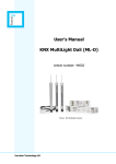
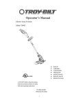
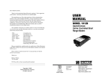
INSTALLATION GUIDE
AND USER MANUAL
CALI Avanti
Thermodynamic fluid filled electric radiator
With integral 7-Day LCD Programmer
By
Intelligent Heating Solutions
1
Please ensure that these instructions and guidelines are fully
understood and adhered to when installing and using this appliance.
TABLE OF CONTENTS
PAGE 3
PLEASE PAY SPECIAL ATTENTION
PAGE 4
BATHROOM/SPLASH AREAS INSTALLATION GUIDELINES
PAGE 5
WALL MOUNTING GUIDELINES
PAGE 6
ELECTRICAL INSTALLATION GUIDELINES
PAGE 7
PROGRAMMER DESCRIPTION
PAGE 8
PROGRAMMER FUNCTIONS / SETTINGS
PAGE 9
PROGRAMMER FUNCTIONS / SETTINGS
PAGE 10
WARRANTY / PURCHASE DETAILS
PAGE 11
PROVISION FOR USER NOTES
PAGE 12
INTELLI HEAT COMPANY DETAILS
With Intelligent Thermostat &
Seven Day LCD Programmer
Intelligent Heating Solutions
2
This product is safe and water resistant. Nevertheless, do not touch the radiator or
the thermostat when any part of you is wet. This product is for interior use only.
Ensure turned off at the main power source, and clean with a soft, non
abrasive damp cloth. Never allow water to splash onto any part of the appliance.
Do not lay any material over the radiator, especially if it is damp or wet. Never place
any object against the radiator. Always ensure that the radiator is installed in an open
area to allow the warmth to be radiated and not where curtains will be drawn over it.
Although this product is designed to ensure safety and ease of use, like with any other
electrical or heating product, always exercise caution where children are concerned.
We strongly advise you not to allow children or any unsuitable person to operate the
controls or to tamper with any electrical connection.
Never pull, sit on, hang from or load the radiator with any weight. Such practice may
damage the radiator or cause it to come loose from the wall or the wall fitting
attachments, which could cause serious injury. Also, to avoid such injury, check from
time to time to ensure that the radiator is securely fixed to the wall.
Never attempt to alter or modify this product, paint it, or apply stickers. This will
invalidate the warranty and may cause the product to malfunction or personal injury.
Connect the BLACK WIRE to any EARTH, LIVE or NEUTRAL terminal. The black wire must only
be used for connection to an external Pilot-Wire Programmer. Connection of the black wire to any other
terminal will destroy the thermostat. If the black wire is not used for connection to a Pilot-Wire
programmer, it must be properly insulated and isolated. This appliance is Double Insulated, therefore
it must not be Earthed. The cable contains: (BROWN: Live) (GREY/BLUE: Neutral) (BLACK: the Signal Wire).
1.
INTELLI HEAT Ltd or any associated company or person cannot be held responsible for any fault, damage, or personal
injury caused if these instructions have not been fully adhered to, or where non-original materials or accessories
have been used. Non observance to these guidelines and all applicable regulations may invalidate the warranty.
2.
This radiator is filled with a special Thermodynamic Fluid. Any repair involving opening the access to this fluid must
be carried out by an electrician approved by the manufacturer. The manufacturer must be contacted in the unlikely
event of any leakage of this fluid. Please note that all regulations for the disposal of heating fluid and electrical
appliances must be fully adhered to.
3.
If the cable or any other electrical part fails or becomes damaged, repair or replacement must be carried out by an
electrician approved by the manufacturer, or by a suitably qualified, experienced electrician familiar with such
products who has the necessary instructions.
4.
This product must not be positioned below an electrical socket and all applicable regulations relating to the
installation of electrical appliances must be fully adhered to. See pages 4 & 6 for further information and guidance.
5.
During operation, it is normal for the radiator to make minor clicking sounds due to metal expansion/contraction,
and for one end fin, or one each side not to heat up, this allows the flow and expansion of the thermodynamic fluid.
3
Therefore,
connection to Earth is prohibited. The cable contains the
following colour coded wires: (BROWN = LIVE/LINE)
(GREY or BLUE = NEUTRAL) (BLACK = PILOT WIRE). The
black wire is a signal wire for connection to an external
pilot wire programmer, do not connect it to any EARTH,
LIVE or NEUTRAL terminal, this will at some time destroy
the thermostat. If not used, it must be properly insulated.
CL
x
x
x
x
x
IP24
Double
Doubleinsulated
insulated
Double insulated
IP24 Rated - only install outside Zone 2
The following information is a guide to help you understand where this radiator can and cannot be placed,
with special regard to bathrooms and any other potential ‘splash’ area such as a kitchen. This is not an
installation guide, therefore, for complete assurance reference should be made to the IEE Wiring Regulations
17th Edition (or the most recent Edition/amendments in place when installing this product), or a qualified
electrician. Bathrooms and potential splash areas are considered to be 'special locations' for electrical
installations because they have an increased risk of electric shock for the users, due to the proximity of water.
Firstly, it is important to understand the rating by which electrical appliances are classified. IP stands for
Ingress Protection, and relates to the standard EN 60529 - an international classification system for the
sealing effectiveness of enclosures of electrical equipment against the intrusion into the equipment of
foreign bodies (such as dust, fingers, tools) and moisture. This classification uses the letters IP followed by
two, or occasionally three further digits, and this indicates the degree of protection provided. The higher the
number, the greater the protection. The first digit relates to the degree that persons are protected against
contact with moving parts that could prove hazardous, and also the degree that equipment is protected
against solid foreign bodies intruding into the unit. The second digit is the most relevant to electric radiators,
this indicates the degree of protection against the harmful entry of various forms of moisture.
The diagram above shows a bathroom split into three clear zones: 1, 2 and 3 (Zone 3 has been withdrawn
From the 17th Edition of the regulations). Zone ‘0’ is inside the bath or shower itself, any electrical fitting
installed in this zone must be rated at least IP67, which is total immersion proof.
This product is IP24 rated, If you intend to install this radiator in a bathroom or a potential splash area, to
ensure compliance with the current regulations and personal safety, it must be positioned outside zone 2.
In addition, installation must be compliant with the latest IEE regulations, which includes the stipulation that
the electric supply circuit of the radiator must be protected by a 30 mA RCD protected circuit, the opening
distance between the contacts must be greater than 3mm, and the circuit must be easily accessible. Briefly
explained, all electrical connections, switching and installation must be fully compliant with all current
regulations regarding the installation of electrical appliances in a bathroom or a potential splash area,
therefore, we strongly advise that only a qualified electrician should install this unit in such an area.
Power supply for single-phase current 230V ~ 50 Hz. The connection must be made in compliance with the
regulations in force; before connecting the electric resistance to the line, check the voltage and power values
indicated on the data plate.
4
Rawlplugs and Screws for fixing the mounting brackets to the wall are not included due
to the unknown construction of the wall that you intend to fix this heater to. It is essential that this
heater is mounted to the wall level and securely using the appropriate rawlplugs and screws. When
mounting the radiator, the top bracket arms slot between the last two vertical elements each side of the
radiator with the top and bottom horizontal element bars of the radiator resting on the bracket arms.
1
2
3
4
5
6
(B)
A
Wall brackets with securing clips
A
D
B
E
B
E
A to E - Measurements in millimetres
C
Floor
950
400
500
155
80
700
1200
555
500
235
80
700
1500
715
500
400
80
700
1800
950
500
480
80
700
CALI
Watts
Height mm
Floor
Specifications
Width mm
Depth mm
Weight Kg
Product Code
950
580
610
90
15
CAV 0950
1200
580
770
90
19
CAV 1200
1500
580
930
90
24
CAV 1500
1800
580
1090
90
29
CAV 1800
CL
IP24
Double
Doubleinsulated
insulated
The crossed-out wheeled-bin symbol reminds you that in the European Union all electrical and
electronic products and batteries must be taken to separate collection points at the end of their
working life. Do not dispose of this product as unsorted municipal waste. Take this product to
a collection point that prevents possible harm to the environment or human health from
uncontrolled waste disposal and to promote the sustainable reuse of material resources.
Collection information is available from waste authorities or national producer organizations.
Double insulated
Please take every safety precaution when lifting, moving,
and installing this product. We strongly advise that you are assisted when installing this product.
5
Therefore, connection to Earth is prohibited. The
cable contains the following colour-coded wires: (BROWN = LIVE/LINE) (GREY or BLUE = NEUTRAL) (BLACK =
PILOT WIRE). The black wire is a signal wire only to be used for connection to an external pilot wire
programmer, do not connect it to any EARTH, LIVE or NEUTRAL terminal, this will destroy the thermostat. If
the black pilot wire is not connect to an external pilot wire programmer, it must be properly insulated/isolated.
The power cable to this appliance is not supplied fitted with a plug. We recommend connection to a power
supply via a switched fused spur (13 amp). However, fitting a 3-pin 13 amp fused plug for connection to a
power supply via a power socket is also acceptable. Either way, do not connect the black wire to any terminal.
In most cases, this electrical appliance (one or several) does not need to be powered by a dedicated
circuit/power supply, therefore it/they can be connected to/powered by an existing 13 amp circuit/ring,
provided that, taking into consideration all other electrical appliances powered by that circuit, the combined
power loading (amps) on that circuit/ring is comfortably below the power supply (amps) to that circuit.
For any installation involving direct connection to a power source/electrical circuit, that electrical circuit must
be turned off from the main circuit breaker/fuse board before you start any such work. For example, but not
restricted to, connection by installing/connecting to a switched fused spur.
Although installation is usually very simple, it must comply with all applicable IEE Wiring Regulations 17th
Edition or the most recent IEE edition/any amendments in place when installing this product. If in doubt, you
must seek advice from, or commission a qualified electrician to install this unit.
If you intend to install this appliance in a bathroom or a potential splash area, RCD protection is essential
and the wiring, positioning and all electrical connections, switching and installation must be fully compliant
with all the regulations regarding installing electrical appliances in a bathrooms/potential splash areas (see
page 4 for further details). In such areas, to ensure full compliance with applicable regulations and personal
safety, you must seek advice from, or commission a qualified electrician to install this unit.
To prolong the life of all electrical components, turning this appliance on and off should be done using the
On/Standby button, not via the main power source/switch, this causes sudden jolts of power which are
harmful to the electrical components.
REPAIRS/ALTERATIONS
This product must not be altered or modified in any way. Any necessary repairs must only be undertaken by
an INTELLI HEAT approved electrician, or by an electrician with the full prior authorisation from INTELLI HEAT.
If the cable becomes damaged or needs extending, any repair, replacement or extending the cable must be
done by an INTELLI HEAT approved electrician, or by a qualified electrician familiar with such products. All
Instructions to be observed and the correct cable must be used (with pilot wire [black], live and neutral wires).
In the event of the programmer unit malfunctioning or becoming damaged, this entire unit must be replaced
by an original programmer unit supplied by INTELLI HEAT (no individual spare components are available).
CALI Avanti
CL
IP24
Double
Doubleinsulated
insulated
6
Double insulated
This programmer has four buttons and a display (Fig.1). The ON/Stand-by button switches the
regulator ON or puts it on standby. When on standby, the display shows a flashing dot, while when it is ON,
the display shows the time and program in the Chrono mode, or the temperature setting in the other modes.
Fig. 1
Fig. 2
Display
Mode Icon - as set
Thermometer symbol
Function button
ON/Standby button
Plus scroll button
Minus scroll button
This programmer has six modes: Radio (for RF models
only), Chrono, Pilot wire, Comfort, Night and Antifreeze.
To change the current mode, press the FUNCTION button.
ICON
MODE
DESCRIPTION / FUNCTION
RADIO
Set for receipt of radio signal commands/settings from a wireless central control unit
(not applicable to this product). All the pilot wire commands except STOP are disabled.
SIGNAL
CHRONO
(CLOCK)
This mode to be set to enable seven-day programming. Shows the weekly and hourly
programming schedule at two temperature levels (Comfort/high and low/night) as set
by the user. All the pilot wire commands except STOP are disabled.
PILOT WIRE
Programming and all settings will depend on the Pilot-wire programmer. Operates to
six commands: Comfort, Reduction = high temperature - 3.5° C, Stop, Frost Protection
= 7° C, Eco 1 = High Temperature - 1° C and Eco 2 = High Temperature - 2° C.
COMFORT
The ambient comfort temperature will correspond with the temperature set by the user.
Unlimited time regulation to the high temperature. All Pilot-wire commands except
STOP are disabled.
REDUCTION
(NIGHT MODE)
FROST
PROTECTION
Night temperature reduction mode (or can also be used as a background temperature
setting). Enables unlimited time regulation to maintain a comfortable temperature with
minimum energy consumption. All Pilot-wire commands except STOP are disabled.
Unlimited time regulation fixed at 7° C for protection against freezing / frost damage.
The heater comes on automatically when the ambient temperature drops lower than 7°
C. All Pilot-wire commands except STOP are disabled.
7
Temperature settings are at two different levels: 1) High temperature is used by the Chrono, Pilot wire and
Comfort modes (20 - 21°C). 2) Low temperature is used by the Night mode (Background). The activated
temperature level can be modified by the + and - buttons. Thermometer symbol flashes when modification
is taking place, please wait until the symbol stops flashing, which confirms the modified temperature is set.
Changes in ambient temperature are normal with electronic thermostats when there are
variations in the power required or when conditions outside the room change. The setting is appropriate only
for radiators installed in standard environments. It is normal for the regulator setting to be different to
achieve the same temperature in two separate places (effect of the surrounding environment). The Chrono
mode uses the temperature levels as shown in fig. 3 below.
Fig. 3
This option can be used to block/lock the buttons so that they cannot be used, which prevents inadvertent
setting changes or tampering by unauthorized persons and children. To lock, hold down the + and – buttons
simultaneously for at least 3 seconds. The padlock icon will appear to confirm that control access is blocked.
Fig. 4
Lock Icon
To unlock controls, again press the
+ and – buttons simultaneously for
at least 3 seconds, the lock symbol
will disappear allowing full access.
Firstly, select the Chrono mode by pressing the Function button. Each time the function button is pressed
the function mode will change, indicated by the mode symbol at the top left side of the screen. When the
Chrono mode has been selected/set (clock symbol), hold down the ON/standby and function buttons
simultaneously for at least 3 seconds. The hour digits begin to flash. Use + and – buttons to set the current
hour and confirm by pressing the function button. Set the minutes and day in the same way. The day is
marked by a dot on the vertical numbered scale, see fig. 5 below.
Fig. 5
Chrono mode Icon
Dot indicating day of week
7 Day week reference
Time setting bar
8
After setting the time and day, go on to weekly programming. Set a sequence for each hour and each day of
the week. Use the + and – buttons to make selections. The + button indicates high temperature regulation
for that time and the – button indicates low temperature regulation. The segments on the time setting bar
correspond to high temperature and the empty space corresponds to low temperature (see fig. 6). Press the
function button to save the day’s settings, then start the same procedure for the next day. When each day’s
timings and temperatures have been set for a complete seven day cycle (ensure the function button is
pressed after making each setting to save it) the screen will show the time, program and the chrono symbol.
Fig. 6
- - - - - - + + + + - - - - - - - + + ++ +
+
Firstly, select the Comfort mode by pressing the Function button until the Sun symbol appears, see fig. 7.
The thermostat/radiator can then be
set to reach/maintain your required
ambient temperature by pressing
the plus and minus buttons to raise
or lower the temperature setting.
Comfort Mode Icon
Thermometer symbol
At regular periods, check the condition of the programmer and make sure the buttons and
the display work properly. Push the buttons to select the modes as described on pages 7, 8 and 9.
Use only a clean, soft dry cloth to clean the programmer. Hold the programmer steady with one
hand whilst cleaning it using your other hand by making small round movements with the cloth, do not apply
pressure.
If the programmer seems to work correctly but the radiator is not heating at all, this may
indicate possible cutting in of the protection devices in the heating element. If the display shows “ErrS”, the
temperature sensor is damaged or the temperature is outside operating limits.
In the event of the programmer unit malfunctioning or becoming damaged, this entire unit
must be replaced (no spare components available) by an original programmer unit supplied by the
manufacturer. Any such work must be carried out by an electrician approved by the manufacturer, or by a
suitably qualified, experienced electrician familiar with such products who has the necessary instructions.
Electrical tests according to CEI EN 60335-1:2002, +A1:2004, EN 60335-2-30:2003, CEI
EN 55014-1:2000 +A1:2001 +A2:2002, EN 61000-3-2:2000, EN 61000-3-3:1995 +A1:2001, EN 55014-2:1997 +A1:2001,
EN 50366:2003. Applicable directives: RoHS Directive, 2006/95/CE Low Voltage Directive and 2004/108/CE Directive EMC
9
This product includes a free warranty covering five years for the body and two years for the electronics.
This warranty starts from your delivery date/receipt of the product and covers any miss-function that
may arise due to the faulty manufacture of the product. It does not cover any fault caused by miss-use
or damage caused by the purchaser or other persons, or incorrect installation, or non compliance with
these instructions after delivery/receipt. This warranty exclusively covers the repair or replacement free
of charge of parts/the product, or if necessary, full product replacement recognized as being faulty.
INTELLI HEAT Ltd cannot be held responsible to undertake disassembly and assembly works or to
refund any expenses incurred for such works, or for any direct or indirect damage to persons or
property due to any miss-functioning of the product. Please ensure that you keep all documentation
and invoice relating to this product as this will be required should you need to use this warranty. Thank
you for choosing an INTELLI HEAT product and we wish you a lasting and enjoyable use of this product.
Intelligent Heating Solutions
PLEASE ENSURE THAT YOU KEEP A RECORD OF THESE DETAILS
Date of purchase: ____________________________________________________________________
Date goods received: _________________________________________________________________
Model/s purchased: __________________________________________________________________
SUPPLIER DETAILS
Company / Supplier name: ___________________________________________________________
Telephone numbers: __________________________________________________________________
Email address: _______________________________________________________________________
Contact name: _______________________________________________________________________
INSTALLER DETAILS
Date of installation: __________________________________________________________________
Company / Trading name: ____________________________________________________________
Telephone numbers: _______________________________________________________________
Email address: _______________________________________________________________________
Contact name: _______________________________________________________________________
10
11
Intelligent Heating Solutions
INTELLI HEAT Ltd
Company Registration Number 05950029
Unit 18 Napier Place
Stephenson Way, Thetford
Norfolk IP24 3RL
www.intelligentheat.co.uk
E: [email protected]
www.intelligentheat.co.uk/support
ISSUE REFERENCE: CAV/MANUAL/01/3/1/12
12