1
GertDuino Board
Exclusively From
User Manual
By: G.J. van Loo, Version 1.4
Dated: 6th Nov 2013
1|Page
1
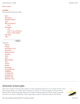
Con t e n ts
Cont ent s .......................................................................................................................... 2
1 I n t r odu ct ion ........................................................................................................................................ 3
2
3
4
5
1.1
I dent ify ......................................................................................................................................... 3
1.2
Com parison ................................................................................................................................. 4
1.3
Vext ............................................................................................................................................... 4
RS2 3 2 / UART .................................................................................................................................... 4
2.1
At m ega- 328 & Pi UART ........................................................................................................... 5
2.2
At m ega- 48 UART....................................................................................................................... 5
At m e ga - 3 2 8 ..................................................................................................................................... 6
3.1
Feat ures ....................................................................................................................................... 6
3.2
Program t he At m ega- 328 ....................................................................................................... 6
3.3
Using/ running t he At m ega-328 ............................................................................................ 7
At m e ga - 4 8 ........................................................................................................................................ 7
4.1
Feat ures ....................................................................................................................................... 7
4.2
Program t he At m ega- 48 ......................................................................................................... 7
4.3
Using/ running t he At m ega-48 ............................................................................................... 8
4.4
Real Tim e Cloc ........................................................................................................................... 8
4.5
I nfra- red receiver/ rem ot e cont rol receiver ....................................................................... 8
4.6
Bat t ery Drain .............................................................................................................................. 9
4.7
At m ega- 48 LED t rick .............................................................................................................. 10
Con n ect ors ...................................................................................................................................... 11
5.1
Alt ernat e funct ions. ................................................................................................................ 11
5.2
At m ega- 328 .............................................................................................................................. 13
5.3
At m ega- 48 ................................................................................................................................ 14
5.4
Raspberry- Pi ............................................................................................................................. 15
6
Fr e qu e n t ly Ask e d Qu e st ion s ( FAQs) .................................................................................. 16
7
H ow t o st a r t ................................................................................................................................... 17
8
9
7.1
On t he Raspberry- Pi: ............................................................................................................. 17
7.2
On a PC ...................................................................................................................................... 17
Ex a m ple pr ogr a m s ...................................................................................................................... 19
8.1
At m ega- 328 .............................................................................................................................. 19
8.2
At m ega- 48 ................................................................................................................................ 23
Con t r ol Ar du in o Re se t ............................................................................................................. 265
10 Appe n dix A : Ge r t Du in o Sch e m a t ic ..................................................................................... 26
2|Page
1 I n t r odu ct ion
The Gert Duino is a Raspberry- Pi add- on board which offers t he sam e funct ionalit y as an
Arduino- Uno but wit h som e ext ra added feat ures.
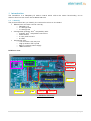
1 .1 I de n t ify
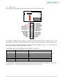
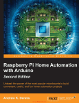
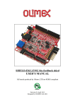
The pict ure below let s you ident ify t he various funct ions on t he board.
• RS232 level convert er can be used by:
o Raspberry- Pi
o or At m ega-328
o or At m ega-48
• At m ega 328 (Arduino- Uno ® com pat ible) wit h:
o Arduino- Uno ® com pat ible connect ors
o Reset but t on
o 2 user push but t ons
o 6 LEDs.
• At m ega 48 wit h:
o I / O connect or wit h 20 pins.
o High precision RTC cryst al
o Bat t ery backup power supply
o I RDA int erface
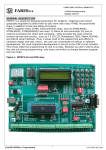
PCB Ove r vie w :
R232
Jumpers
IRDA receiver
Battery for RTC
Atmega 48
Atmega 328
2 user buttons
6 LEDS
More I/O
Reset button
RTC X-tal
Pict ure
1: Gert Duino Funct ions
3|Page
1 .2 Com pa r ison
There are som e differences bet ween a norm al Arduino- Uno and t he Gert Duino.
Fu n ct ion
USB
Reset but t on
Power supply
3V3 supply
LED's
User pushbut t ons
RS232 buffer
Real- Tim e- Clock
I nfra- red int erface
Ar du ino- Uno
Slave int erface
Yes
7..12V, ~ 250m A
~ 50m A
One Not - buffered
-
Ge r t Du in o
Yes
< 5V Raspberry- Pi>
~ 150m A.
Six Buffered
Two
Yes
Yes
Yes
Table 1: Com parison Gert Duino vs Arduino- Uno
1 .3 Ve x t
As t he board does not have a separat e supply t he Vext is not connect ed. I f you want it
connect ed you have t o add t he following com ponent s:
J1, L4 ( or a short inst ead of L4) , D20 ( or a short inst ead of D20) .
2
RS2 3 2 / UART
The Gerduino board has a RS232 level convert er which will convert t he signals form a UART t o
t he RS232 st andard volt ages ( And invert t hem as per t hat sam e st andard) . The RS232 signals
com e from J12.
Pin 3 is t he receive
Pin 2 is t he t ransm it
Pin 1 is t he ground
4|Page
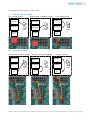
Connect ions can be m ade in m any ways:
2 .1 At m e ga - 3 2 8 & Pi UART
Pi t o RS232 buffers
At m ega-328 t o RS232 buffers
Raspberry-Pi
Atmega 328
Atmega 328
RS232
buffers
Atmega
48
2 .2
Raspberry-Pi
Raspberry-Pi
Atmega 328
Pi t o At m ega-328
RS232
buffers
RS232
buffers
Atmega
48
Atmega
48
At m e ga - 4 8 UART
At m ega- 48 t o RS232 buffers
Raspberry-Pi
At m ega- 48 t o At m ega- 328
Atmega 328
Atmega 328
RS232
buffers
Atmega
48
Raspberry-Pi
Raspberry-Pi
Atmega 328
At m ega- 48 t o Pi
RS232
buffers
RS232
buffers
Atmega
48
Atmega
48
5|Page
3
3 .1
At m e ga - 3 2 8
Fe a t u r es
This device is com pat ible wit h t he Arduino Uno. I n cont rast t o t he 328 on t he GERTBOARD t his
device runs of 5V, has t he 16MHz oscillat or and has connect ors which are 100% Arduino- Uno
com pat ible. I t also cont ains t he reset swit ch.
This board also has t he following com ponent s which you will n ot find on t he Uno:
• 2 User push but t ons
• 6 LEDs 1
LEDs
One LED is connect ed t o PB5 ( aka Port -13 aka SCK) . This is com pat ible wit h t he UNO. The
Gert Duino has a five m ore LEDs. The t ot al list of LEDs is:
- PB5 ( Port -13)
- PB1 ( Port -9)
- PB2 ( Port -10)
- PD3 ( Port - 3)
- PD5 ( Port - 5)
- PD6 ( Port - 6)
The LEDs are not direct ly connect ed but are buffered and t hus do not give any significant load
on t he signal pins.
Use r bu t t on s
The t wo user but t ons are connect ed t o pins PC2 and PC3. They will only funct ion correct ly if t he
pins have an int ernal or ext ernal pull-up. The but t on are connect ed t hrough a 1K Ohm resist or
so t hey will not cause a short if a pin is set as out put and t he but t on is pressed.
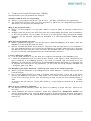
3 .2 Pr ogr a m th e At m e ga - 3 2 8
To program t his device from t he Raspberry - Pi you have t o place t he following 4 jum pers:
Then run t he script Program 328as described in sect ion 8.1.At m ega-328.
To program t he 328 using a JTAG- I CE you need t o use t he "squid" cable and m ake t he following
connect ions:
1
LED: The first debug tool any programmer grabs for.
6|Page
At t he left t here are t he GND ( whit e) and 5V ( Purple) connect ions.
At t he t op row right are t he Reset ( green) , Mosi ( Red) , Clk ( Black) and Miso (Grey) 2 .
The equivalent JTAG nam es for t hese are: nSRST, TDI , TCK, TDO
3 .3 Usin g/ r un n in g t h e At m e ga - 3 2 8
When t he device has been program m ed it will run t hat program independent of t he RaspberryPi. I n fact you can rem ove t he board from t he Raspberry - Pi and use it st andalone.
When developing program s you m ay leave t he jum pers in place as t he program m e will t ri- st at e
it s pins and set t he reset pin high when it has finished. This is NOT t he case if t he PI is reset or
not powered. Especially t he reset - j um per needs t o be rem oved ot herwise t he Raspberry- Pi GPI O
pin 8 ( which is default low ) will t he keep t he 328 device in reset or you can run t he reset _off
script .
You should also rem ove t he jum pers if you want t o use any of t he following pins: B3,B4,B5,C6.
4
At m e ga - 4 8
4 .1 Fe a t u r es
This device is int ended t o be used as Real Tim e Clock ( RTC) and/ or as I RDA front end. However
it is also freely program m able by t he user and t hus can be used for any ot her applicat ion, giving
t he user t he power of not one but TWO At m ega devices t o play wit h.
N ot e: The I 2C int erface of t he At m ega-48 is connect ed perm anent ly t o t he Raspberry- Pi I 2C
int erface < GOI O0/ 1 on rev1, GPI O 2/ 3 on rev2> .
Also beware t hat if you m ake program m ing errors wit h t he At m ege- 328 t he device can easily be
replaced. This is not t he case wit h t he At m ega- 48. I t is t herefore st rongly recom m ended t hat
you are ext ra careful and do not dam age any of t he I / O port s.
Spa r e con ne ct ion s.
The following I / O pins of t he At m ega- 48 are not used and are brought out t o a connect or:
B0,B1,B2, B3, B4,B5, C0,C1,C2,C3,D0,D1,D4, D5, D6, D7.
Beware t hat B3, B4 and B5 are also used for program m ing t he device.
4 .2 Pr ogr a m th e At m e ga - 4 8
To program t he At m ega-48 from t he Raspberry-Pi you have t o place t he following 4 jum pers:
The program m ing is t he sam e as t he 328 but replace "328p" wit h "48pa".
2
The colours used here are the same as on MY squid cable but I can't guarantee all squid cables are the same.
7|Page
To program t he 48 using a JTAG-I CE you need t o use t he "squid" cable and m ake t he following
connect ions:
4 .3
At t he left t here are t he GND ( whit e) and 5V ( Purple) connect ions.
At t he bot t om row right are t he Reset ( green) , Mosi ( Red) , Clk ( Black) and Miso ( Grey) . 3
The equivalent JTAG nam es for t hese are: nSRST, TDI , TCK, TDO
Usin g/ r un n in g t h e At m e ga - 4 8
What was writ t en about t he 328 also is valid for t he 48: when t he device has been program m ed
it will run t hat program independent of t he Raspberry - Pi. I n fact you can rem ove t he board from
t he Raspberry- Pi and use it st andalone.
When developing program s you m ay leave t he jum pers in place as t he program m e will t ri- st at e
it s pins and set t he reset pin high when it has finished. This is NOT t he case if t he PI is reset or
not powered. Especially t he reset - j um per needs t o be rem oved ot herwise t he Raspberry - Pi GPI O
pin 8 ( which is default low ) will t he keep t he 48 device in reset or you can run t he reset _off
script .
You should also rem ove t he jum pers if you want t o use any of t he following pins: B3,B4,B5,C6.
4 .4 Re a l Tim e Clock
The At m ege-48 device has a 32768Hz cryst al connect ed t o operat e as a Real- Tim e- Clock ( RTC) .
Exam ple code for t his can be found under sect ion 8 .2 At m e ga - 4 8 . The Cryst al is a high qualit y
t ype and under norm al condit ions a deviat ion is less t han 1 sec/ 3 days.
The ot her part of t he RTC is t hat t he At m ega-48 has a 3V bat t ery. I t will swit ch t o t hat bat t ery
when t he 5V power is rem oved. As t he At m ega- 48 is a fully program m ed m icrocont roller it can
be set -up t o perform ot her operat ions or hold ot her dat a when t he m ain power of t he BCM2835
is rem oved.
I f you have program m ed t he At m ege-48 correct ly it uses ~ 1µA when powered down.
4 .5 I n fr a - r e d r ece ive r/ r e m ot e con t rol r e ce ive r
The BCM2835 does not have a nat ive I RDA int erface. The prot ocol can be im plem ent ed using a
st andard GPI O pin but t hat put s a very heavy burden on t he CPU. To support I RDA t he At m ega48 has a TSSOP4038 I RD device connect ed t o pin D3. This device support s t he m ost com m on
I RDA prot ocol: 38KHz I R signal.
Unfort unat ely we could not run t he I RDA int erface from t he bat t ery as it uses t oo m uch current
( ~ 450 µA) . Thus you need t he 5V present for it t o operat e.
3
The colours used here are the same as on MY squid cable but I can't guarantee all squid cables are the same.
8|Page
The I RDA can also be used if t he Gert Duino is used st and- alone t o cont rol t he connect ed logic
using a rem ot e cont rol.
Not e t hat 95% of all TV/ Video/ CD rem ot e cont rols use t he 38KHz infra-red signal, but t he
coding varies great ly from t ype t o t ype.
4 .6 Ba t t e r y D ra in
I f a bat t ery is present and t he power of t he Raspberry- Pi is swit ched of t he At m ega- 48 will st ill
rem ain powered by t he Bat t ery. I t will also keep running. Unless t he bat t ery is rem oved or t he
At m ega- 48 is program m ed t o go int o a special ult ra- low- power condit ion, t he bat t ery will be
drained in a short t im e.
Even if you t hink t he device is in ult ra- low- power m ode it can st ill consum e power if it has t o
drive out put s high.
Measurem ent s have also show t hat if a UART connect ion exist s bet ween t he At m ega- 48 t o t he
Raspberry- Pi (even if it is not used) t hat increases t he lower power current from 1µA t o about
100µA.
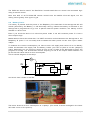
To m easure t he current consum pt ion you have t o use a 3V supply and connect it t o t he bat t ery
holder but bet ween t he supply and t he bat t ery holder you have t o place a current (Am pere)
m et er. Opt ionally you can connect a scope on one of t he I / O pins of t he At m ege48 t o see if t he
program is running. You should NOT connect anyt hing t o one of t he out put which loads an I / O
pin as t hat will cause ext ra current consum pt ion.
This is a block diagram of t he set up:
A
Gertduino
3V
Atmega48pa
GND
And t his is how it looks in real life:
The m et er shows a current consum pt ion of 1.3µAm p. ( The m et er is shown enlarged in t he lower
left hand corner of t he pict ure) .
9|Page
I f possible lim it t he current from your power source t o a few m illi- am ps. I m anaged t o blow a
fuse of m y m et er perform ing t he m easurem ent s because I accident ally short ed t he supply when
placing t he probe on t he bat t ery holder.
4 .7 At m e ga - 4 8 LED t r ick
I f you are debugging, an LEDs is oft en t he first t ool you reach for. But t he At m ega-48 does not
have any LEDs. However t he At m ega- 328 does! There are t wo ways in which you can use t hese
LEDs :
•
•
The safest way is t o rem ove t he 328 from it s socket .
The second way is t o erase t he 328 so t hat all it s pins are input s.
You can t hen use t he connect ors t o feed a signal t o an LED. Sim plest way is t o use a fem alem ale st rap bet ween connect or J10 and e.g. pins, 2,3 or 6 of J14.
10 | P a g e
5
Con n e ct or s
The board cont ains a num ber of connect ors. You will find t hat in t he docum ent t he connect ors of
t he At m ega devices have t wo ways of num bering: There are t he single num bers 0..13 and
A1..A3. These are t he num bers used in m any Arduino exam ple program s. Alongside t hose I use
t he official pin nam es ( PB0..PB7, PD0..PD7, PCO..PC3) . The lat t er are easier t o use if you have
t o work wit h t he AVR dat asheet .
5 .1 Alt e r na t e fun ct ion s.
The At m ega-328 and t he At em ege-48 have exact ly t he sam e pins wit h t he sam e funct ionalit y.
The devices only differ in t he size of t heir various m em ories. The following is a t able of t he pins
and all t he funct ions t hey can carry. These where copied from t he AVR dat asheet . For det ails of
t he funct ions you should read t hat dat asheet .
#
-
Nam e
PB7
Fu n ct ion s
XTAL2 ( Chip Clock Oscillat or pin 2)
TOSC2 ( Tim er Oscillat or pin 2)
PCI NT7 ( Pin Change I nt errupt 7)
XTAL1 ( Chip Clock Oscillat or pin 1 or Ext ernal clock input )
TOSC1 ( Tim er Oscillat or pin 1)
PCI NT6 ( Pin Change I nt errupt 6)
-
PB6
13
PB5
12
PB4
11
PB3
10
PB2
SS (SPI Bus Mast er Slave select )
OC1B ( Tim er/ Count er1 Out put Com pare Mat ch B Out put )
PCI NT2 ( Pin Change I nt errupt 2)
9
PB1
OC1A ( Tim er/ Count er1 Out put Com pare Mat ch A Out put )
PCI NT1 ( Pin Change I nt errupt 1)
8
PB0
I CP1 (Tim er/ Count er1 I nput Capt ure I nput )
CLKO ( Divided Syst em Clock Out put )
PCI NT0 ( Pin Change I nt errupt 0)
SCK (SPI Bus Mast er clock I nput )
PCI NT5 ( Pin Change I nt errupt 5)
MI SO ( SPI Bus Mast er I nput / Slave Out put )
PCI NT4 ( Pin Change I nt errupt 4)
MOSI ( SPI Bus Mast er Out put / Slave I nput )
OC2A ( Tim er/ Count er2 Out put Com pare Mat ch A Out put )
PCI NT3 ( Pin Change I nt errupt 3)
11 | P a g e
#
Nam e
Fu n ct ion s
ADC5 (ADC I nput Channel 5)
SCL ( 2- wire Serial Bus Clock Line)
PCI NT13 ( Pin Change I nt errupt 13)
ADC4 (ADC I nput Channel 4)
SDA (2- wire Serial Bus Dat a I nput / Out put Line)
PCI NT12 ( Pin Change I nt errupt 12)
ADC3 (ADC I nput Channel 3)
PCI NT11 ( Pin Change I nt errupt 11)
ADC2 (ADC I nput Channel 2)
PCI NT10 ( Pin Change I nt errupt 10)
ADC1 (ADC I nput Channel 1)
PCI NT9 ( Pin Change I nt errupt 9)
ADC0 (ADC I nput Channel 0)
PCI NT8 ( Pin Change I nt errupt 8)
A5
PC5
A4
PC4
A3
PC3
A2
PC2
A1
PC1
A0
PC0
#
Nam e
7
PD7
6
PD6
5
PD5
T1 (Tim er/ Count er 1 Ext ernal Count er I nput )
OC0B ( Tim er/ Count er0 Out put Com pare Mat ch B Out put )
PCI NT21 ( Pin Change I nt errupt 21)
4
PD4
3
PD3
XCK ( USART Ext ernal Clock I nput / Out put )
T0 (Tim er/ Count er 0 Ext ernal Count er I nput )
PCI NT20 ( Pin Change I nt errupt 20)
I NT1 ( Ext ernal I nt errupt 1 I nput )
OC2B ( Tim er/ Count er2 Out put Com pare Mat ch B Out put )
PCI NT19 ( Pin Change I nt errupt 19)
2
PD2
1
PD1
0
PD0
Fu n ct ion s
AI N1 ( Analog Com parat or Negat ive I nput )
PCI NT23 ( Pin Change I nt errupt 23)
AI N0 ( Analog Com parat or Posit ive I nput )
OC0A ( Tim er/ Count er0 Out put Com pare Mat ch A Out put )
PCI NT22 ( Pin Change I nt errupt 22)
I NT0 ( Ext ernal I nt errupt 0 I nput )
PCI NT18 ( Pin Change I nt errupt 18)
TXD (USART Out put Pin)
PCI NT17 ( Pin Change I nt errupt 17)
RXD ( USART I nput Pin)
PCI NT16 ( Pin Change I nt errupt 16)
12 | P a g e
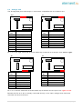
5 .2 At m e ga - 3 2 8
The At m ega-328 pins are brought t o connect ors com pat ible wit h t he Arduino- Uno.
J1 4
J7
1
1
1
1
1
1
1
1
1
1
1
1
1
1
Pin
N o.
10
9
8
7
6
5
4
3
2
1
1
1
1
Sign a l
Pin
N o.
8
7
6
5
4
3
2
1
A5/ PC5/ SCL
A4/ PC4/ SDA
AREF
Ground
13/ PB5/ SCK/ LED 0
12/ PB4/ MI SO
11/ PB3/ MOSI
10/ PB2/ SS/ LED 2
9/ PB1/ PCI NT1/ LED 1
8/ PB0/ CLK0
1
Sign a l
7/ PD7/ AI N1
6/ PD6/ AI N0/ LED 6
5/ PD5/ T1/ LED5
4/ PD4/ T0
3/ PD3/ I NT1/ LED 4
2/ PD2/ I NT0
1/ PD1/ TXD
0/ PD0/ RXD
Pin 1 is on t he right -hand side so t hese t ables t op- t o- bot t om are t he pins from le ft - t o- r igh t .
J9
J6
1
1
1
1
1
1
1
1
1
1
1
1
1
1
1
Pin
N o.
8
7
6
5
4
3
2
1
1
Sign a l
NC
Ground
Ground
5V
3V3
Reset ( Act ive low)
5V
NC
1
Pin
N o.
6
5
4
3
2
1
1
Sign a l
A5/ PC5/ SCL
A4/ PC4/ SDA
A3/ PC3/ ADC3/ BUT1
A2/ PC2/ ADC2/ BUT0
A1/ PC1/ ADC1
A0/ PC0/ ADC0
Pin 1 is on t he left - hand side so t hese t ables t op- t o- bot t om are t he pins from r igh t - t o- left .
Beware t hat Pin 8 of J9 is norm ally connect ed direct ly t o t he input volt age which has been
rem oved and t hus is NC here.
13 | P a g e
5 .3 At m e ga - 4 8
All unused pin of t he At m ega-48 are brought out t o a 20 - pin connect or:
1
1
1
1
1
1
1
1
5V
VBAT/5V
ADC0/PC0 : A0
ADC1/PC1 : A1
ADC2/PC2 : A2
ADC3/PC3 : A3
RXD/PD0 : 0
TXD/PD1 : 1
T0/PD4 : 4
Ground
1
1
13 : PB5/SCK
12 : PB4/MISO
11 : PB3/MOSI
10 : PB2/SS
9 : PB1/PCINT1
8 : PB0/CLK0
7 : PD7/AIN1
6 : PD6/AIN0
5 : PD5/T1
Ground
20
The supply 5V/ VBAT which goes t o t he At m ega- 48 also goes t o t he connect or pin 3. Any
equipm ent connect ed t o t hat pin will also draw current from t he bat t ery if t he 5V is swit ched off.
The supply com es t hrough a Schot t ky diode so t he act ual volt age is lower: ~ 4.5 Volt s. Also t he
current consum pt ion should be lim it ed ~ 100m A.
The following pins of t he ATm ega- 48 are dedicat ed connect ed:
Pin
PD2
H a r d w ir e d t o
5V Supply
Fu n ct ion
Det ect absence of 5V supply (for RTC)
PD3
PC5
PC4
PB7
PB6
PC6
I RDA out put
SCL
SDA
XTAL1
XTAL2
Program reset
Receive I RDA signal
I 2 C connect ion wit h t he Pi
I 2 C connect ion wit h t he Pi
32768Hz Tuning cryst al
32768Hz Tuning cryst al
Reset when program m ing
The At m ege- 48 does not have a dedicat ed reset pin as t hat would int erfere wit h it s funct ion as
real-t im e- clock. A reset can be obt ained by pulling pin 4 of J13 low.
14 | P a g e
5 .4 Ra spbe rr y- Pi
All connect ions bet ween t he board and t he Raspberry- Pi are prot ect ed against 5V signals. The
I 2 C bus has FET level swit ches. All t he ot her signals use resist ive dividers.
The following connect ions of t he Raspberry- Pi are used:
5V
3V3 ( I 2 C level convert ers only)
GPI O0/ 2 ( I 2 C SDA)
GPI O1/ 3 ( I 2 C SCL)
The following connect ions of t he Raspberry- Pi are used if t he program m ing j um pers or UART
j um pers are placed:
GPI O14
GPI O15
GPI O8
GPI O9
GPI O10
GPI O11
( UART-Tx)
( UART- Rx)
( Reset )
( MI SO)
( MOSI )
( SCLK)
15 | P a g e
6
Fr e qu e n t ly Ask e d Qu e st ion s ( FAQs)
Som e quest ions you m ay ask and t he answers.
a vr du de : AVR de vice n ot r espon din g
Q: When I t ry t o program t he device I get an error: "avrdude: AVR device not responding."
A: The m ost likely cause is t hat you have forgot t en t o place t he four program m ing j um pers.
See sect ion 3.2 Program t he At m ega- 328.
W h y is m y pr ogr a m slow ?
Q: When I run t he program it is very slow. Where I expect a delay of 1second it t akes m uch
longer.
A: St raight from t he fact ory t he CPU runs from t he int ernal 8MHz clock and t hat is divided by
8. Thus t he processor runs at 1 MHz. To swit ch t o t he full speed, using t he ext ernal 16MHz
oscillat or run t he avrdude com m and as described in 8.1At m ega- 328under "I n it ia l clock
se t u p"
W h y doe s m y pr ogr a m n ot r u n ?
Q: When I upload t he program it runs fine but when I halt t he Raspberry- Pi or when I st art t he
Raspberry- Pi m y program does not work.
A: GPI O 8 cont rols t he Reset of t he Arduino. This pins m ust be high but for your program t o
run. The sim plest solut ion is t o rem ove t he program m ing jum pers. Alt ernat ive is t o program
t he GPI O- 8 pin high using t he reset _off script . The avrdude wit h t he -c gpio opt ion does t his
for you so norm ally aft er program m ing t he reset has been rem oved.
I h a ve a differ e n t com pile r
Q: I use t he AVR com piler on m y PC. How do I program t he At m ega on t he Raspberry - Pi?
A: I have only experience wit h t he GCC version (AVR 5.1 and higher) . Aft er com pilat ion you
find a .h e x file in t he de bu g direct ory. You have t o t ransfer t hat file som ehow t o t he
Raspberry- Pi and use t he program m er script Progr a m 3 2 8 as described in 8.1At m ega- 328
t o program t he device(s) on t he Gert Duino. ( I f you have t he script already inst alled use
"./ program _328 < hex file> )
Th e Ra spbe rr y- Pi boot s diffe re n t : it h a s big t e x t a n d n ot t h e nor m a l pr om pt !
Q: When I plug t he Gert Duino on t he Raspberry- Pi it boot s different : I t has big t ext and not t he
norm al prom pt !
A: Pin 5 of t he GPI O connect or is used t o indicat e ‘safe boot m ode’. I f t hat pin is low when
boot ing t he Raspberry- Pi boot s in “ safe m ode” . Pin 5 is also connect ed t o t he At m ge-48. I t
is one of t he I 2C pins. Thus if your 48 is driving a LOW on t hat pin t he Pi always boot s in
safe
m ode.
To prevent t his you can put “ avoid_safe_m ode= 1” in t he config.t xt file and t he pi will boot
norm ally.
W h y is t h e r e no ba t t e r y su pplie d
Q: The Gert Duino has a bat t ery holder but t here is no bat t ery in t here. Why do I have t o buy
m y own?
A: These bat t eries are lit hium bat t eries. Those are classified as ‘D a n ger ous Goods’ and
require special paper work, warning labels and ot her precaut ions when shipped. And t hat is
for shipping wit hin t he UK. I nt ernat ional shipping becom es a night m are. So we decided t o
leave it off.
16 | P a g e
7
H ow t o st a r t
Before you can program t he devices you need t o have a cross com piler. A cross com piler is a
com piler which runs on one t ype of processor, but generat es code for a different t ype. I n t his
case t he com piler runs on t he Raspberry- Pi (ARM11 device) but m akes code for t he At m el
devices.
7 .1 On t h e Ra spbe rr y- Pi:
When program m ing t he At m el devices on t he Raspberry- Pi you have t wo choices:
•
•
Use t he Arduino GUI
Use t he GCC At m el com piler
For bot h you need t o have a cross com piler for t he At m ega devices. Easiest is t o inst all t he
Arduino package:
sudo apt-get install arduino
a vr du de
You need t o use a program called "avrdude" t o program t he devices BUT you need a special
version of "avrdude" which can program t he devices using t he GPI O of t he Raspberry- Pi. Thanks
for Gordon Henderson ( proj ect s.drogon.net ) who has provided t hese:
St a n da r d De bia n Squ ee ze:
cd /tmp
wget http://project-downloads.drogon.net/gertboard/avrdude_5.10-4_armel.deb
sudo dpkg -i avrdude_5.10-4_armel.deb
sudo chmod 4755 /usr/bin/avrdude
D e bia n Raspbia n :
cd /tmp
wget http://project-downloads.drogon.net/gertboard/avrdude_5.10-4_armhf.deb
sudo dpkg -i avrdude_5.10-4_armhf.deb
sudo chmod 4755 /usr/bin/avrdude
You can now com pile program s for t he At m ega devices and upload t he program int o t he chip on
t he Gert Duino. Exam ple source code, Makefile and how t o upload t he program can all be found
in sect ion 8 Ex a m ple pr ogr a m s.
I f you want t o use t he Arduino developm ent environm ent you have t o adapt it . See
proj ect s.drogon.net / raspberry- pi/ gert board/ arduino- ide- inst allat ion-isp/ how t o do t hat .
7 .2
On a PC
At m el have a free C- com piler. You can get inform at ion about t he lat est version here:
ht t p: / / www.at m el.com / t ools/ ATMELSTUDI O.aspx
You can com pile on t he PC but you need t o t ransfer t he final .hex file t o t he Raspberry- Pi before
you can program t he At m ega devices.
17 | P a g e
Alt ernat ive is t hat you buy a JTAG-I CE box and use t hat t o program and t he devices but t hat is
a lot m ore expensive. I t does have t he advant age t hat you can use it for debugging as well:
St ep t hrough t he program , set breakpoint s ,inspect variables et c.
18 | P a g e
8
8 .1
Ex a m ple pr ogr a m s
At m e ga - 3 2 8
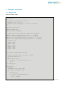
blin k .c sou rce code :
/*
* blink.c
*
* Created: 23/09/2013 21:04:02
* Author: G.J. van Loo
* Simple example program to 'walk' the LEDs
*/
#include <avr/io.h>
#define DELAY 250
#define F_CPU 16000000
// Some
#define
#define
#define
#define
//
//
//
//
//
//
//
macros that make the code more readable
output_low(port,pin) port &= ~(1<<pin)
output_high(port,pin) port |= (1<<pin)
set_input(portdir,pin) portdir &= ~(1<<pin)
set_output(portdir,pin) portdir |= (1<<pin)
Outputs are:
LED0 = PB5
LED1 = PB1
LED2 = PB2
LED3 = PD3
LED4 = PD5
LED5 = PD6
void delay_ms(unsigned int ms)
{
uint16_t delay_count = F_CPU / 17500;
volatile uint16_t i;
while (ms != 0) {
for (i=0; i != delay_count; i++);
ms--;
}
} // delay_ms
void delay()
{ long d;
unsigned char oldb,oldd;
for (d=0; d<DELAY; d++)
{
delay_ms(1);
if ((PINC & 0b00001000)==0)
{
oldb = PORTB;
19 | P a g e
oldd = PORTD;
PORTB = 0xFF;
PORTD = 0xFF;
delay_ms(1);
PORTB = oldb;
PORTD = oldd;
d--;
}
else
{ if ((PINC & 0b00000100)==0)
d--;
else
delay_ms(1);
}
// if button pressed
} // if button pressed
} // delay
int main(void)
{ // int b;
// Set all LED connections to output
DDRB = 0b00100110;
DDRD = 0b01101000;
PORTB = 0x00;
PORTD = 0x00;
// Set button (port C) to input
DDRC = 0b00000000;
// pull-up on C2 & C3:
PORTC = 0b00001100;
while(1)
{ // convoluted but simple walk the leds
output_high(PORTB,5);
delay();
output_low (PORTB,5);
output_high(PORTB,1);
delay();
output_low (PORTB,1);
output_high(PORTB,2);
delay();
output_low (PORTB,2);
output_high(PORTD,3);
delay();
output_low (PORTD,3);
output_high(PORTD,5);
delay();
output_low (PORTD,5);
output_high(PORTD,6);
delay();
output_low (PORTD,6);
output_high(PORTD,5);
delay();
output_low (PORTD,5);
output_high(PORTD,3);
delay();
output_low (PORTD,3);
output_high(PORTB,2);
20 | P a g e
delay();
output_low (PORTB,2);
output_high(PORTB,1);
delay();
output_low (PORTB,1);
} // forever
} // main
M a k e file
# Makefile:
#
Make the GertDuino m328p firmware.
#
# Copyright (c) 2013 Gordon Henderson <[email protected]>
#################################################################################
# This file is part of gertduino-m328:
#Software to run on the Atmega328p processor on the Gerduino board
#Can be used for the Atmega328p processor on the GERTBOARD as well
#
This is free software: you can redistribute it and/or modify
#
it under the terms of the GNU General Public License as published by
#
the Free Software Foundation, either version 3 of the License, or
#
(at your option) any later version.
#
#
This is distributed in the hope that it will be useful,
#
but WITHOUT ANY WARRANTY; without even the implied warranty of
#
MERCHANTABILITY or FITNESS FOR A PARTICULAR PURPOSE. See the
#
GNU General Public License for more details.
#
#
You should have received a copy of the GNU General Public License
#
along with this. If not, see <http://www.gnu.org/licenses/>.
#################################################################################
TARGET=blink
MCU=atmega328p
FREWQ=16000000
# Debug
#DEBUG
= -gstabs
# C flags
CC
= avr-gcc
#CFLAGS = $(DEBUG) -O3 -Wall -std=gnu99 -mmcu=$(MCU) -DF_CPU=$(FREWQ) $(INCLUDE)
CFLAGS = $(DEBUG) -O2 -mcall-prologues -Wall -std=gnu99 -mmcu=$(MCU) DF_CPU=$(FREWQ) $(INCLUDE)
LD
= avr-gcc
#LDFLAGS2=-Wl,-uvfprintf -lprintf_flt
LDFLAGS = -mmcu=$(MCU) $(DEBUG) $(LIBLOC) $(LDFLAGS2)
#LIBS
= -ldross -lm
SRC
=
$(TARGET).c
OBJ
=
$(SRC:.c=.o)
all:
$(TARGET).hex
$(TARGET).hex: $(TARGET).elf
@echo [hex] $<
21 | P a g e
@avr-objcopy -j .text -j .data -O ihex $(TARGET).elf $(TARGET).hex
$(TARGET).elf:
$(OBJ)
@echo [Link] $<
@$(LD) -o $@ $(OBJ) $(LDFLAGS) $(LIBS)
@avr-size $(TARGET).elf
# Generate .lst file rule
%.lst : %.o
@echo [lst] $<
@avr-objdump -h -S $<> $@
.c.o:
@echo [CC] $<
@$(CC) -c $(CFLAGS) $< -o $@
.PHONEY:
clean
clean:
rm -f *.o *.elf *.hex *.lst Makefile.bak *~
Pr ogr a m 3 2 8
#!/bin/bash
# script to program 328p device using AVRDUDE and a hex file
if [ "$1" == "" ]; then echo Missing argument
exit 1;
fi
# if ends in .hex use full argument
# otherwise add the .hex
ext=${1:${#1}-4}
if [ "$ext" == ".hex" ]; then
/usr/bin/avrdude -c gpio -p m328p $1 -Uflash:w:$1
else
/usr/bin/avrdude -c gpio -p m328p $1.hex -Uflash:w:$1.hex
fi
Save t he above code in a file called program _328 and t hen run " chm od 777 program _328". Use
./ program _328 < hex file> t o program t he At m ega device.
I n it ia l clock se tu p
avrdude -qq -c gpio -p atmega328p -U lock:w:0x3F:m
U lfuse:w:0xE7:m -U hfuse:w:0xD9:m
-U efuse:w:0x07:m -
You norm ally run t he above com m and when you get a brand new device. I t program s t he
At m ega328 t o use t he ext ernal 16MHz Cryst al.
22 | P a g e
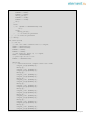
8 .2 At m e ga - 4 8
This sect ion shows an exam ple program for t he At m ega48. You will find t hat t he m akefile and
t he program m ing files are very sim ilar t o t he 328 exam ple.
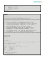
low _ pow e r .c sou rce code :
//
//
//
//
//
//
//
//
//
//
//
//
//
Example code which uses the 32767KHz
Crystal to implement a 1-second event
handler
Atmega Low power operation example
Using a 32768 Khz crystal on timer 2 and full power down mode
to implement a 1-second event handler
This code is written for the GCC compiler
Example for the GertDuino Atmega 48PA device
(This program will NOT run on the 328!)
This code is freeware
#include <avr/interrupt.h>
#include <avr/sleep.h>
volatile unsigned long count_seconds;
main()
{
// set PB0 as output
DDRB = 0xFE;
// Set-up 32 KHz oscillator
TIMSK2 = 0x00;
// No interrupts
ASSR
= 0x20;
// async run from xtal
TCNT2 = 0;
// clear counter
TCCR2B = 0x05;
// prescale 5=/128
// Wait for all 'busy' bits to be clear
// That happens on the first timer overflow
// which can take 8 seconds if you have a max pre-scaler!!
while (ASSR&0x07) ;
TIMSK2 = 0x01;
// overflow IRQ enable
count_seconds = 0; // clear seconds counter
sei();
//set the Global Interrupt Enable Bit
while (1)
{
SMCR = 0x7; // Go into lowest power sleep mode
asm("sleep");
asm("nop");
// Interrupt woke us up
// If we get here the interrupt routine has already been called
// Toggle LED on port B0 using LS timer bit
PORTB = count_seconds & 0x01;
}
} // main
//
23 | P a g e
// Timer 2 overflow
// if we set timer2 up correctly this routine is called every second
//
ISR(TIMER2_OVF_vect)
{ count_seconds++; // all we do here is count seconds elapsed
}
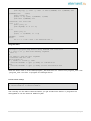
M a k e file:
# Makefile:
# Make the GertDuino m48p firmware.
#
# Copyright (c) 2013 Gordon Henderson <[email protected]>
###########################################################################
# This file is part of gertduino-m328:
#Software to run on the Atmega328p processor on the Gerduino board
#Can be used for the Atmega328p processor on the GERTBOARD as well
#
This is free software: you can redistribute it and/or modify
#
it under the terms of the GNU General Public License as published by
#
the Free Software Foundation, either version 3 of the License, or
#
(at your option) any later version.
#
#
This is distributed in the hope that it will be useful,
#
but WITHOUT ANY WARRANTY; without even the implied warranty of
#
MERCHANTABILITY or FITNESS FOR A PARTICULAR PURPOSE. See the
#
GNU General Public License for more details.
#
#
You should have received a copy of the GNU General Public License
#
along with this. If not, see <http://www.gnu.org/licenses/>.
###########################################################################
TARGET=low_power
MCU=atmega48p
FREWQ=1000000
# Debug
#DEBUG
= -gstabs
# C flags
CC
= avr-gcc
#CFLAGS
= $(DEBUG) -O3
-Wall -std=gnu99 -mmcu=$(MCU) DF_CPU=$(FREWQ) $(INCLUDE)
CFLAGS
= $(DEBUG) -O2 -mcall-prologues -Wall -std=gnu99 -mmcu=$(MCU) DF_CPU=$(FREWQ) $(INCLUDE)
LD
= avr-gcc
#LDFLAGS2=-Wl,-uvfprintf -lprintf_flt
LDFLAGS = -mmcu=$(MCU) $(DEBUG) $(LIBLOC) $(LDFLAGS2)
#LIBS
= -ldross -lm
SRC
=
$(TARGET).c
OBJ
=
$(SRC:.c=.o)
all:
$(TARGET).hex
$(TARGET).hex: $(TARGET).elf
@echo [hex] $<
@avr-objcopy -j .text -j .data -O ihex $(TARGET).elf $(TARGET).hex
24 | P a g e
$(TARGET).elf:
$(OBJ)
@echo [Link] $<
@$(LD) -o $@ $(OBJ) $(LDFLAGS) $(LIBS)
@avr-size $(TARGET).elf
# Generate .lst file rule
%.lst : %.o
@echo [lst] $<
@avr-objdump -h -S $<> $@
.c.o:
@echo [CC] $<
@$(CC) -c $(CFLAGS) $< -o $@
.PHONEY:
clean
clean:
rm -f *.o *.elf *.hex *.lst Makefile.bak *~
Pr ogr a m 4 8
#!/bin/bash
# script to program 48pa device using AVRDUDE and a hex file
if [ "$1" == "" ]; then
echo Missing argument
exit 1;
fi
# if ends in .hex use full argument
# otherwise add the .hex
ext=${1:${#1}-4}
if [ "$ext" == ".hex" ]; then
/usr/bin/avrdude -c gpio -p m48p $1 -Uflash:w:$1
else
/usr/bin/avrdude -c gpio -p m48p $1.hex -Uflash:w:$1.hex
fi
Save t he above code in a file called "program _48" and t hen run "chm od 777 program _48". Use
./ program _48 < hex file> t o program t he At m ega 48 device.
9
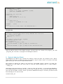
Con t r ol Ar du in o Re se t
The Raspberry- Pi GPI O 8 pin cont rols t he Arduino reset pin when t he j um pers are in place.
When st art ing t he pin is LOW and t hus t he Arduino chip is held in reset . To cont rol t he reset
( gpio- 8 pin) you can use t he script s shown below.
Don’t forget t o change t he m ode of t he t ext file t o execut able form at : (chm od 777 reset _off).
Depending on your pat h you m ay have t o call t he script st art ing wit h a < dot > < slash> :
“ ./ reset _off” .
Alt ernat ive copy t he script s t o / usr/ bin: “ sudo cp reset _off / usr/ bin” . I f you want t he Raspberry
Pi t o always execut e t he script at boot up you have t o edit t he / et c/ rc.local file. Make sure t hat
you have t he full pat h in t here. Thus if you have inst alled t he script in / usr/ bin you have t o add
t he following line t o / et c/ rc.local:
/ usr/ bin/ reset _off
25 | P a g e
r e se t_ off
The following script will release t he Arduino reset and t hus m ake t hat t he Arduino chip runs. I t
only works if t he Gert Duino is plugged in t o t he Raspberry Pi and t he reset j um per is in place.
#!/usr/bin/sudo bash
# Set GPIO pin 8, high releasing Arduino reset
sudo echo "8"
>/sys/class/gpio/export
sudo echo "out" >/sys/class/gpio/gpio8/direction
sudo echo "1"
>/sys/class/gpio/gpio8/value
sudo echo "8"
>/sys/class/gpio/unexport
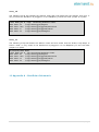
r e se t_ on
The following script will assert t he Arduino reset and t hus m ake t hat t he Arduino chip st ops, is
held in reset . I t only works if t he Gert Duino is plugged in t o t he Raspberry Pi and t he reset
j um per is in place.
#!/usr/bin/sudo bash
# Set GPIO pin 8, low activating Arduino reset
sudo echo "8"
>/sys/class/gpio/export
sudo echo "out" >/sys/class/gpio/gpio8/direction
sudo echo "0"
>/sys/class/gpio/gpio8/value
sudo echo "8"
>/sys/class/gpio/unexport
1 0 Appe n dix A : Ge r t D u in o Sch e m a t ic
26 | P a g e