1
ExtraNET CC,
ExtraNET Avalanche,
ExtraNET µCC
and
User Manual and Integrator Documentation
© 2006-2008 Crystalline Technology, Inc.
REVISION TRACKING SHEET
THIS MANUAL MAY BE REVISED PERIODICALLY TO INCORPORATE NEW OR UPDATED
INFORMATION. THE DATE REVISION LEVEL OF EACH PAGE IS INDICATED AT THE
BOTTOM OF THE PAGE ALONG WITH THE PAGE NUMBER. A MAJOR CHANGE IN THE
CONTENT OF THE MANUAL ALSO CHANGES THE DATE OF THE MANUAL, THAT
APPEARS ON THE FRONT COVER. LISTED BELOW IS THE DATE REVISION LEVEL OF
EACH PAGE.
PAGE REVISION
DATE
DESCRIPTION
All
All
All
All
1/12/06
10/31/06
11/20/06
02/17/08
Preliminary Documentation
Initial Public Release
Added safety warnings for Div 2 application
Added sections for Avalanche and µCC
Preliminary
Rev 0.1
Rev 0.2
Rev 0.3
© CRYSTALLINE TECHNOLOGY INC. 2003-2008. ALL RIGHTS RESERVED.
EXTRANET CC, EXTRANET AVALANCHE, AND EXTRANET µCC ARE A TRADEMARKS OF
CRYSTALLINE TECHNOLOGY, INC. ALL OTHER MARKS ARE THE PROPERTY OF
THEIR RESPECTIVE OWNERS.
PRINTED IN THE U.S.A.
WHILE INFORMATION IS PRESENTED IN GOOD FAITH AND BELIEVED TO BE
ACCURATE, CRYSTALLINE TECHNOLOGY DOES NOT GUARANTEE SATISFACTORY
RESULTS FROM RELIANCE ON SUCH INFORMATION. NOTHING CONTAINED HEREIN IS
TO BE CONSTRUED AS A WARRANTY OR GUARANTEE, EXPRESS OR IMPLIED,
REGARDING THE PERFORMANCE, MERCHANTABILITY, FITNESS OR ANY OTHER
MATTER WITH RESPECT TO THE PRODUCTS, NOR AS A RECOMMENDATION TO USE
ANY PRODUCT OR PROCESS IN CONFLICT WITH ANY PATENT. CRYSTALLINE
TECHNOLOGY, INC. RESERVES THE RIGHT, WITHOUT NOTICE, TO ALTER OR
IMPROVE THE DESIGNS OR SPECIFICATIONS OF THE PRODUCTS DESCRIBED HEREIN.
1
TABLE OF CONTENTS
INTRODUCTION .................................................................................................................................. 4
RECITALS ............................................................................................................................................. 4
1. DEFINITIONS ........................................................................................................4
2. GRANT OF LICENSE ............................................................................................4
3. TERMINATION .....................................................................................................5
4. COPYRIGHT ..........................................................................................................5
5. APPLICABLE LAW ...............................................................................................5
6. WARRANTIES AND LIMITATION ON LIABILITY ...........................................5
6.1 ONE-YEAR LIMITED WARRANTY...............................................................5
This is Crystalline Technology, Inc.'s exclusive written warranty.............................6
QUICK START...................................................................................................................................... 7
INTRODUCTION TO THE EXTRANET............................................................................................. 9
Features.......................................................................................................................9
Overview...................................................................................................................10
CONNECTION TO EXTERNAL EQUIPMENT................................................................................ 11
DIAGNOSTIC CABLE ........................................................................................................................ 14
CONFIGURATION ............................................................................................................................. 15
Configuration Menu ..................................................................................................15
D) Display Settings....................................................................................................15
L) List Event Log ......................................................................................................16
C) Connect to Globalstar gateway..............................................................................16
H) Hangup Globalstar Modem...................................................................................16
B) Reset ExtraNET CC..............................................................................................17
G) Configure Globalstar Modem ...............................................................................17
R) Show Communication Status ................................................................................17
S) Test BSAP Connection..........................................................................................17
T) Test ROC Connection ...........................................................................................18
F) Configure ExtraNET CC Mode .............................................................................18
G) Configure Globalstar Modem ...............................................................................20
W) Configure Wireless Modem .................................................................................21
R) Show Communication Status ................................................................................22
USING EXTRANET CC FOR SCADA APPLICATIONS.................................................................. 23
Modbus/IP.................................................................................................................25
VB.NET SAMPLE PROGRAM........................................................................................................... 26
EXTRANET AVALANCHE ................................................................................................................ 27
Overview:..................................................................................................................27
Features:....................................................................................................................27
Theory of Operation ..................................................................................................28
GETTING READY TO USE AVALANCHE ...................................................................................... 30
2
Installation Considerations.........................................................................................30
Interfacing RTU ........................................................................................................30
AVALANCHE MENU AND CONFIGURATION .............................................................................. 32
Email Attachment Formats ........................................................................................38
Binary File - FloBoss.............................................................................................38
Comma Delimited File Format – FloBoss ..............................................................43
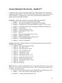
COMMA DELIMITED FILE FORMAT – REALFLO™ .................................................................. 47
SMS MESSAGES ................................................................................................................................. 50
EXTRANET µCC OVERVIEW .......................................................................................................... 53
ExtraNET µCC Configuration ...................................................................................55
Obtaining Control of ExtraNET µCC.........................................................................56
Installation of ExtraNET µCC ...................................................................................56
Integrating ExtraNET µCC into an application ..........................................................57
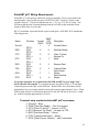
ExtraNET µCC Wiring Requirements........................................................................58
APPENDIX A – UL CERTIFICATION .............................................................................................. 60
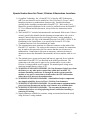
Special Instructions for Class I, Division 2 Hazardous Locations...............................61
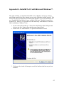
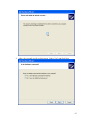
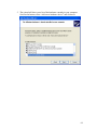
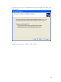
APPENDIX B - EXTRANET UCC WITH MICROSOFT WINDOWS™.......................................... 62
SPECIFICATIONS: ............................................................................................................................. 76
CONTACT INFORMATION .............................................................................................................. 77
3
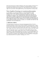
Introduction
ExtraNET comes in three different configurations. ExtraNET CC is a complete solution
functioning as a “remote terminal server”. The ExtraNET CC contains a TCP/IP and
UDP/IP stack and supports a static IP address. ExtraNET CC can also be used to
originate a TCP session with a predefined host.
ExtraNET Avalanche is a “store and forward” device that acquires data from the
customer’s RTU and at predetermined times, sends this data as an email.
ExtraNET µCC is a legacy product that functions as a dial up modem would. Crystalline
Technology has added to the basic functionality of the Globalstar 1620 / 1720 modems
by including a processor that restores user configurations in the event of a power loss or
reset.
This manual contains information on all three of the products.
Recitals
Use of Crystalline Technology, Inc. (“CTI”) products requires three elements: the
SOFTWARE, the hardware, and a personal computer or RTU. The SOFTWARE is
protected by copyright laws and international copyright treaties, as well as other
intellectual property laws and treaties. The SOFTWARE is not sold, and instead is only
licensed for use, strictly in accordance with this document. The hardware is protected by
various patents, and is sold, but this agreement does not cover that sale, since it may not
necessarily be sold as a package with the SOFTWARE. This agreement sets forth the
terms and conditions of the SOFTWARE LICENSE only.
1. DEFINITIONS
1.1 Customer. Customer means the entity or individual that downloads the SOFTWARE.
2. GRANT OF LICENSE
2.1 Rights and Limitations of Grant. Crystalline Technology, Inc. (“CTI”) hereby grants
Customer the following non-exclusive, non-transferable right to use the SOFTWARE,
with the following limitations:
2.1.1 Rights. Customer may install and use one copy of the SOFTWARE on a single
computer, and except for making one back-up copy of the Software, may not otherwise
copy the SOFTWARE. This LICENSE of SOFTWARE may not be shared or used
concurrently on different computers.
No Reverse Engineering. Customer may not reverse engineer, decompile, or disassemble
the SOFTWARE, nor attempt in any other manner to obtain the source code.
No Separation of Components. The SOFTWARE is licensed as a single product. Its
component parts may not be separated for use on more than one computer, nor otherwise
used separately from the other parts.
4
No Rental. Customer may not rent or lease the SOFTWARE to someone else.
3. TERMINATION
This LICENSE will automatically terminate if Customer fails to comply with any of the
terms and conditions hereof. In such event, Customer must destroy all copies of the
SOFTWARE and all of its component parts
4. COPYRIGHT
All title and copyrights in and to the SOFTWARE (including but not limited to all
images, photographs, animations, video, audio, music, text, and other information
incorporated into the SOFTWARE), the accompanying printed materials, and any copies
of the SOFTWARE, are owned by Crystalline Technology, Inc.(“CTI”), or its suppliers.
The SOFTWARE is protected by copyright laws and international treaty provisions.
Accordingly, Customer is required to treat the SOFTWARE like any other copyrighted
material, except as otherwise allowed pursuant to this LICENSE and that it may make
one copy of the SOFTWARE solely for backup or archive purposes.
5. APPLICABLE LAW
This agreement shall be deemed to have been made in, and shall be construed pursuant
to, the laws of the State of Nevada and / or the United States of America.
6. WARRANTIES AND LIMITATION ON LIABILITY
6.1 ONE-YEAR LIMITED WARRANTY
Crystalline Technology, Inc. ExtraNET CC is warranted to be free of defects in material
and workmanship for one year from date of installation.
Crystalline Technology, Inc. will, at its election, repair, replace or make appropriate
adjustment where Crystalline Technology, Inc. inspection discloses any such defects
occurring in normal usage within one (1) year after installation. Crystalline Technology,
Inc. is not responsible for removal or installation costs.
To obtain warranty service contact Crystalline Technology, Inc. either through your
Dealer or by writing Crystalline Technology, Inc., Attn: Customer Service Department,
PO Box 8423, Pueblo, CO, USA, or by calling 1-888-737-9817 from within the USA or
Canada and 001-719-543-2577 from within Mexico.
IMPLIED WARRANTIES INCLUDING THAT OF MERCHANTABILITY AND
FITNESS FOR A PARTICULAR PURPOSE ARE EXPRESSLY LIMITED IN
DURATION TO THE DURATION OF THIS WARRANTY. CRYSTALLINE
TECHNOLOGY, INC. AND/OR SELLER DISCLAIMS ANY LIABILITY FOR
SPECIAL, INCIDENTAL OR CONSEQUENTIAL DAMAGES.
5
Some states/provinces do not allow limitations on how long an implied warranty lasts, or
the exclusion or limitation of special, incidental or consequential damages, so these
limitations and exclusions may not apply to you. This warranty gives you specific legal
rights. You may also have other rights which vary from state/province to state/province.
This is Crystalline Technology, Inc.'s exclusive written warranty.
6.2 No Liability for Consequential Damages. TO THE MAXIMUM EXTENT
PERMITTED BY APPLICABLE LAW, IN NO EVENT SHALL Crystalline
Technology, Inc.(“CTI”), OR ITS SUPPLIERS BE LIABLE FOR ANY SPECIAL,
INCIDENTAL, INDIRECT, OR CONSEQUENTIAL DAMAGES WHATSOEVER
(INCLUDING, WITHOUT LIMITATION, DAMAGES FOR LOSS OF BUSINESS
PROFITS, BUSINESS INTERRUPTION, LOSS OF BUSINESS INFORMATION, OR
ANY OTHER PECUNIARY LOSS) ARISING OUT OF THE USE OF OR INABILITY
TO USE THE SOFTWARE, EVEN IF Crystalline, Inc. HAS BEEN ADVISED OF THE
POSSIBILITY OF SUCH DAMAGES.
7. MISCELLANEOUS
The United Nations Convention on Contracts for the International Sale of Goods is
specifically disclaimed. If any provision of this LICENSE is inconsistent with, or cannot
be fully enforced under, the law, such provision will be construed as limited to the extent
necessary to be consistent with and fully enforceable under the law. This agreement is the
final, complete and exclusive agreement between the parties relating to the subject matter
hereof, and supersedes all prior or contemporaneous understandings and agreements
relating to such subject matter, whether oral or written. Customer agrees that it will not
ship, transfer or export the SOFTWARE into any country, or use the SOFTWARE in any
manner, prohibited by the United States Bureau of Export Administration or any export
laws, restrictions or regulations. This LICENSE may only be modified in writing signed
by an authorized officer of Crystalline Technology, Inc. (“CTI”).
6
Quick Start
7
Each ExtraNET CC satellite communication system is provided in housing designed to
meet the NEMA Type 4x specifications and to operate in a Class I, Division 2, Groups C
& D environment with a nonincendive rating (see Appendix A).
1) Locate a suitable site for mounting the ExtraNET CC. Brackets are provided to
allow easy mounting to a pipe using user supplied u-bolts.
2) Configure the Gas Flow Computer using Group 2, Local 1, and 9600 baud as the
communication settings for communications used with the ExtraNET CC.
3) A three wire interface is required to the gas flow computer. It is suggested that
you use the 5 pin Phoenix connector for field wiring to the gas flow computer.
J1 Pin 1 to Gas Flow Computer RS232 Transmit
J1 Pin 3 to Gas Flow Computer RS232 Receive
J1 Pin 5 to Gas Flow Computer RS232 Ground
4) Connect power to the 2 Pin Phoenix connector at J5. The voltage should be
between 12 and 15 volts with positive on Pin 1 (closest to 10 pin connector) and
ground to Pin 2 (closest to edge of board).
5) Connect the diagnostic cable to the 10 pin Phoenix connector J4, the other end to
a com port on your computer. Using HyperTerminal set to 9600 baud, 8 bits, 1
stop, no parity you should see a menu when you press the space bar.
6) For a Fisher ROC installation you can press the “T” command. You should see a
message indicating successful communication to the GFC you are connected to.
7) All other settings will be preconfigured at the factory to minimize installation
issues.
8
Introduction to the ExtraNET
Features
ExtraNET CC delivers seamless point to point data communications over a transparent
network using satellite and / or a GSM/GPRS, 1X, or CDMA “cellular” modem.
ExtraNET CC delivers reliable digital data virtually anywhere in the world using
QUALCOMM’s patented CDMA technology and the Globalstar constellation of LowEarth-Orbit (LEO) satellites. Also supported is an optional GPS for position and
velocity data.
ExtraNET CC takes care of the IP network requirements and provides a transparent
RS232 or RS485 interface to your equipment. It works with almost any host that
supports TCP or UDP over an IP network giving you the complete comfort of managing
your own data.
Each ExtraNET CC satellite communication system is provided in housing designed to meet the NEMA
Type 4x specifications and to operate in a Class I, Division 2, Groups C & D environment with a
nonincendive rating (see Appendix A).
ExtraNET CC Features:
• Approved NEMA 4X fiberglass enclosure provides weather protection in most
environments.
• Optional Static IP
o Allows complete integrated connectivity via a private virtual network (VPN)
direct from your host server to the Globalstar Network Operations Center (NOC).
Simply send a TCP or UDP packet to a private IP and ExtraNET will establish the
connection in approximately 6 seconds. Data can then be sent or received from
the remote site with a throughput of 9.6 kbps full duplex.
o Alternatively the remote device can initiate a connection with your host.
o Secure access via the Internet can be arranged through a public gateway where a
VPN is not desirable or possible (roaming host)
• Default Dynamic IP allows the remote user to access the public internet for host-less
applications.
o SMS messages can be sent to the ExtraNET CC to initiate remote action and or
connections back from a Dynamic IP.
• Five configurable I/O points user configured for analog input (0 to 5 VDC) or digital
output for remote monitoring and control in standalone applications.
• Optional cellular modems are available for most carriers.
• Optional GPS module supports NMEA 188, TIAP, and TSIA protocols
• Optional local data storage up to 1 GB using removable SD memory
• Activity timers automatically disconnect on user configured “no activity” or
“maximum connect time” parameters.
• Always On, always ready operation. Custom low power modes available on request.
9
Overview
ExtraNET CC is a universal communication controller supporting the Globalstar™ data
modem to allow efficient data communications from virtually anywhere in the world. In
addition to satellite support, ExtraNET CC also supports optional modules for
GSM/GPRS™, CDMA™, Edge™, and 1 x™ cellular network providing a very flexible
platform capable of utilizing existing infrastructure.
ExtraNET CC works with the #777 data service offered by Globalstar and takes care of
the PPP negotiations and provides a complete TCP/IP stack. External equipment can be
connected to the ExtraNET CC through the RS232/RS485 software selectable interface
and communicate at any standard baud rate from 300 to 115,200 baud using a standard 8
bit asynchronous protocol.
ExtraNET CC supports both the Dynamic IP and the Static IP modes of Globalstar. In a
Dynamic IP mode, ExtraNET CC will respond to SMS commands and is capable of
gathering data from customer equipment and establishing a connection on demand. In
the Static IP mode, ExtraNET CC will in addition to the SMS mode, support data on
demand by establishing a connection to your host upon reception of any IP traffic.
Other features of ExtraNET CC include optional GPS for location, movement, and/or
time specific functions. Five I/O points are provided which can be selectivity configured
for analog input (10 bit 0 to 5 volts DC) or digital output capable of sourcing 25 mA of
power. An additional output is provided which will switch the source 12VDC and
provide up to 1 Amp of power for powering external sensors or equipment.
An SD (Secure Digital) socket is provided for data logging applications. SD memory
devices with up to 1GB of storage capacity are commonly available and most electronic
specialty stores where digital cameras and PDA’s are sold.
ExtraNET CC is packaged in a NEMA 4X fiberglass
enclosure, resistant to moisture, dust, and corrosion to
provide many years of trouble free service.
The result is a very efficient communication solution that
works with virtually any host to provide access to remote
equipment with out the traditional requirements for
infrastructure (towers). Economical airtime packages are
available to suit virtually any application.
10
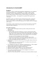
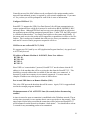
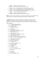
Connection to External Equipment
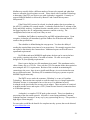
ExtraNET supports several interfaces to optional or customer supplied equipment. J4
(top left) is a 10 pin Phoenix™ connector that allows connection to external sensors and
controls. The connector is labeled from left to right (1 to 10) and arranged in pairs. Pins
1 & 2 are for IO 1 with pin 1 being signal and pin 2 being ground. Pins 2 & 3 are for IO
2 and so forth to pins 9 & 10 for IO 5 (notice that future versions of ExtraNET will
change the definition of pin 2)
Each of the IO points are supported in custom versions of ExtraNET CC and can be
defined as analog input or digital output. When configured as an output each point can
sink or source up to 25mA at 5 VDC. A 10 bit analog to digital converter is used when
configured for analog input. Each IO point is protected against surges and spikes.
J5 (top right) is the power input to the board. A clean power source capable of providing
6 to 16VDC at up to 5.5 Watts of power (for transmit) is required.
Figure 1 (ExtraNET Diagram)
11
The Program interface is used for configuration and special diagnostics. A lap top
computer or other ASCII terminal can be connected to this port. Please see the section on
“Diagnostic Cable” for more information about the required cable and interface for this
port.
U7 is for an optional CDMA, GSM/GPRS, Edge, 1X, Bluetooth, or Ethernet module
installed in the three vertical connectors located below J4 and J5. Please contact
Crystalline Technology, Inc. for more information concerning these modules.
U8 supports an optional high performance 12 Channel GPS that can be used for
positional or time critical applications. When the GPS is used then the battery B1 socket
should have a lithium CR2025 3 Volt battery installed to reduce GPS startup time.
F1 is a 2Amp slow blow fuse provided to protect the ExtraNET CC from excessive
power.
U9 is for applications where large amounts of data need to be retained. A standard SD
(Secure Digital) is used with capacities up to 1GB. As an example, in natural gas
applications a sample of DP, line pressure, temperature, and flow rate could be logged
once per second for over 2 years. Other applications for logging GPS data, audit data, or
other special events can be conceived. Please contact Crystalline Technology, Inc. to
discuss any application of the SD memory that you might desire.
J1 (center left) is a 5 pin Phoenix™ connector for interfacing to customer supplied
equipment. This interface is user selectable during configuration for RS232 or RS485
levels. When configured for RS485 a full duplex 4 wire interface is supported. The
ExtraNET CC has a 100 ohm termination resistor on the receive lines.
For 2 wire half duplex RS422 / RS423:
Select the RS485 option in the setup. Use the 5 pint connector at J1 and install a
jumper between Pins 1 and 3 and used this as A+ pin. Place a jumper between
pins 2 and 4 and use this as the B- pin in wiring a 2 wire RS-422 connection.
For 4 wire full duplex RS485:
Use the connector at J1. Pins 1 and 2 is the receive data (data sent to the
ExtraNET CC) Pins 3 and 4 are transmit data (data sent from the ExtraNET CC)
Pin 5 is ground
For RS232:
Pin 1 is receive data (data sent to the ExtraNET CC)
Pin 3 is transmit data (data sent from the ExtraNET CC)
Pin 5 is ground
(Pins 2 and 4 are not supported when configured as RS232)
J2 (top left) is designed to support the Globalstar 1620 modem. This cable is normally
included as part of an ExtraNET CC package.
12
(J2 Interface Cable to Globalstar 1620 modem)
DB-9 M
DB-25F
Description
ExtraNET CC 1620 Modem
Pin
Pin
Pin
Pin
Pin
Pin
Pin
Pin
2
3
4
5
6
7
8
9
Pin
Pin
Pin
Pin
Pin
Pin
Pin
Pin
2
TX Data
3
RX Data
4 & Pin 20 DTR
7
Ground
6
DSR
5
CTS
9 & Pin 10 +12 VDC Power
8
DCD
J3 (bottom left) is shared with J1 and is the RS232 interface to customer equipment. The
function of J3 is shared with the 5 pin Phoenix connector labeled J1 (middle left). Please
reference the table below for pin definitions of the DB9F J3 connector. This connector
does not strictly conform to RS-232 standards and caution is recommended to avoid
damage to the ExtraNET CC. This connector shares function with J1 and is only valid
when ExtraNET CC is configured for RS-232. When RS-485 is selected you should use
J1 and leave J3 disconnected:
(J3 Interface - RS232 Customer Interface)
Pin 1
Pin 2
Pin 3
Pin 4
Pin 5
Pin 6
Pin 7
Pin 8
Pin 9
DCD Output (0 to 5 Volts)
TX Data (RS-232)
RX Data (RS-232)
DTR Output (0 to 5 Volts)
Ground
DSR Output (0 to 5 Volts)
RTS Output (RS-232)
CTS Input (RS-232)
+8 Volts (Very Low Power)
13
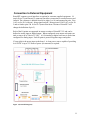
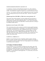
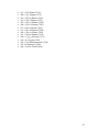
Diagnostic Cable
After completing the mounting and wiring of the ExtraNET CC installation you should
connect to the unit with a lap-top computer or other suitable terminal to complete the
configuration. Diagnostics are supported by connecting a terminal or computer to the 10
pin I/O connector of the ExtraNET CC. The I/O is restricted to signal levels of 0 to 5
VDC and do not strictly conform to RS232 standards when using the 10 pin I/O
connector. A cable is provided that will handle the interface requirements with a DTE
device such as a lap top computer running the HyperTerminal program.
It is very important that you use this special cable with the approved interface since the
diagnostic port on the ExtraNET CC is not RS232 and is not protected from improper
use. Permanent and un-repairable damage will result if proper cables are not used.
Figure 2 (diagnostic cable)
You are now ready to perform the final steps of the installation. Using HyperTerminal or
some other suitable terminal emulation program select the following settings:
Baud Rate:
Data Bits:
Stop Bits:
Parity:
Handshake:
9600
8
2
None
None
14
Configuration
Upon connection to the ExtraNET CC you may enter a space (single press of the space
bar) and a menu of commands will be presented. Only after completely understanding
the commands should you attempt to make any changes in the configuration of the
ExtraNET CC. It is quite easy to end up with a device that doesn’t work simply because
the configuration is incorrect for the application required. The following menu is
representative. The menu will actually provide different options depending on the
configuration that it is currently using. Using this interface you can change the way that
the unit works.
NOTICE: The Globalstar 1620 data modem can be configured for baud rates ranging
from 9600 baud to 115200 baud. Since the over the air rate is 9600 baud there are some
considerations that are made for buffering data. As an example, when ever possible the
1620 should be configured for the same data rate as the customer equipment connected
to J1 or J3. Although the I/O of the ExtraNET CC is interrupt driven with buffers for
data, there are opportunities where possible data overruns could occur if you are trying
to send more data than can be buffered.
Configuration Menu
ExtraNET CC
(c) 2005,2006 by Crystalline Technology, Inc
See http://www.ExtraNETCC.com for more information.
Compiled 05-Jan-06 08:57:44 Serial# 000003f4
D) Display Settings
C) Connect to Globalstar gateway
H) Hangup Globalstar Modem
M) Configure SMTP
E) Send E-Mail
B) Reset ExtraNET CC
F) Configure ExtraNET CC Mode
G) Configure Globalstar Modem
W) Configure Wireless Modem
R) Show Communication Status
Each of these commands are simple 1 character commands. These commands should be
used when no sessions to the Globalstar or optional modems are in progress.
D) Display Settings
The display settings command will show a synopsis of the various settings in the
ExtraNET CC. It is a good idea to issue the “D” command after going through the
15
configuration of the “F” command. The “D” will display several different items. Below
is an example of the information displayed in the “D” command.
Not connected
Configured for FixedIP Service
UDP receive port 2101 open
UDP send to port 2101 at 10.202.0.35
Will check for SMS messages
Will hangup on TCP close
No activity timeout: 5
Maximum Connect Time: 300
Terminal baud rate: 9600
Terminal port configured for RS232
socket 0: port=0, State=TCP_CLOSED
socket 1: port=0, State=TCP_CLOSED
socket 2: port=0, State=TCP_CLOSED
L) List Event Log
The ExtraNET CC is capable of logging the previous 100 connectivity and initialization
events. This is a very useful feature particularly if you need to know when there is
satellite coverage available. The event log will tell you when coverage became available
and how long your unit was in a coverage area. All times listed in the event log are UTC.
The correct time will be acquired from the satellite or cellular system. Any event with a
date and time of 0/00/00 0:00:00 indicates that the correct time was not acquired when
that even was logged. The even log can be cleared by selecting the “Clear event log?”
option in the “Configure ExtraNET CC Mode” (“F”) command.
C) Connect to Globalstar gateway
The “C” command is used to initiate a PPP session with the Globalstar #777 internet
service. This command is primarily used in testing before we ship the product to ensure
that the modem is activated and that the antenna and cabling function properly. Keep in
mind that issuing the “C” command does use airtime on the satellite network as it fully
establishes 2 way communication between ExtraNET CC and the Globalstar network.
There may be circumstances in which the end user may want to use the “C” command,
but it is generally used for testing and diagnostic purposes.
H) Hangup Globalstar Modem
The “H” command is used to force the modem to disconnect if a connection is active and
go through a complete reset. This is also a command which is primarily used for testing
and diagnostic purposes. The end user will rarely need to use this command.
16
B) Reset ExtraNET CC
The “B” command is used to perform a graceful reset of the ExtraNET CC. This
command will gracefully disconnect the 1620 from the Globalstar network and cause the
ExtraNET CC board to re-initialize the 1620. This will also ensure that all user selectable
parameters are loaded properly. It is strongly recommended to issue the “B” command
after changing any configuration in the “F” command.
G) Configure Globalstar Modem
The “G” command is used to open a terminal connection to the Globalstar modem. This
allows the user to issue AT commands to the Globalstar 1620 modem. This command is
also used primarily for testing, but can also be very beneficial to the end user. The “G”
command simply opens a terminal that allows you to issue any compatible AT command
to the modem for a multitude of different functions. NOTE: While in the Globalstar 1620
Terminal the ExtraNET CC is unable to accept any incoming connections. It is important
to note that the terminal will automatically close after 120 seconds to prevent the
ExtraNET CC from being locked into an unusable state for remote terminated data
applications.
R) Show Communication Status
The “R” command is capable of displaying several different types of information. When
issued, you will see the status of the Globalstar modem. If there is no 1620 attached to
the ExtraNET CC you will simply see “Globalstar not ready.” If a 1620 is connected and
there is coverage available, you will see “Globalstar online.” If your unit is configured to
use cellular, you will see its status here as well. When the “R” command is issued,
ExtraNET CC also sends “at$qcstatus” to the 1620 and returns the result to you. This is a
very fast way to determine if you currently have satellite coverage. It also saves you
from having to enter the Globalstar terminal to manually input the command.
S) Test BSAP Connection
This command is only used in S.C.A.D.A. (supervisory control and data acquisition)
applications. The “S” command will test communication between the ExtraNET CC and
a Bristol BabcockTM flow computer. It is advisable to issue this command after initial
installation if your configuration uses the BSAPTM protocol. This will ensure that
communication is taking place between your equipment and the ExtraNET CC.
17
T) Test ROC Connection
This command is also used only in S.C.A.D.A. applications. The “S” command will test
communication between the ExtraNET CC and a FisherTM flow computer. It is advisable
to issue this command after initial installation if your configuration uses the ROCTM
protocol. This will ensure that communication is taking place between your equipment
and the ExtraNET CC.
F) Configure ExtraNET CC Mode
Upon entry you will be presented with a series of questions. Some of the questions will
include the current setting that is in effect for that question.
Fixed IP Service? (Y)
Are you using the Static IP mode offered by Globalstar? The Static IP mode requires a
VPN connection to the Globalstar NOC (Network Operations Center) and modems that
have been specially provisioned for service with a Static IP. ExtraNET CC will answer
inbound requests to establish a data session with the network if you answer Y for yes. If
you answer N then the ExtraNET CC will check for SMS messages about once per
second and respond appropriately as required.
Check for SMS messages? (N)
Even configured as a Static IP node there are opportunities where the SMS message still
has value. As an example, if you are located deep in a canyon that has limited view of
the sky; you may not have continuous coverage by the Low Earth Orbiting (LEO)
satellites operated by Globalstar. In these cases a host may wish to send a SMS message
to a remote note. Globalstar will queue this SMS message until it gets the destined node
registered on the satellite. Thus as soon as a satellite goes over head (typically in only a
few minutes) the ExtraNET CC will receive the SMS message and initiate the connection
back to the host. This will reduce possible errors on the host induced by polling a remote
unit that is not within satellite coverage at that time.
Configure as Internet/Intranet switch? (N)
In some applications ExtraNET CC can be used to provide Internet or Intranet service
based upon the availability of a signal from a cellular site using an optional GSM/GPRS
or CDMA interface. Since connection through these services is typically lower cost than
through the satellite ExtraNET CC will use them where possible. If the service drops out
or is not available then ExtraNET CC will automatically switch to the Globalstar network
thus providing service virtually anywhere in a mobile environment.
MAC address 0x00-0x00-0x00-0x00-0x00-0x02
Change? (N)
18
Generally not used, the MAC address can be configured with a unique number on the
network when enhanced security is required by your network administrator. If you enter
a Y for yes then you will be prompted for each of the 6 octets of information.
Configure UDP Port? (Y)
ExtraNET CC supports the UDP (User Data Protocol) for efficient communication to
remote equipment where a high level protocol is used such as BSAP, MODBUS, ROC,
and many others. Although UDP does not have any error checking built in with retries,
the application protocol being transported generally does. Unlike TCP, the UDP protocol
is considered connectionless. You simply send a packet to the remote node blindly. If
the remote node receives the packet and is supposed to respond then it will do so in a like
fashion. This is analogous to standard data radio service where you transmit to a remote
node and if it receives and is program to respond it will do so.
UDP Port to use on ExtraNET CC (2101)
We suggest port 2101 used by our API (Application Program Interface). Any port from 1
to 65535 may be used.
IP Address of Remote Machine is 10.202.0.35, Enter New Address:
BYTE0: 10
BYTE1: 202
BYTE2: 0
BYTE3: 35
Since UDP is a “connectionless” protocol, ExtraNET CC needs to know what the IP
address is of the machine that will be receiving the data from the ExtraNET CC. This
should be a network address that is available to the unit when ever connected. A
dynamic IP on the host computer is not currently supported. You must enter the
complete IP address one octet (byte) at a time as shown above.
Port to send UDP data to on Remote Machine (2101)
This is the UDP port on the host that data will be sent to. Again, 2101 is suggested and
used in the example programs included.
Maximum amount of NO ACTIVITY time (10 seconds) before disconnecting
satellite?
A timer is started as soon as connection is established to the Globalstar network. The no
activity timer (seconds) is reset anytime data is sent or received over the network. If the
timer expires before being reset then the connection will be broken and ExtraNET CC
will disconnect from the network to eliminate “dead airtime”. You should allow at least
2 seconds for any outstanding packet to be transmitted.
19
Absolute maximum time allowed for connection? (15)
A second timer is started in a similar fashion but cannot be reset. If the connection
exceeds this time (measured in seconds) then ExtraNET CC will disconnect from the
satellite. You should allow enough time to perform any communications that you might
want to do. You want this to disconnect only if something has gone terribly wrong and a
unit is just sending data non stop or has some other failure. This time is measured in
seconds.
Minimum signal from GSM/GPRS or CDMA before selecting Satellite (-95)?
This question really only has meaning if you have configured the unit for Internet or
Intranet service above. The number represents a RSI (received signal indicator) and
although negative should be entered without the minus “-“ sign. The lower the number,
the stronger the signal required by the GSM/GPRS or CDMA modem before switching to
the Globalstar satellite network.
Baud Rate for local Terminal / RTU (19200)?
This is the baud rate that is used to communicate with the customer supplied equipment
(or a computer if using the Internet / Intranet mode). Any standard baud rate from 300 to
115200 baud can be used but if you want 115200 baud you must enter 11520 and leave
off the last zero. This is due to the way ExtraNET CC stores the number in a 16 bit
register that only goes to 65535. Standard baud rates supported are: 300, 600, 1200,
2400, 4800, 9600, 19200, 38400, 57600, and 115200 baud. This is the baud rate used to
communicate with the customer equipment, not the actual baud rate used over the
satellite or the cellular system.
Use RS232 (Y) or RS485 (N)? (Y)
Finally you can select the levels used to communicate with the customer equipment.
RS232 is available on the DB9 connector while both RS232 and RS485 are available on
the 5 pin phoenix connector provided. Refer to the wiring diagrams for more information
on connecting customer equipment.
G) Configure Globalstar Modem
Provided for direct access to the Globalstar 1620 data port on the modem. Any of the
recognized “AT” commands may be executed. While in this mode ExtraNET CC will
not recognize any normal data connects to the Globalstar gateway and will not negotiate
the PPP session. It is important that you properly exit this mode or you will render the
ExtraNET CC non-functional for normal applications. To exit this mode you must enter
“QUIT” all in upper case.
20
This function is sometimes useful to determine what gateway you are currently registered
with on the Globalstar network. As an example you can enter the AT$QCSTATUS as
shown below:
GlobalStar 1620 Terminal ('QUIT' to exit)
at$qcstatus
SERVICE AVAILABLE: YES
SERVICE MODE: GLOBALSTAR
PROVIDER: GSTAR USA
GATEWAY: 1
RSSI: 4
REGISTRATION: YES
ROAMING: NO
CALL STATE: IDLE
CALL TYPE:
CALL DURATION: 0
NUMBER:
OK
In this example we have service available and are registered on the satellite using
gateway 1 with a RSSI of 4 (out of 4). This information is useful in determining
availability of service. You should always try to get the best possible view of the sky
when determining the mounting location of the ExtraNET CC. Since the Globalstar
network consists of a number of low-earth-orbiting (LEO) satellite it is likely that if you
wait a few minutes a satellite will pass over head somewhere in the open sky that you can
see.
Again, it is important that you properly exit from this option so ExtraNET CC can resume
its normal mode of operation. When you enter the “QUIT” (case sensitive) you will see
the menu reappear upon exit. You will not see the “QUIT” echoed back to your terminal.
W) Configure Wireless Modem
This option is not available on units not equipped with the wireless modem. If you have
an optional modem plugged into the socket at U7 then you may send commands to the
modem in the same fashion as was used for the Globalstar modem above. The same rules
apply, you MUST exit the W option with the “QUIT” all in upper case.
Each version of the socket modem has a unique set of commands that are supported.
Normally the socket modem will be preconfigured to meet your application requirements
and this mode is not needed for any other configuration of the modem.
21
R) Show Communication Status
The “R” command is capable of displaying several different types of information. When
issued, you will see the status of the Globalstar modem. If there is no 1620 attached to
the ExtraNET CC you will simply see “Globalstar not ready.” If a 1620 is connected and
there is coverage available, you will see “Globalstar online.” If your unit is configured to
use cellular, you will see its status here as well. When the “R” command is issued,
ExtraNET CC also sends “AT$QCSTATUS” to the 1620 and returns the result to you.
This is a very fast way to determine if you currently have satellite coverage. It also saves
you from having to enter the Globalstar terminal to manually input the command.
SERVICE AVAILABLE: YES
SERVICE MODE: GLOBALSTAR
PROVIDER: GSTAR USA
GATEWAY: 1
RSSI: 3
REGISTRATION: YES
ROAMING: NO
CALL STATE: IDLE
CALL TYPE:
CALL DURATION: 18
NUMBER: #777
OK
Globalstar Online
In the example above, the unit has service available, is operating in the Globalstar service
mode and has service provided by GSTAR USA. Service is currently being provided
from Gateway 1 (Clifton, TX) and has a receive signal strength indicator (RSSI) of 3
(scaled from a poor signal of 0 to a very good signal at 4). The unit is currently
registered and not roaming. The Call Duration is the total length of the last data session.
For ExtraNET all connects are made through the #777 data services and enjoy the special
airtime rates offered by Globalstar.
22
Using ExtraNET CC for SCADA Applications
In order to contain costs, ExtraNET CC is only connected to the Globalstar network using
airtime when it is necessary to send or receive data between an user supplied RTU
(Remote Terminal Unit) and a SCADA (Supervisory Control and Data Acquisition) host.
Some RTU’s can automatically send data to a host when necessary but in most cases it is
the SCADA host that “polls” the RTU for data.
It is necessary to develop a method of initially establishing the connection through the
Globalstar network to your RTU. When using Globalstar’s Static IP mode, your host is
connected directly to the Globalstar NOC (Network Operations Center) using a VPN
(Virtual Private Network). Any time that the NOC receives an IP packet (UDP, TCP, or
ICMP) with an IP address matching an ExtraNET CC node on your network, a session
request is made by the NOC to the ExtraNET CC. This process takes a few seconds
(typically 6 to 8 seconds) to accomplish. Once the ExtraNET CC has completed the PPP
(Point – to – Point Protocol) negotiations a single UDP packet on port 3000 will be
transmitted to the host with the message “CONNECT 9600” indicating to the host that
the node is online and ready to send and receive data.
Another approach is to send a SMS (Short Message Service) message to the ExtraNET
CC node when you want to establish a connection. This has some potential advantages if
the node is not in a good location that has coverage all the time or if the node is not
continuously powered up and ready to receive data. Globalstar’s network will actually
queue the SMS message until it has the destined node registered on a satellite. Once the
SMS message is received by the ExtraNET CC it will immediately (within about 1 to 2
seconds) try to establish data connection to the Globalstar network. Upon negotiation of
the PPP session ExtraNET CC will send a UDP packet to port 3000 on the host with the
message “xx.xx.xx.xx is online” where the xx.xx.xx.xx will contain the actual IP address
provided to the ExtraNET CC by the Globalstar network.
For normal Dynamic IP modes of operation on the Globalstar network the SMS message
is the only way for a host to initiate a data session. Further, since the dynamic IP
assigned by Globalstar is on a private network and is not accessible from the public
Internet, it is necessary for the ExtraNET CC to establish a TCP session with the host
(and not the other way around).
For most SCADA applications it is suggested that you utilize UDP (User Datagram
Protocol) over IP (Internet Protocol) sometimes referred to as UDP/IP. UDP is a
connectionless protocol that is typically used to broadcast data to a node or group of
nodes. In SCADA applications it allows data to be sent efficiently to a node where other
protocols such as TCP (Transmission Control Protocol) is a connected protocol that
requires that each packet transmitted be checked for errors and either acknowledged or
retransmitted.
23
Since most protocols such as BSAP (Bristol Serial Asynchronous Protocol), MODBUS,
ROC (Emerson/Fisher/Rosemont) and other common SCADA application protocols have
built in error detection and retries, using the TCP protocol simply adds overhead an
reduces overall inefficiency.
Through clever use of the UDP protocol it is possible to “optimize” the performance over
an IP network. As an example, if you transmit a “packet” of user protocol (BSAP,
MODBUS, ROC, etc.) and send it as a single UDP packet over the network then you
reduce the amount of packets that have to be reassembled on the other end before a RTU
can respond. Sometimes you can simply adjust your UDP packet size to improve
performance but we have found that knowing a little bit about the user application
protocol can result in greatly improved performance.
Crystalline Technology, Inc. has developed a simple “API” (Application Programmer
Interface) that actually performs a very basic parsing of a BSAP message. The API
determines the BSAP group and node address that data is being sent to and the length of
the message.
Given a quick database or local table in memory one could look this group and local
address up and map it to the IP address of the ExtraNET CC that the data is to be sent to.
It is then a simple mater to send a single packet of the proper size to the RTU in the field
very efficiently.
There are additional capabilities that could be exploited for applications that use SCADA
hosts such as OpenBSI for a Bristol Babcock RTU. One might have an interface program
automatically establish the session with an ExtraNET CC node at a scheduled time and
send it an SMS message. Upon receipt of the “xx.xx.xx.xx is online” message the
interface program could set a bit in a database table that informs “Harvester” to collect
the required data NOW. Each packet sent by the host would be packetized for optimum
performance using UDP.
The sample VB.NET program contains an example of how to implement such a scheme.
Crystalline Technology, Inc. can provide a complete application meeting your specific
requirements for a fee.
The ExtraNET CC uses a slightly different method of determining packet size of the
returned data. In order to support the greatest number of protocols, ExtraNET CC will
wait 3 character times or 3mS which ever is greater before determining that the RTU is
finished sending data. It then takes this data and sends it to the host in a single packet. If
there is no TCP session open the data will be sent using a UDP packet.
A maximum packet size of 900 bytes is supported by ExtraNET CC.
The UDP port 3000 is defined as a “control port” with special functions. It is suggested
that you support port 3000 on your host to send and receive control data. ExtraNET CC
will send a message to this port any time a connection has been established. In addition,
24
once established you can send an arbitrary message to the ExtraNET CC and it will echo
it back to you as verification that everything is working correctly. This is similar to a
Ping which is also supported by ExtraNET CC.
There are special messages that can be sent to the ExtraNET CC that allow remote
configuration of the ExtraNET CC. Please do not use these commands unless instructed
by Crystalline Technology as you can render a node useless until somebody physically
visits the location and corrects the configuration. For informational purposes only and o
that you will not accidentally enter these commands expecting an echo, the following are
supported:
WRITE CONFIG
READ CONFIG
RESET NOW
The UDP port used for data when sending or receiving information can be set to any port
from 1 to 65535 (except for 3000). We suggest port 2101 if you want to use our example
VB.NET programs.
TCP is an alternative way of sending or receiving data between a SCADA host and the
RTU in the field connected to the ExtraNET CC. Although not always as efficient as
UDP for most applications, it is directly supported by many SCADA hosts that work with
“Terminal Servers” and may not require any additional software. TCP port 23 is
supported by ExtraNET CC.
Modbus/IP
Modbus/IP is a well documented implementation of MODBUS encapsulated in a TCP
packet. By standard convention port 502 is assigned to handle the Modbus encapsulated
data. ExtraNET will extract the data from the TCP packet and present it to the
customer’s equipment in the standard legacy Modbus RTU protocol.
The process involves analyzing each packet received on port 502 and to process the 6
byte header. ExtraNET CC then computes the proper CRC for the remaining data and
sends the data to the customer computer.
Each packet received from the customer device is first verified with the CRC. Upon
success the 6 byte header required for Modbus/IP is constructed and the data is sent back
to the SCADA host on the same TCP connection.
Because of the translation between Modbus/IP and traditional Modbus RTU the message
there is a limitation of 240 bytes in the Modbus message. Attempts to do more data will
have unexpected results.
25
VB.NET sample program
Crystalline Technology, Inc. has developed a simple VB.NET program that is useful for
testing and understanding the functions and capabilities of ExtraNET CC. This program
was written using “Microsoft Visual Studio .NET 2003”™ for use on a Windows™
platform that supports “Framework”. Source is provided and it should be easy to port to
other platforms such as UNIX if required.
Since the Microsoft included system.web.mail reference does not support e-mail systems
other than Microsoft’s we opted to use a more open program “OpenSMTP” available
under GNU at sourceforge.net/projects/opensmtp-net. A copy of the binary is included
and you must add a reference to OpenSMTP.dll using Visual Studio before the program
can be compiled.
Also included as part of the sample program is a com port driver developed by Corrado
Cavalli at www.codeworks.it/net/index.htm. We made some “minor” tweaks to his
program to properly handle events in a method easily understood. This is the class that
allows RS232 communications to your host.
The ExtraNETapi.vb has some functions that are useful for sending and receiving UDP
messages with the ExtraNET CC.
BSAP.vb has a simple parser to return the length, group, and local address of each BSAP
message. Both BSAP and Extended BSAP are supported. Since it is assumed that this
program would be directly connected to the host, errors would be unlikely and if there
were any errors, the OpenBSI would detect and retry. This eliminated the need to
complete parse the BSAP message and to perform the CRC validation.
SMSsend.vb uses the OpenSMTP from above and sends a message to the Globalstar
gateway. Globalstar supports an SMTP server that accepts messages when addressed to a
proper node and sends them as a SMS message. To send a SMS message to a Globalstar
node you simply send a message to [email protected]. The contents
of the SMS should be limited to a very few character (less than 35) and placed on the
subject line. Since this is an open gateway, ExtraNET CC will only respond to the SMS
message “CALL HOST”.
Please feel free to contact Crystalline Technology, Inc. if you have any questions.
26
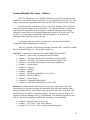
ExtraNET Avalanche
Overview:
Avalanche acquires data from a RTU and sends it to the customer in he form of an
email. This is useful in applications which log data at pre-determined intervals and
report back to a host periodically. This addresses many of the common coverage
problems that can be encountered with a LEO satellite constellation and can be
particularly useful in areas with a limited view of the sky. Arranging a transmission to
take place when you have data can significantly reduce airtime costs incurred due to
incomplete connection attempts and the robustness of the Avalanche when actually
sending the data. It eliminates the need for a host system to continually retry a data
connection if satellite coverage is not available at the remote site during the connection
attempt.
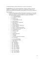
Features:
•
•
•
•
•
•
•
•
•
•
•
•
•
•
•
On-site storage of data
Fully customizable scheduled polling and reporting
Can be polled remotely using free SMS messages
Security available for SMS messages
Data can be delivered to any email address as an attachment in either
binary format or as a convenient comma delimited CSV file.
With scheduled reporting, the modem can be put to sleep between
connections to save power.
Support for industry standard GFM protocols such as Modbus, Enron
Modbus and the Fisher ROC.
Special advanced features when used with Emerson / Fisher FloBoss
Support for MODBUS RTU protocol
Pollable and remotely configurable
RS232 or RS485 Interface to RTU
Online data available at http://www.MeterStar.com
Optionally available with restricted access through the use of a VPN direct
to Globalstar
Menu driven configuration system using a simple ASCII terminal
Special airtime plans may apply
27
Theory of Operation
Avalanche is built around the ExtraNET CC platform. This platform includes the
management of the QUALCOMM GSP-1620 or GSP-1720 modem. This integration
includes power control over the modem, SMS messages, and satellite status among other
features.
When Avalanche is initially powered on it will first try to determine the current
time. This requires that a Globalstar satellite capable of transmitting on the S band be
overhead. You may also access the menu and perform configuration and maintenance
using the diagnostic cable at this time. It will stay awake for approximately 3 minutes
after it obtains the time while checking the satellite for any over the air configuration
changes.
If you have turn on the “Check for SMS messages” then the unit will stay awake
indefinitely. Every 10 seconds it checks to see if there are any new commands that have
been sent via SMS. SMS messages are unique in the way they are handled in the
Globalstar network. When you send a SMS message, Globalstar first looks to see if the
unit is registered on any of the gateways. If it is, the message is sent immediately. If the
message is not successful for any reason, Globalstar goes through a retry algorithm until
the unit does register and the message is sent successfully.
Because SMS messages can be sent by anybody using the Globalstar web site,
you can turn on the Advantage “SMS Security”. When the security is turned on,
Advantage requires a special key to be sent with each SMS message. The key is unique
for every device and changes frequently. In addition to the security, there is a very
limited set of commands which must be in exactly the proper form before anything will
happen on Advantage.
If you have configured the unit to NOT check for SMS messages then Avalanche
will go into a very low power mode requiring only about 10 mA to operate. In the low
power mode only the time of day clock and scheduler are left operational. Every 10
seconds the scheduler will check to see if it is time to poll the RTU.
Three different protocols are supported, MODBUS, ENRON Modbus, and the
Fisher ROC protocol. In the MODBUS mode you must configure Avalanche with up to
20 different RTU MODBUS addresses, each capable of polling up to 20 different 32 bit
IEEE 754 floating point registers. Each entry allows for a different interval to be used.
A typical application might be to read daily records once per day, hourly records
once per hour, and perhaps plunger records once every minute. For each poll, Avalanche
timestamps the data and keeps it in non-volatile memory.
ENRON Modbus is a derivative of MODBUS that defines certain registers that
can be read as lists of data items. This is done to support the API 21.1 requirement for
hourly and daily logs (and others). Each manufacture of devices that are sold as ENRON
28
Modbus may actually define a different number of items to be returned and what these
items are when the special registers are read. Please check with Crystalline Technology
to determine if the RTU you desire to use with Avalanche is supported. Currently we
support ENRON Modbus as delivered by Barton™ and Control Microsystems
Incorporated ™.
If the Fisher ROC protocol is selected, Avalanche gathers data in accordance to
the API 21.1 guidelines for custody transfer. Avalanche reads the first 12 columns of the
Daily and Hourly archives, 4 columns from the extended archive, current values for all of
the logged registers, the 42 configuration parameters, and the event log. The
configuration and events are only sent if they are new.
In addition, the FloBoss is monitored for any RBX originated messages. Upon
reception, Avalanche will immediately poll the FloBoss for all the data and send the
results to the specified host.
The scheduler is defined during the setup process. You have the ability of
sending the acquired data at any interval or at preset times. We strongly suggest at least
one report be sent shortly after contract hour. Additional reports can be sent to meet
operational requirements.
For FloBoss and most MODBUS applications, the data can be sent to the host
very quickly, requiring only about 15 seconds of airtime. We offer service plans
designed to fit your reporting requirements.
Data is sent to the host as a file attachment in an email. This attachment can be
either a binary file or a CSV file. Note, only the CSV file contains all the data required to
meet stringent API 21.1 requirements. Because of the overhead in maintaining the
connection to the server, there is not a significant difference in cost in airtime between
the two different formats. The binary file is maintained for legacy systems or special
MODBUS applications only.
The SMTP server can be the customers, Globalstar’s, or one at Crystalline
Technology. Because the time required to work the email server is charged against the
Globalstar air time, it is important to have a fast server. For additional security,
Avalanche can be provisioned for use on a private subnet. These networks are restricted
to prohibit outside access and require a VPN (Virtual Private Network) connection direct
to a Globalstar gateway.
Avalanche is a complete TCP/IP node on the network. There is no database or
processing of the data on the network. All traffic is routed using traditional “internet”
techniques and not “massaged” in any way by any system along the way. This provides a
high degree if data integrity.
For users who would like the benefit of a complete turn-key system, data can be directed
to www.MeterStar.com.
29
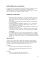
Getting Ready to use Avalanche
Avalanche utilizes the Globalstar Low Earth Orbit (LEO) satellite constellation. Since
the satellites are in constant motion they will provide coverage where other
communications may fail. Even still, to obtain the best possible coverage, you should
select a site that has a clear and unobstructed view of the sky.
Installation Considerations
•
•
•
•
•
•
With heavy foliage you may need to move away from the foliage, remove some
foliage, or try to get above the foliage. Avalanche works with a limited view of
the sky but a better view will result quicker acquisition and thus lower power
requirements.
There should be no other equipment blocking any part of the sky including the
mast it is mounted on.
Avalanche contains mounting hardware suitable for a 2” to 2 ½” conduit mast.
The mast should be firmly supported to withstand wind, rain, snow, and ice
storms which might occur in your area.
If Solar Panels are used, they should be located BELOW the Avalanche to avoid
obstructing the view of the sky.
Avalanche is rated for service in Class 1, Division 1 locations. The appropriate
wiring techniques must be employed to avoid compromising this rating. Please
see Appendix A.
The specification for RS-232 calls for a maximum distance of 50 feet at 20Kbps
and the RS-422/485 specification calls for a maximum of 5000 feet at 9600Bps.
Data rates are a function of the distance of the cable. The shorter the cable length
the higher the data rate that one can achieve. A high quality shielded cable should
be used.
Interfacing RTU
J1 (center left) is a 5 pin Phoenix™ connector for interfacing to customer supplied
equipment. This interface is user selectable during configuration for RS232 or RS485
levels. When configured for RS485 a full duplex 4 wire interface is supported. The
ExtraNET CC has a 100 ohm termination resistor on the receive lines.
For RS485:
Pins 1 and 2 is the receive data (data sent to the ExtraNET CC)
Pins 3 and 4 are transmit data (data sent from the ExtraNET CC)
Pin 5 is ground
For RS232:
Pin 1 is receive data (data sent to the ExtraNET CC)
Pin 3 is transmit data (data sent from the ExtraNET CC)
30
Pin 5 is ground
(Pins 2 and 4 are not supported when configured as RS232)
J3 (bottom left) is shared with J1 and is the RS232 interface to customer equipment. The
function of J3 is shared with the 5 pin Phoenix connector labeled J1 (middle left). Please
reference the table below for pin definitions of the DB9F J3 connector. This connector
does not strictly conform to RS-232 standards and caution is recommended to avoid
damage to the ExtraNET CC. This connector shares function with J1 and is only valid
when ExtraNET CC is configured for RS-232. When RS-485 is selected you should use
J1 and leave J3 disconnected:
(J3 Interface - RS232 Customer Interface)
Pin 1
Pin 2
Pin 3
Pin 4
Pin 5
Pin 6
Pin 7
Pin 8
Pin 9
DCD Output (0 to 5 Volts)
TX Data (RS-232)
RX Data (RS-232)
DTR Output (0 to 5 Volts)
Ground
DSR Output (0 to 5 Volts)
CTS Output (RS-232)
RTS Input (RS-232)
+8 Volts (Very Low Power)
31
Avalanche Menu and Configuration
You need an ASCII terminal such as a Laptop running terminal software like Windows,
Hyper Terminal or SIOW. Using the diagnostic cable, connect the green 10 pin phoenix
connector to the processor board and the DB9-F connector to your computer’s serial port.
Connect to the unit at 9600 baud, 8 bits no parity and press the spacebar.
SIOW is a program that provides a terminal interface that is quick and easy to use. You
can download the program from our web site at:
http://www.Crystalline.us/downloads/ExtraNET/siow.zip
Upon power up, reset, or pressing the space bar, you will be presented with the following
display and menu. The Build number is unique to the version of the program loaded in to
the device.
ExtraNET SF Avalanche
(c) 2005, 2006, & 2007 by Crystalline Technology, Inc
See http://www.ExtraNETCC.com for more information.
Build 2747.42186, Serial# 00000a4d
Current time: 7/10/07 17:20:58
D)
L)
C)
H)
B)
F)
G)
R)
T)
Display Settings
List Event Log
Send Email now
Hangup Globalstar Modem
Reset ExtraNET CC
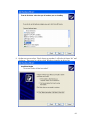
Configure ExtraNET CC Mode
Configure Globalstar Modem
Show Communication Status
Test RTU Connection
D) Display Settings:
Not connected
HEX GSN: 74040B82
Unit is pollable via SMS.
Local timezone is -6 hours from UTC.
SMTP IP Address: 63.247.209.118
SMTP TCP/IP Port: 25
E-Mail To Address: [email protected]
E-Mail From Address: [email protected]
E-Mail Subject: ExtraNET CC Data
No activity timeout: 10
Maximum Connect Time: 300
32
Globalstar baud rate: 9600
Terminal baud rate: 9600
Terminal port configured for RS232
Current Time is 23:22:15 8/29/07 UTC
The Display Settings will provide basic information about the unit’s
configuration. As shown in the above example the unit is configured to be pollable via
SMS, and the time zone is set to UTC -6 which happens to be MST. Also shown is the
email configuration which includes the SMTP server, SMTP port, To Address, From
Address, and Subject. The unit is also configured to automatically hang up the modem if
no data packets are sent for 10 seconds during a connection, and to automatically
disconnect after a maximum of 300 seconds regardless of how much data is being sent.
These features will help to save airtime if an unexpected error occurs. Also shown are
the equipment baud rates and the current time.
For modems with a public dynamically assigned IP address, there are two
different SMTP servers that may be used. The server at 63.247.209.118
(mail.extranetcc.com) is owned and maintained by Crystalline Technology and will trust
any node on the Globalstar network. The server at 65.197.64.252
(smtp.pdn.globalstar.com) is operated by Globalstar and will also trust all Globalstar
nodes. You must specify the actual IP number and not the domain.
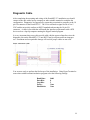
L) List Event Log
List Event Log displays a log of events that can be useful for troubleshooting and
evaluating overall performance. As shown in the example above, the log shows
information about satellite acquisition and loss. It also displays information about when
the unit is transmitting data. If you are having trouble receiving data, the first place to
look is the event log. All entries will have a timestamp as long as the time has been
acquired from the satellite network at least once. The log has the capability of storing the
last 100 events. Old events are automatically deleted as new ones are written. The event
log can be cleared completely with the “F” command.
UTC Date
0/00/00
7/19/07
7/19/07
7/19/07
7/19/07
7/19/07
7/19/07
7/19/07
7/19/07
7/19/07
7/19/07
Time
0:00:00
15:17:25
15:20:15
15:20:38
15:20:45
15:20:58
15:20:58
15:21:03
15:21:31
15:23:32
15:26:13
Event
Connection Timed out
Initialize
Connection Timed out
Automatic Report
Connected
Disconnected
Connection Timed out
Connection Timed out
Satellite lost
Connection Timed out
Satellite Acquired
33
7/19/07
7/19/07
0/00/00
7/19/07
7/19/07
7/19/07
7/19/07
7/19/07
7/19/07
7/19/07
15:26:13
15:26:20
0:00:00
15:26:25
15:36:38
15:38:08
15:42:39
15:43:39
15:48:41
15:49:42
Automatic Report
Connected
Connection Timed out
Initialize
Satellite lost
Satellite Acquired
Satellite lost
Satellite Acquired
Satellite lost
Satellite Acquired
C) Send Email now
Scheduled at 7/12/07 13:40:09
Hangup
Communication successful to FloBoss
MeterTAG 23456
Roc data ready
Establishing Connection CONNECT
MODEM RESP: CONNECTED
Negotiating PPP...
Connected to GlobalStar, IP Address is 10.162.58.159
Starting SMTP
220-clf-smsc1.ss.airtouch.com ESMTP Sendmail
8.13.7+Sun/8.13.7; Thu, 12 Jul 2007
19:40:22 GMT
220 We do not accept UCE.
250 clf-smsc1.ss.airtouch.com Hello [207.176.150.175],
pleased to meet you
250 2.1.0 <[email protected]>... Sender ok
250 2.1.5 <[email protected]>... Recipient ok
E250 2.0.0 l6CJeM49008877 Message accepted for
delivery
E-Mail Sent
E221 2.0.0 clf-smsc1.ss.airtouch.com closing
connection
Message Accepted.
34
Disconnecting
hangup
The “C” command is used during installation and troubleshooting. It will poll the
RTU for the most current data and then schedule a report to be sent via email using the
current settings. The example above shows ExtraNET CC Avalanche polling a Fisher
FloBoss for current data and then transmitting the report. Notice that ExtraNET CC
Avalanche checks to see if coverage is available before attempting to transmit. If
coverage is not available, you will see information from the AT$QCSTATUS command
scroll across the screen repeatedly until the unit can successfully transmit.
If Avalanche is unable to send the email due to a bad email address, SMTP server
address, or a email server failure then Avalanche will disable future attempts to send
email until the problem is corrected. Avalanche will also enter a mode where it stays
awake for 24 hours continually checking for a SMS message that potentially will correct
the problem.
Avalanche will also stay on line looking for a satellite until it is able to send the
message. Proper installation with a good view of the sky will have a direct impact on the
overall performance and the power requirements of Avalanche. This feature makes
ExtraNET CC Avalanche very reliable in areas with little or no view of the sky, and
makes use of any orbiting satellites which may be operating with degraded performance.
H) Hang-up Globalstar Modem
This command is used to force the modem to hang up if it is currently on a phone
call. This is useful for testing and diagnostics.
B) Reset ExtraNET CC
Issuing the “B” command will force the processor to reset. This command is
generally used only if the modem or processor board become erratic during initial testing.
After completing the “F” command, the processor will also reset.
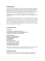
F) Configure ExtraNET CC Mode
This is the command where the entire configuration takes place. Pressing the
return key will advance you to the next configuration option. This can be quite complex
and it is important to have a good idea of how you want to have the unit configured
beforehand. Remember, to go on to the next option, simply press return. This is helpful
if you miss something and need to issue the command again to get back to it.
The setup questions below are shown in Blue followed by an explanation.
35
Number of hours offset from UTC (-5 for EST) (-6)?
The time is acquired from the satellite. This provides a very accurate time
standard which is used to determine when to poll and when to report. Since the
satellite maintains time in the UTC (Universal Time Coordinated). Avalanche
allows you to adjust this to your local time zone. EST is -5, CST is -6, MST is -7,
PST is -8 and so on.
Allow unit to be polled via SMS? (Y) Set (Y)
SMS messages allow a convenient “out of band” method of sending commands
to the Avalanche. If the SMS messages are enabled then the unit will not enter
the low power mode and will stay awake waiting for SMS messages all the time.
This is good if you want a polled solution. The unit will always stay awake for 3
minutes after sending an email allowing commands to be sent during that time.
Enable SMS security? (Y) Set (Y)
SMS messages present a potential security risk since the commands can cause
things to happen, or cause them to quit happening. Avalanche has addressed
this issue with a security that changes daily and is unique to the specific
Avalanche. Enabling security is recommended.
Number of scheduled reports per day? (0) 1
For normal applications you should schedule at least one report per day to occur
after contract hour.
WARNING: Schedule MUST be in increasing chronological
order
and expressed in the configured time zone!
Schedule 1: Hour:Min:Sec (00:00:00) ? 07:00:00
You are entering times that are consistent with the UTC offset entered above.
Enter the complete time in the format shown HH:MM:SS. The scheduler expect
the times to be in the proper order as well. Use a 24 hour format with the times
all in order (05:00:00 before 22:00:00).
Poll slave for Data? 1=No, 3=ROC, 4=Modbus Logger(ROC)
Avalanche will support both the ROC protocol and the MODBUS
RTU protocol. Depending on your selection, you will be
prompted for FloBoss parameters or MODBUS parameters.
ROC Master Group # (3)?
ROC Master Unit # (1)?
Avalanche acts as a ROC master. Although almost any address can be used,
Group 3, Unit 1 is common for the ROCLINK 800 and similar hosts. It is also the
default used with Avalanche.
ROC Remote Group # (240)?
ROC Remote Unit # (240)?
36
This is the address of the FloBoss that is connected to Avalanche. The group
240, unit 240 is a universal poll address for directly connected devices.
Operator ID (LOI)?
Password (1000)?
If you are connected via the LOI port then you must specify a valid user name
and password before access will be granted.
Report as record type (99)?
The record type is returned as part of the email message back to the host. If
several different configurations are in use for different FloBoss units then the
record type can be used to identify the type of data contained in the email. This
is particularly useful for binary messages.
SMTP IP Address is 63.247.209.118
Change IP address (N)? , Enter new address:
BYTE0: 65
BYTE1: 197
BYTE2: 64
BYTE3: 252
WARNING: There are two public email servers (SMTP) that are available for
use with Avalanche. 63.247.209.118 (mail.extranetcc.com) operated by
Crystalline Technology and 65.197.64.252 (smtp.pdn.globalstar.com) both
are configured to accept messages from within the Globalstar network. For
devices configured with a static IP, you will need to provide the address of
your server.
SMTP PORT (25):
WARNING: Port 25 is the standard port used for SMTP mail servers.
Change this only if you have a mail server that operates on a different, not
standard port.
E-Mail To Address ([email protected]):
E-Mail From Address ([email protected]):
E-Mail Subject (ExtraNET CC Data):
WARNING: The email To, From, and Subject lines are configured here.
Please note, if you provide a invalid email address (or SMTP server above),
it will be impossible to send the data and may result in a unit that is totally
non-functional without a field visit to correct the configuration.
Send attachment as binary? (Y) or CSV (N)? (N) Set (N)
Data can be returned in the email as standard CSV (comma delimited file) or as
a binary file.
Maximum amount of NO ACTIVITY time (10 seconds)?
Absolute maximum time allowed for connection? (300)
37
For Avalanche these parameters should not be changed without consultation
with Crystalline Technology.
Use RS232 (Y) or RS485 (N)? (Y) Set (Y)
The interface used to communicate with the RTU supports both an RS-232 and a
RS-485 style interface. You must match the selection with the interface on the
RTU.
Baud Rate for local Terminal / RTU (9600)?
9600 baud is highly recommended unless you have an RTU that will not operate
at this baud rate.
Clear event log? (contains 250 events) (Y)
Setup Complete, Restarting
After completing the configuration, Avalanche will perform a reset so all the new
setting will take effect.
Email Attachment Formats
Binary File - FloBoss
Selecting the “Binary” file format will cause Avalanche to send the attachment as
a binary “ATT” file. This file must be parsed with a user supplied program. For
purposes of sending the data using e-mail, the data is mime BASE64 encoded in
accordance to RFC2045
// RFC2045 describes the mime base64 encoding that allows
// transfer of binary data through an ASCII channel.
Table 1: The Base64 Alphabet
Value Encoding
0 A
1 B
2 C
3 D
4 E
5 F
6 G
7 H
8 I
9 J
10 K
11 L
12 M
13 N
14 O
15 P
16 Q
Value Encoding
17 R
18 S
19 T
20 U
21 V
22 W
23 X
24 Y
25 Z
26 a
27 b
28 c
29 d
30 e
31 f
32 g
33 h
Value Encoding
34 i
35 j
36 k
37 l
38 m
39 n
40 o
41 p
42 q
43 r
44 s
45 t
46 u
47 v
48 w
49 x
50 y
Value Encoding
51 z
52 0
53 1
54 2
55 3
56 4
57 5
58 6
59 7
60 8
61 9
62 +
63 /
(pad) =
38
//See a definition of the mapping requirement at the following URL:
//http://www.cse.ohio-state.edu/cgi-bin/rfc/rfc1521.html#sec-5.2
// The record structure for doing a binary file attachment
// the structure “assumes” that you are using a properly defined
// configuration in the FloBoss
typedef
ieee
ieee
ieee
ieee
ieee
ieee
ieee
ieee
ieee
ieee
ieee
ieee
ieee
ieee
ieee
ieee
} API;
struct _API{
Time;
FlowTime;
Hw;
Pf;
Tf;
IMV;
hwpf;
Vol;
Energy;
BTU;
SG;
CO2;
N2;
MaxHw;
MinHw;
MinBatt;
typedef union _history{
api byName;
ieee v[16];
} History; // record is 64 bytes long
typedef struct {
int
Message_Type;
//
//
int32
RTU_ID;
//
//
ieee
Analog1;
//
ieee
Analog2;
//
ieee
Analog3;
//
int32
TOD;
//
History
Daily;
//
History
Hourly[24];
//
//
} _rocdata; // record is 1621 bytes long
specified during
configuration
a 32 bit RTU Tag # (must be
numeric)
FloBoss Analog1
FloBoss Analog2
FloBoss Analog3
Genesis is 1/1/2000
16 values from daily archive
16 values from the hourly /
Extended archive
A sample file:
offset data
description
00000
00001
63
A0 5B 00 00
00005
00009
0000D
00 00 20 41
00 00 A0 41
1A D0 E6 40
//
//
//
//
//
//
Message Type
RTU_ID (Big Ended, word reversed Intel format)
23456
Analog1 (IEEE754) 10.0
Analog2 (IEEE754) 20.0
Analog3 (IEEE754) 7.2129
39
00011
00015
00019
0001D
00021
00025
00029
0002D
00031
00035
00039
0003d
00041
00045
00049
0004d
00051
00055
00059
0005d
00061
00065
00069
0006d
00071
00075
00079
0007d
00081
00085
00089
0008d
00091
00095
00099
0009d
000A0
000B0
000C0
000D0
000D5
000E0
000F0
00100
00110
00115
00120
00130
00140
00150
00155
00160
00170
00180
00190
0019d
001A0
001B0
001C0
001D0
001d5
001E0
001F0
76
00
00
00
00
00
F2
56
B6
7E
00
00
00
00
53
00
00
00
00
00
00
00
F2
56
24
54
00
00
00
00
00
00
00
00
00
00
42
43
00
00
00
42
43
00
00
00
42
43
00
00
00
42
43
00
00
00
42
43
00
00
00
42
43
58
0A
00
00
80
00
EE
DA
33
87
00
00
00
00
4E
00
00
0C
00
00
80
00
EE
DA
CD
5A
00
00
00
00
00
00
00
0D
00
00
00
24
00
00
0E
00
24
00
00
0F
00
24
00
00
10
00
24
00
00
11
00
24
00
00
12
00
24
C4
1E
B4
70
BB
82
D5
18
C4
C9
00
00
00
00
27
00
00
1D
70
70
BB
82
D5
18
82
86
00
00
00
00
00
00
00
1D
70
70
80
CD
00
00
1D
80
CD
00
00
1D
80
CD
00
00
1D
80
CD
00
00
1D
80
CD
00
00
1D
80
CD
08
08
44
42
43
42
44
43
45
45
00
00
00
00
01
00
00
08
42
42
43
42
44
43
43
43
00
00
00
00
00
00
00
08
42
// TOD (#seconds since 1/1/200)
// Daily (MM:HH DD:MM) Sept 30, 10:00 AM
// Daily Flow time (minutes) 1440.0
// Daily average Hw 60.0
// Daily average Pf 375.0
// Daily average Tf 65.0
// Daily IMV 1711.467
// Daily hwpf 152.8529
// Daily Volume 6278.464
// Daily Energy 6448.937
// Daily Column 9 0.0
// Daily Column 10 0.0
// Daily Column 11 0.0
// Daily Column 12 0.0
// Calculated Minimum Extended Column 1 3E-38
// Calculated Maximum Extended Column 2 0.0
// Calculated Minimum Extended Column 3 0.0
// Hourly Time Stamp Sept 29, 12:00 PM
// Hourly Flow Time 60.0
// Hourly average hw 60.0
// Hourly average Pf 375.0
// Hourly average Tf 60.0
// Hourly IMV 1711.467
// Hourly hwpf 152.8529
// Hourly Volume 261.6027
// Hourly Energy 268.7057
// Hourly column 9 0.0
// Hourly column 10 0.0
// Hourly column 11 0.0
// Hourly column 12 0.0
// Extended column 1 0.0
// Extended column 2 0.0
// Extended column 3 0.0
// Hourly record #2 time stamp
// Hours 2 through 24 repeat the format described
// above…
BB 43 00 00 82 42 F2 EE D5 44 56 DA 18
82 43 54 5A 86 43 00 00 00 00 00 00 00
00 00 00 00 00 00 00 00 00 00 00 00 00
00 00
08 00 00 70 42 00 00 70
// Hour 3
BB 43 00 00 82 42 F2 EE D5 44 56 DA 18
82 43 54 5A 86 43 00 00 00 00 00 00 00
00 00 00 00 00 00 00 00 00 00 00 00 00
00 00
08 00 00 70 42 00 00 70
// Hour 4
BB 43 00 00 82 42 F2 EE D5 44 56 DA 18
82 43 54 5A 86 43 00 00 00 00 00 00 00
00 00 00 00 00 00 00 00 00 00 00 00 00
00 00
08 00 00 70 42 00 00 70
// Hour 5
BB 43 00 00 82 42 F2 EE D5 44 56 DA 18
82 43 54 5A 86 43 00 00 00 00 00 00 00
00 00 00 00 00 00 00 00 00 00 00 00 00
00 00
08 00 00 70 42 00 00 70
// Hour 6
BB 43 00 00 82 42 F2 EE D5 44 56 DA 18
82 43 54 5A 86 43 00 00 00 00 00 00 00
00 00 00 00 00 00 00 00 00 00 00 00 00
00 00
08 00 00 70 42 00 00 70
// Hour 7
BB 43 00 00 82 42 F2 EE D5 44 56 DA 18
82 43 54 5A 86 43 00 00 00 00 00 00 00
40
00200
00210
00215
00220
00230
00240
00250
00255
00260
00270
00280
00290
0029f
002A0
002B0
002C0
002D0
002D5
002E0
002F0
00300
00310
00315
00320
00330
00340
00350
00355
00360
00370
00380
00390
00395
003A0
003B0
003C0
003D0
003D5
003E0
003F0
00400
00410
00415
00420
00430
00440
00450
00455
00460
00470
00480
00490
00495
004A0
004B0
004C0
004D0
004D5
004E0
004F0
00500
00510
00515
00
00
00
42
43
00
00
00
42
43
00
00
00
42
43
00
00
00
42
43
00
00
00
42
43
00
00
00
42
43
00
00
00
42
43
00
00
00
42
43
00
00
00
42
43
00
00
00
42
43
00
00
00
42
43
00
00
00
42
43
00
00
00
00
00
13
00
24
00
00
14
00
24
00
00
15
00
24
00
00
16
00
24
00
00
17
00
24
00
00
00
00
24
00
00
01
00
24
00
00
02
00
24
00
00
03
00
24
00
00
04
00
24
00
00
05
00
24
00
00
06
00
24
00
00
07
00
00
1D
80
CD
00
00
1D
80
CD
00
00
1D
80
CD
00
00
1D
80
CD
00
00
1D
80
CD
00
00
1E
80
CD
00
00
1E
80
CD
00
00
1E
80
CD
00
00
1E
80
CD
00
00
1E
80
CD
00
00
1E
80
CD
00
00
1E
80
CD
00
00
1E
00
00
08
BB
82
00
00
08
BB
82
00
00
08
BB
82
00
00
08
BB
82
00
00
08
BB
82
00
00
08
BB
82
00
00
08
BB
82
00
00
08
BB
82
00
00
08
BB
82
00
00
08
BB
82
00
00
08
BB
82
00
00
08
BB
82
00
00
08
00
00
00
43
43
00
00
00
43
43
00
00
00
43
43
00
00
00
43
43
00
00
00
43
43
00
00
00
43
43
00
00
00
43
43
00
00
00
43
43
00
00
00
43
43
00
00
00
43
43
00
00
00
43
43
00
00
00
43
43
00
00
00
00 00 00 00 00 00 00 00 00 00 00
00
00
54
00
70
00
5A
00
42
82
86
00
00
42
43
00
00
F2
00
00
70
EE D5 44 56 DA 18
00 00 00 00 00 00
00 00 00 00 00 00
// Hour 8
00
00
54
00
70
00
5A
00
42
82
86
00
00
42
43
00
00
F2
00
00
70
EE D5 44 56 DA 18
00 00 00 00 00 00
00 00 00 00 00 00
// Hour 9
00
00
54
00
70
00
5A
00
42
82
86
00
00
42
43
00
00
F2
00
00
70
EE D5 44 56 DA 18
00 00 00 00 00 00
00 00 00 00 00 00
// Hour 10
00
00
54
00
70
00
5A
00
42
82
86
00
00
42
43
00
00
F2
00
00
70
EE D5 44 56 DA 18
00 00 00 00 00 00
00 00 00 00 00 00
// Hour 11
00
00
54
00
70
00
5A
00
42
82
86
00
00
42
43
00
00
F2
00
00
70
EE D5 44 56 DA 18
00 00 00 00 00 00
00 00 00 00 00 00
// Hour 12
00
00
54
00
70
00
5A
00
42
82
86
00
00
42
43
00
00
F2
00
00
70
EE D5 44 56 DA 18
00 00 00 00 00 00
00 00 00 00 00 00
// Hour 13
00
00
54
00
70
00
5A
00
42
82
86
00
00
42
43
00
00
F2
00
00
70
EE D5 44 56 DA 18
00 00 00 00 00 00
00 00 00 00 00 00
// Hour 14
00
00
54
00
70
00
5A
00
42
82
86
00
00
42
43
00
00
F2
00
00
70
EE D5 44 56 DA 18
00 00 00 00 00 00
00 00 00 00 00 00
// Hour 15
00
00
54
00
70
00
5A
00
42
82
86
00
00
42
43
00
00
F2
00
00
70
EE D5 44 56 DA 18
00 00 00 00 00 00
00 00 00 00 00 00
// Hour 16
00
00
54
00
70
00
5A
00
42
82
86
00
00
42
43
00
00
F2
00
00
70
EE D5 44 56 DA 18
00 00 00 00 00 00
00 00 00 00 00 00
// Hour 17
00
00
54
00
70
00
5A
00
42
82
86
00
00
42
43
00
00
F2
00
00
70
EE D5 44 56 DA 18
00 00 00 00 00 00
00 00 00 00 00 00
// Hour 18
00
00
54
00
70
00
5A
00
42
82
86
00
00
42
43
00
00
F2
00
00
70
EE D5 44 56 DA 18
00 00 00 00 00 00
00 00 00 00 00 00
// Hour 19
00 70 42 00 00 70
// Hour 20
41
00520
00530
00540
00550
00555
00560
00570
00580
00590
00595
005A0
005B0
005C0
005D0
005D5
005E0
005F0
00600
00610
00615
00620
00630
00640
00650
42
43
00
00
00
42
43
00
00
00
42
43
00
00
00
42
43
00
00
00
42
43
00
00
00
24
00
00
08
00
24
00
00
09
00
24
00
00
0A
00
24
00
00
0B
00
24
00
00
80
CD
00
00
1E
80
CD
00
00
1E
80
CD
00
00
1E
80
CD
00
00
1E
80
CD
00
00
BB
82
00
00
08
BB
82
00
00
08
BB
82
00
00
08
BB
82
00
00
08
BB
82
00
00
43
43
00
00
00
43
43
00
00
00
43
43
00
00
00
43
43
00
00
00
43
43
00
00
00 00 82 42 F2 EE D5 44 56 DA 18
54 5A 86 43 00 00 00 00 00 00 00
00 00 00 00 00 00 00 00 00 00 00
00
00
54
00
70
00
5A
00
42
82
86
00
00
42
43
00
00
F2
00
00
70
EE D5 44 56 DA 18
00 00 00 00 00 00
00 00 00 00 00 00
// Hour 21
00
00
54
00
70
00
5A
00
42
82
86
00
00
42
43
00
00
F2
00
00
70
EE D5 44 56 DA 18
00 00 00 00 00 00
00 00 00 00 00 00
// Hour 22
00
00
54
00
70
00
5A
00
42
82
86
00
00
42
43
00
00
F2
00
00
70
EE D5 44 56 DA 18
00 00 00 00 00 00
00 00 00 00 00 00
// Hour 23
00
00
54
00
70
00
5A
00
42
82
86
00
00
42
43
00
00
F2
00
00
70
EE D5 44 56 DA 18
00 00 00 00 00 00
00 00 00 00 00 00
// Hour 24
42
Comma Delimited File Format – FloBoss
The CSV file format is a user friendly format that can easily be loaded into most
databases such as MS Sql, MySql, and Access, or in to spread sheets such as Excel. Each
string is encapsulated in quotation marks and each data field is separated with a comma.
For both the Daily and Hourly records, zeros will be included if the user has not
defined the optional columns as described below. The optional columns are included to
support special requirements such as logging of casing and tubing pressure, perhaps
compressor status, tank levels, and other operational sensors can be used as well. This
provides a very high degree of flexibility while maintaining a very simple and
standardized data reporting system to be used.
It is suggested that you match a “record type” to an user defined FloBoss
configuration when configuring the Avalanche.
There are 6 possible record formats included with each email. Column A contains
the record format for that row. The possible formats are:
Node Info: (contains basic information about the FloBoss and ExtraNET)
• Column B – Time record was acquired from the FloBoss
• Column C – The unique Electronic Serial Number of the ExtraNET
• Column D – The Meter Tag number from the FloBoss (point 41,0,0)
• Column E – User defined format type as set during configuration
• Column F – Contract Hour
• Column G – Analog 1
• Column H – Analog 2
• Column I – Analog 3
• Column J – SMS Security Enabled (1=Yes, 0=No)
• Column K – Model (4=FB103)
• Column L – Station Name
• Column M – Avalanche Build Number
• Column N – RBX Occurred Indicator (1=Yes, 0=No)
Definitions: (contains header names for the current, daily, and hourly records) The
header names are derived by reading the definition of the hourly and extended tables
directly from the Floboss. The numbers represented in the CSV file are the basic TLP
identifiers used to define the points being logged. The first 8 are always fixed by the
FloBoss to meet the minimum API 21.1 requirements. The additional registers are user
defined. The first 8 normally are defined, the remaining 7 are user defined:
•
•
•
Column B - Date and Time for the record
Column C - TLP 42,0,6 - Flow Time (minutes)
Column D - TLP 10,0,0 – Flow averaged differential pressure
43
•
•
•
•
•
•
•
•
•
•
•
•
•
Column E - TLP 10,0,1 – Flow averaged static line pressure
Column F - TLP 10,0,2 – Flow averaged gas temperature
Column G - TLP 10,0,10 – IMV/BMV (C prime)
Column H - TLP 10,0,9 – Flow Extension (∑√(HwPf))
Column I - TLP 10,0,3 – Accumulated Volume (MCF)
Column J - TLP 10,0,4 – Accumulated Energy (MMBTU)
Column K - User Defined History Point 9
Column L - User Defined History Point 10
Column M - User Defined History Point 11
Column N - User Defined History Point 12
Column O - User Defined Extended History Point 1
Column P - User Defined Extended History Point 2
Column Q - User Defined Extended History Point 3
Current: (snap shot) After reading the definitions above, Avalanche then polls each one
of the TLP points to see what the current reading is. Thus, if you are logging average Hw
(differential pressure) in the hourly history, you will see a entry in the “Current:” row that
has the instantaneous Hw at the time the data was polled from the FloBoss
Daily: The first 12 columns of the Daily archive are returned of the most recent record in
the archive. This is the record for the previous day.
• Column B – Month, Day, Hour, and Minute of record. Microsoft Excel
automatically interprets this data for the correct year.
• Columns C to J are the first 8 default data items logged by the FloBoss which are
in compliance with API21.1
• Columns K to N are the next 4 user defined columns in the Daily Archive
• Column O is the minimum of the first column in the Extended archive for the
most recent 24 hours. This is useful for recording things like the minimum
differential pressure experienced over the last 24 hours.
• Column P is the maximum of the second column in the Extended archive for the
most recent 24 hours. This could record things such as the maximum differential
pressure experienced over the last 24 hours.
• Column Q is the minimum of the third column in the Extended archive for the
most recent 24 hours. Typically this would be minimum battery voltage over the
last 24 hours.
Hourly: The most recent 24 hourly records read from the Hourly and Extended archives.
The first 8 columns of the hourly archive are defined by the FloBoss to be in accordance
to API 21.1 guidelines. An additional 4 user defined columns are included along with the
first 3 columns of the Extended archive.
Event: Due to the very comprehensive and compact recording of events in the FloBoss,
Avalanche simply reads all the new events and sends them as ASCII encoded hex. It is
up to the user to decode these events in accordance to the ROC Protocol Users Manual
available from Emerson / Fisher.
44
Avalanche maintains a pointer so that only new events are sent each time.
Configuration: Any time that the configuration is changed, Avalanche will send a
complete new configuration back to the host. This configuration contains some 42
different items that have been identified as having affect over the way that volumes are
being calculated.
• Columns B through AQ correlate to Point Type 46, parameters 2 to 43 in order.
Please refer to the ROC Protocol User Manual for more information on how to
decode these numbers. Any binary (BIN) are encoded as ASCII HEX.
o B = Calculation Method
o C = Calculation Method II
o D = Options
o E = Contract Hour
o F = Integral Multiplier Period
o G = Pipe Diameter
o H = Pipe Reference Temperature
o I = Pipe Material
o J = Orifice Diameter
o K = Orifice Reference Temperature
o L = Orifice Material
o M = Base or Contract Pressure Base
o N = Base or Contract Temperature Base
o O = Atmospheric Pressure
o P = Specific Gravity
o Q = Heating Value
o R = Viscosity
o S = Specific Heat Ratio
o T = Elevation
o U = Latitude
o V = Local Gravitational Acceleration
o W = N2 Nitrogen
o X = CO2 Carbon Dioxide
o Y = H2S Hydrogen Sulfide
o Z = H2O Water
o AA = He Helium
o AB = CH4 Methane
o AC = C2H6 Ethane
o AD = C3H8 Propane
o AE = C4H10 n-Butane
o AF = C4H10 i-Butane
o AG = C5H12 n-Pentane
o AH = C5H12 i-Pentane
o AI = C6H14 n-Hexane
o AJ = C7H16 n-Heptane
o AK = C8H18 n-Octane
45
o
o
o
o
o
o
AL = C9H20 n-Nonane
AM = C10H22 n-Decane
AN = O2 Oxygen
AO = CO Carbon Monoxide
AP = H2 Hydrogen
AQ = Low hw Cutoff
46
Comma Delimited File Format – RealFLO™
Avalanche can be ordered specifically to address the Control Microsystems RealFLO™
equipped gas flow computer. The CSV file format for the RealFLO is very much like the
Emerson FloBoss™ with differences in the order in which the daily and hourly data
appears as the most significant change.
Node Info: (contains basic information about the FloBoss and ExtraNET)
• Column B – Time record was acquired from the FloBoss
• Column C – The unique Electronic Serial Number of the ExtraNET
• Column D – The Meter Run 1 ID from the RealFLO (registers 3167 to 3198)
• Column E – User defined format type as set during configuration normally 105
• Column F – Contract Hour
• Column G – Current Flow Rate (7241)
• Column H – Accumulated volume (7244)
• Column I – Reserved
• Column J – SMS Security Enabled (1=Yes, 0=No)
• Column K – Model (41=RealFLO)
• Column L – Station Number (registers 3020 to 3027)
• Column M – Avalanche Build Number
• Column N – Always 0 for RealFLO
Current: (snap shot) Avalanche polls a series of registers to provide a snap shot of the
current flowing conditions:
• Column B – Flow time current day (7240)
• Column C – Flow Rate (7226)
• Column D – Flow Energy Rate (7228)
• Column E – Flow Extension (7229)
• Column F – Temperature (7220)
• Column G – Line Pressure (7221)
• Column H – Differential Pressure (7222)
• Column I – Volume thus far today (7241)
• Column J - Mass thus far today (7242)
• Column K – Accumulated Volume (7242)
• Column L – Reserved
• Column M – Reserved
•
Daily: The first 12 columns of the Daily archive are returned of the most recent record in
the archive. This is the record for the previous day. This is from the Enron register array
at register 702 for the first run.
• Column B – Date and time for this record from the first two columns read at 702
• Column C – Flow Time in minutes (third column from 702)
• Column D – Volume (fourth column from 702)
47
•
•
•
•
•
•
•
•
Column E – Energy (fifth column from 702)
Column F – Flow Extension (sixth column from 702)
Column G – Flow averaged temperature (seventh column from 702)
Column H – Flow averaged line pressure (eighth column from 702)
Column I – Flow averaged differential pressure (ninth column from 702)
Column J – Volume (MCF) (tenth column from 702)
Column L – Mass (eleventh column from 702)
Column M – Relative Density (twelfth column from 702)
Hourly: The most recent 24 hourly records read from the Hourly array located at 701 for
the first meter run. The data is itemized in the same order as the Daily records.
Configuration: Any time that the configuration is changed, Avalanche will send a
complete new configuration back to the host. This configuration contains some 42
different items that have been identified as having affect over the way that volumes are
being calculated.
• B = Calculation Method (7101)
• C = Calculation Method II (7102)
• D = Options (7146)
• E = Contract Hour (7147)
• F = Reserved
• G = Pipe Diameter (7155)
• H = Pipe Reference Temperature (7156)
• I = Pipe Material (7152)
• J = Orifice Diameter (7153)
• K = Orifice Reference Temperature (7154)
• L = Orifice Material (7151)
• M = Base or Contract Pressure Base (7149)
• N = Base or Contract Temperature Base (7148)
• O = Atmospheric Pressure (7145)
• P = Specific Gravity (7214)
• Q = Heating Value (7217)
• R = Viscosity (7158)
• S = Specific Heat Ratio (7157)
• T = Elevation (7250)
• U = Latitude (7251)
• V = Reserved
• W = N2 Nitrogen (7194)
• X = CO2 Carbon Dioxide (7195)
• Y = Reserved
• Z = Reserved
• AA = Reserved
• AB = CH4 Methane (7193)
48
•
•
•
•
•
•
•
•
•
•
•
•
•
•
•
AC = C2H6 Ethane (7196)
AD = C3H8 Propane (7197)
AE = C4H10 n-Butane (7204)
AF = C4H10 i-Butane (7203)
AG = C5H12 n-Pentane (7206)
AH = C5H12 i-Pentane (7205)
AI = C6H14 n-Hexane (7207)
AJ = C7H16 n-Heptane (7208)
AK = C8H18 n-Octane (7209)
AL = C9H20 n-Nonane (7210)
AM = C10H22 n-Decane (7211)
AN = O2 Oxygen (7202)
AO = CO Carbon Monoxide (7201)
AP = H2 Hydrogen (7200)
AQ = Low hw Cutoff (9614)
49
SMS Messages
SMS (Short Message Service) is a method of sending short ASCII commands to the
ExtraNET Avalanche. SMS messages are typically used as a method of sending text
messages to telephones. In the case of Avalanche they present some quite interesting
attributes.
•
•
•
•
They are available with most Globalstar gateways and always available if you
roam from a US or Canada account.
SMS messages allow 30 to 35 bytes or more of text (varies according to the home
system the unit is subscribed).
SMS messages are queued until the unit has satellite coverage and registers on a
gateway.
SMS messages are FREE and can be sent from any Globalstar SMS portal. See
http://globalstarusa.com/en/services/enhancedservices/g2sms.php
Since it is so easy to send SMS messages, Avalanche has a method of securing the
message. Turn on the SMS security during configuration and Avalanche will only
respond to SMS messages that have a special security code attached to the message. The
security code is different for each unit and changes every day.
Avalanche can be configured to check for SMS messages at all times (at the cost of
increased power consumption) or only after it has sent an email. Since most Avalanche
devices are configured to send an e-mail at least once per day and the gateway will queue
the message, there is always an opportunity to issue commands, if you are not in a hurry.
A special application is provided by Crystalline Technology to facilitate sending of
messages. You can download the utility from
http://www.Crystalline.us/downloads/ExtraNET/SMS/Poll_ExtraNET.zip and run the
setup program to install it on your computer.
The first time you use the Poll_ExtraNET program you should set your host IP
address. It will retain this for future use. In order for Poll_ExtraNET to work, the
computer it is used on must have access to the Internet. The program automates the
process normally required to send an SMS message from the www.Globalstarusa.com
web site.
The Poll_ExtraNET program works with all models of ExtraNET. You can enter a
phone number for the ExtraNET if known, or you can enter the IP if it is using a static IP
address. For units that are configured for “secure SMS” you must know the HEX ESN
(Electronic Serial Number) of the unit you are sending the message to. The HEX ESN is
found on a label on the QUALCOMM modem.
50
The email that is sent to the host contains the ESN as well if you are using the
FloBoss data collection. If you are using the MODBUS then you may contact us for
more information.
ExtraNET SMS Commands that are supported are as shown below:
IP:0.0.0.0
If the unit is an ExtraNET CC then a connection will be made back to the host
with the corresponding IP address using the TCP port that was specified during
the setup.
Avalanche, upon receive of a message with the IP: command and the proper
security if enabled, will cause the unit to send a report now. If the unit is
configured for a FloBoss then new data will be collected before it transmits. If
the unit is configured as a Modbus Logger then it will send what ever data has
been collected up to this time.
WRITEE:xxxx:xx,xx,xx
This command allows writing directly to the configuration memory. It should not
be used with out explicit instructions from Crystalline Technology. Writing
incorrect data to the configuration can leave your unit in a non-functioning state
requiring that the firmware be completely rewritten.
WRITEF:xxxx:xx,xx,xx
Much like the WRITEE command, this writes to the non-volitale FRAM memory
typically used to buffer data. This command should be avoided unless instructed
by Crystalline Technology, Inc.
ON:
For Avalanche only, receipt of this SMS command will cause the Avalanche to
start checking for SMS messages with the modem powered up continuously.
Power consumption will increase to an average of approximately 180 mA at 12
VDC.
OFF:
For Avalanche only, receipt of this SMS command will cause the Avalanche to
enter the low power mode and exercise control over the power to the modem and
the RS232 / RS485 ports. Each time the unit needs to communicate with the
customer equipment to poll for data the RS232 / RS485 ports will be powered up
and the poll performed. When it is time to send the email, the modem will wake
up and start looking for a satellite. As soon as a satellite is found the data will be
sent. Avalanche will continue keep the modem alive for three additional minutes
incase there are any SMS messages queued for the unit.
BINARY:xxxxxxxxxxxxxxxx
51
For Avalanche only, the binary data specified will be sent to the customer
equipment in a binary format using the protocol specified in the setup. For
Modbus, the RTU address and CRC are calculated and handled by Avalanche to
minimize SMS overhead.
DAY:xx
Will instruct Avalanche if configured for a FloBoss to go back and collect data
from xx days ago and send it as a new message. This is very useful for back
collecting missing data.
SMTP:xx.xx.xx.xx
Instructs Avalanche to begin using a new SMTP server. For public modems
(those with a 254 area code both Globalstar and Crystalline maintain SMTP
servers that work for nodes on the Globalstar network.
TO:[email protected]
Mail will be addressed to the new email address specified by the TO command. It
will also result in an email being generated at that time as well.
PIC:[email protected]
For units equipped with the camera option, a picture will be taken and sent as an
e-mail.
52
ExtraNET µCC Overview
The Crystalline Technology, Inc. “ExtraNET µCC” (micro CC) provides a turn key
solution for two way data communications using the Globalstar satellite network.
The ExtraNET µCC is packaged in a rugged die cast watertight aluminum enclosure
meeting NEMA 4X IP 66, EN60529 specifications. Combined with the exceptional
operating range and flexible mounting system, ExtraNET CC is ideally suited for outdoor
use in extreme field conditions and locations. ExtraNET µCC has weather proof “ORing” connectors for easy installation.
The ExtraNET µCC processor monitors the Globalstar modem and provides reinitialization and self monitoring to provide reliable communications to remote facilities.
Easy configuration allows for up to 8K bytes of initialization strings to satisfy virtually
any setup requirements you might have. The “watch dog” times all active satellite
sessions and will automatically disconnect if you exceed your predetermined maximum
allowed connection to prevent expensive “hung sessions” on the Globalstar network.
Product Highlights:
•
•
•
•
•
•
•
•
•
•
•
•
Automatic detection of modem reset and re-initialization of user
configuration
Call timer and user configurable maximum allowed connection
Menu driven easy configuration using terminal type program (ie.
HyperTerminal)
8K bytes of nonvolatile flash memory for initialization commands
Rugged die cast Aluminum Enclosure
Weather proof electrical connections
Low Power operation
Extended Temperature Range
Functional in over 100 countries for coverage in most countries world wide
1 year warrantee
Complete support for assuring successful integration in your application
Part of a complete line of products offered by Crystalline Technology, Inc.
Specifications:
Operating Range: -30C to 60C (-40F to 185F)
Storage Range: -40 to 85C
Dimensions: 7.95” x 11.88” x 4.37” (with Teacup Antenna)
7.95” x 16.13” x 4.37” (with Mini-Stick Antenna)
Operating Voltage: 5.6 VDC to 16 VDC
Operating Current: 0.5W Receive
5.4W Transmit
53
Data Rate: 9600 Baud (Satellite)
300 to 115,200 Baud (user)
9600 Configuration
Operating Frequency: 1610 – 1625 MHz (transmit)
2484 – 2499 MHz (receive)
54
ExtraNET µCC Configuration
To configure the ExtraNET µCC you connect the DB9 to Phoenix 4 pin cable to both the
ExtraNET µCC controller and a computer such as a lap top. HyperTerminal when
configured to 19200 baud, 8 bits, no parity, and no handshake will work fine. You can
press the space bar to receive the menu.
L) List AT initialization commands
C) Clear all AT initialization commands
E) Enter new AT initialization commands
S) Set maximum connect time
T) Test initialization commands
H) Help
Command>
Standard “AT” modem commands can be entered into the µCC. Upon detection of a
reset or power up condition these commands will be sent to the modem. The µCC
requires that the modem respond with the result code of “OK” for each command. If the
modem does not respond with the expected “OK” the µCC will try to send the command
again.
In order to enter the commands that you want sent to the modem upon power up or reset
simply enter the letter “E”. The ExtraNET µCC has 8192 bytes of non-volatile flash
memory. This memory has a retention time of greater than 100 years and can be
rewritten 100,000 times or more. It would take a very unusual application to come close
to taxing the memory of ExtraNET µCC. Typical commands might be:
Enter each command on a line by itself, empty line to end.
>ath
>atz
>at$qcpknd=1
>ats0=1
>
You can display the commands currently saved in non-volatile memory with the “L”
command:
ath
atz
at$qcpknd=1
ats0=1
Command>
55
The “S” command allows you to establish a limit to how long you will allow the modem
to be connected. Since Globalstar is a time based system instead of a data based bill, it is
important to disconnect when ever you have periods greater than a few seconds. The
ExtraNET µCC monitors the DCD (Data Carrier Detect) line for connections. When ever
the DCD line has been active for the time entered the ExtraNET µCC will take over
control and send the initialization string to the modem. Hence the desire to always start
your commands with the ATH command. A typical setting allowing for 5 minutes would
be entered as shown below:
Command>
Max Connect Time? (65535 seconds) 300
The “T” command allows you to test the ExtraNET µCC commands to assure that they
achieve the desired result. You will see each command that is sent to the modem
followed by the response received from the modem. If you do not see the “OK” then you
have an improper command that is being sent to the modem. Since ExtraNET µCC
makes every effort to assure that the commands are sent and received by the modem, a
bad command will cause the ExtraNET µCC to enter a loop where it simply tries over
and over again. See the section “Obtaining Control of ExtraNET µCC”
“H” will provide a short description of ExtraNET µCC.
Obtaining Control of ExtraNET µCC
If for any reason the unit gets into a loop of continuing to retry the commands but the
modem is refusing to respond with the “OK” you have the option of overriding the
normal long and getting back to the menu.
This is done by holding a jumper such as a paper clip on the 10 pin phoenix connector
and jumpering pins 7 and 9 (labeled AI4 and AI5) while you apply power to the unit.
This will result in the menu being shown and giving you the option of “C” clearing the
existing commands and “E” entering new and proper commands.
Installation of ExtraNET µCC
ExtraNET µCC is packaged in a rugged cast aluminum or fiberglass NEMA4 enclosure
suitable for out door installation in harsh environments. A suitable structure capable of
supporting the ExtraNET µCC must be provided by the customer. Such a structure
should allow the ExtraNET µCC’s antenna to have un obstructed view of the sky. The
Globalstar satellites are in low earth orbit (LEO) and will move across the sky in various
orbits and directions. The better the view of the sky the greater your chances of making
contact at any given moment are.
56
There is a rubber gasket along the perimeter of the enclosure. To maintain the seal it is
very important that the lid be properly aligned on the gasket and firmly secured. The
connectors on the bottom of the unit are water tight and include an O-Ring seal to
maintain integrity.
Integrating ExtraNET µCC into an application
As a flexible communications device, ExtraNET µCC can be integrated in to a wide
diversity of applications. To understand all the various aspects of the unit requires a good
understanding of serial data, satellite coverage, activation, and various environmental
issues related to the Globalstar GSP-1620 data modem. Crystalline Technology makes
the “Integrators Reference Manual” available for download at
http://www.Crystalline.us/documentation/GSP1620_Int_Ref_Manual.pdf.
57
ExtraNET µCC Wiring Requirements
ExtraNET µCC has separate connectors for power and data. Power is provided to the
unit through a 2 pin Conxall plug (part # 6282-2SG-3DC). Positive is on pin 1 and
ground is on pin 2. The power requirements are +5.6 V to +16 V DC at 1 Amp. You
will know that the unit is up and running when the red LED on the controller board
begins to blink once every second.
RS-232 serial data is provided on the 8 pin Conxall (part # 6282-8PG-3DC) and has the
following pin out:
Name
Direction
Ground
DSR
CTS
RTS
RXD
TXD
DCD
DTR
DTE <DCE
DTE <DCE
DTE ->
DCE
DTE ->
DCE
DTE <DCE
DTE <DCE
DTE ->
DCE
Conxall
(DCE)
1
DB9F
(PC)
(DTE)
5
2
6
Data Set Ready
3
8
4
7
Clear To Send
Request To
Send
5
2
Receive Data
6
3
7
1
8
4
Transmit Data
Data Carrier
Detect
Data Terminal
Ready
Description
Ground Return
For proper operation, it is required that the DTR and RTS be at a “high” state
before the unit will respond. It is common practice to connect RTS to CTS and then
control the power to the unit via the DTR line. When DTR is low, the modem will be
placed into a low power mode and the system will consume approximately 15mA. When
DTR is high, the power will fluctuate between 70 mA and 200 mA in the receive “stand
by” mode (averaging approximately 150 mA).
Terminal strip inside the ExtraNET µCC enclosure:
1: Ground – Blue
2: DSR (Data Set Ready) – Not Connected
3: CTS (Clear To Send) – Jumper to RTS
4: RTS (Request To Send) – Jumper to CTS
5: RXD (Received Data) – Green
6: TXD (Transmitted Data) – White
7: DCD (Data Carrier Detect) – Not Connected
58
8: DTR (Data Terminal Ready) - Yellow
9: - Ground – Black
10: + 12V – Red
11: Not Used
12: Not Used
59
Appendix A – UL Certification
60
Special Instructions for Class I, Division 2 Hazardous Locations
1) Crystalline Technology, Inc.’s ExtraNET CC is listed by MET Laboratories
(MET) as non-incentive and is suitable for Class I, Division 2, Group C and D
hazardous locations or nonhazardous locations only. Read this document
carefully before installing a nonincendive ExtraNET CC. Refer to the User’s
Manual for general information. In the event of a conflict between the ExtraNET
CC User’s Manual and this document, always follow the instructions in this
document.
2) The ExtraNET CC includes both nonincendive and unrated field circuits. Unless a
circuit is specifically identified in this document as nonincendive, the circuit is
unrated. Unrated circuits must be wired using Division 2 wiring methods as
specified in article 501-4(b) of the National Electrical Code (NEC), NFPA 70 for
installations in the United States, or as specified in Section 18-152 of the
Canadian Electrical Code for installation in Canada.
3) The communication ports terminate in a Phoenix connector on the inside of the
ExtraNET CC enclosure. The wiring to this connector is unrated. No connections
may be made to this port unless the user ensures that the area is known to be
nonhazardous. Connections to this port are temporary, and must be short in
duration to ensure that flammable concentrations do not accumulate while it is in
use.
4) The optional power system (solar panel and battery) approved for use with the
nonincendive ExtraNET CC are described in the model specification. The
connection to the solar panel is approved as a nonincendive circuit so that
Division 2 wiring methods are not required. The nominal panel voltage must
match the nominal battery voltage (12V).
5) WARNING: EXPLOSION HAZARD – Do Non disconnect Solar Power from
the Battery or any other power connections within the ExtraNET CC
enclosure (including connectors J1 through J6) on the system controller
module or any power connections to items such as the GSP-1620 modem
unless the area is known to be nonhazardous.
6) WARNING: EXPLOSION HAZARD – Substitution of major components
may impair suitability for use in Class 1, Division 2 environments
7) WARNING: EXPLOSION HAZARD – Do not disconnect equipment unless
power has been disconnected and the area is known to be nonhazardous
8) WARNING: EXPLOSION HAZARD – The area must be known to be
nonhazardous before servicing/replacing the unit and before installing or
removing I/O wiring.
9) Signal connectors available for customer wiring are unrated and must be wired
using Division 2 wiring methods.
61
Appendix B - ExtraNET uCC with Microsoft Windows™.
This guide will help you install the ExtraNET uCC on Windows and set up a dial up
networking connection to allow internet access via the Globalstar satellite network. This
will use the generic modem drivers included with Windows to set up the ExtraNET uCC
as a “Standard 9600 bps Modem” on an available COM port. The guide is specific to
Windows XP. However, it is possible to set this modem up with Windows 98/ME and
2000, in addition to Windows Vista.
1. Do not connect the modem yet. We need to tell Windows what COM port and
driver to use first. Point to Start and then open Control Panel.
2. Double click on “Add Hardware” to open the add hardware wizard.
3. Click next, the wizard will attempt to search for hardware that has not yet been
installed.
62
4. After a few seconds you’ll see this screen: Select “Yes” and click Next.
63
5. The wizard will show you a list of the hardware currently in your computer.
Scroll to the bottom, select “Add a new hardware device” and click next.
64
6. On the next screen, select “Install the hardware that I manually select from a list
(Advanced)”
7. On the next screen select “Modems” and click next.
65
8. On the next screen select “Don’t detect my modem; I will select it from a list” and
click next. There may be a delay while Windows compiles its driver list.
66
9. On the next screen under Manufacturer select “(Standard Modem Types).” Then
select “Standard 9600 bps Modem” from the Models list. There may be more than
one item under the manufacturer column depending on your computer
configuration. This is where we are telling windows to use the generic modem
drivers. Click Next.
10. Next, we will tell Windows what COM port to use for our “Standard 9600 bps
Modem.” In my case, I am using COM 2. Your computer may be different.
You’ll need to select the COM port that you will be physically plugging the
ExtraNET uCC into. Once you have this, click next.
67
11. After a brief pause, you’ll see the message “Your modem has been set up
successfully.” Click Finish.
68
12. Connect the ExtraNET uCC to the COM port that you selected in step 10, and
make sure that it has power.
13. Next, we need to set up a Dial-up Networking connection to allow us to connect
to the internet through the ExtraNET uCC that we installed. Point to Start, open
Control Panel, and then open Network Connections. On the left side of the screen
under Network Tasks, click “Create a new connection.” Once you see the
window below click next.
14. On the next screen select “Connect to the Internet” and click next.
69
15. On the next screen, select “Set up my connection manually” and click next.
16. On the next screen, select “Connect using a dial-up modem” and click next.
70
17. Next, in the ISP Name box, we’ll label the connection. Type something like
“ExtraNET uCC” or “Globalstar.”
71
18. Next, we need to tell windows what phone number to dial. Globalstar provides a
#777 internet service which is what we’ll be using. In the phone number box,
type “ #777” and click next.
19. The next step asks if we want to make this connection available to other users on
this computer. If multiple users need access to this connection then select
“Anyone’s use.” If you only want this connection available to the current user,
select “My use only.” Click next.
72
20. The next step asks for internet account information. The username and password
fields must be left blank. Globalstar does not require a username and password to
access its ISP. The reason for this is simply because the modem must be on an
active subscription to place the call anyways. Place a mark in the first checkbox.
If you want the computer to dial this connection when anyone on the computer
needs internet access. Place a mark in the second checkbox if this will be your
computers only internet connection. Click next when you are done.
73
21. This is the final step in the connection creation process. If you would like a
shortcut on your desktop place a mark in the checkbox and click finish.
74
22. Once you complete the wizard, windows will present you with a connection
dialog. Make sure that the modem is plugged into your computer and has power.
Click dial and windows will attempt to connect to the internet.
Important Notes
•
•
•
If the modem does not have service when you click dial, Windows will give you
an error after some time. By default Windows will attempt to redial the
connection 3 times, at one minute intervals and then stop.
o You can change this action by opening your Globalstar connection dialog
and then clicking properties. Under the options tab, you’ll see all of the
options for redial attempts and can change these values if necessary.
Gaps can last up to 75 minutes. Check the coverage tool at
http://www.globalstarusa.com to predict when coverage will be available in your
area.
Remember that you can also use SIOW or Hyper Terminal to connect to the
modem and issue the at$qcstatus command to view coverage status. You must
see the following 3 items in order to place a call:
o Service Available: Yes
o Registration: Yes
o RSSI: 1-4
75
Specifications:
Satellite Network:
Integrated Globalstar 1620 digital modem.
Optional Cellular Network:
GSM / GPRS, Edge, 1X, or CDMA cellular service providers
Coverage Area:
Virtually anywhere in the world where a view of the sky is available
Power Requirements:
+5.6 V to +14.5 V
1 W typical
6.0 W Max Transmit
Dimensions:
6 in depth 9 in width 18 height, with vertical antenna included
Environmental Conditions:
Operating -30 to +60 C
Storage -40 to +85 C
Customer Interface:
RS232 or RS485 (user selectable) at 110, 300, 2400, 9600, 19200, 38400, 57600, or 115200 baud
5 I/O points with 10 bit A/D (0 to 5VDC) input or digital output (0 to 5VDC @ 20mA)
Host Protocols Supported:
TCP, UDP, ICMP, Modbus/IP
Network:
Via Static IP using VPN direct to Globalstar NOC or via our secure gateway available on the
Internet
76
Contact Information
Corporate Offices:
Physical address:
Crystalline Technology, Inc.
67 N. Silicon Dr. Suite 150
Pueblo West, CO 81007
All correspondence should be addressed to:
Crystalline Technology, Inc.
PO Box 8423
Pueblo, CO 81008
Tel: (719) 543-2577
Fax: (719) 543-2578
Toll free: (888) 737-9817
Web page: http://www.ExtraNETcc.com
Email: [email protected]
77